The Public Hospital: An Architectural History and Chronicle of Reconstruction Block 4 Building 11
Colonial Williamsburg Foundation Library Research Report Series - 0143
Colonial Williamsburg Foundation Library
Williamsburg, Virginia
1990
THE PUBLIC HOSPITAL:
AN ARCHITECTURAL HISTORY AND
A CHRONICLE OF RECONSTRUCTION
Architectural Research Department
Colonial Williamsburg Foundation
Williamsburg, Virginia
1986
VOLUME I
| Page | |
| Introduction | 1 |
| Chapter | |
| I The Hospital is Established | 5 |
| II Philadelphia and Williamsburg Design, Construction and Use | 14 |
| III The Building Committee and Construction | 27 |
| IV Plan, Function and Use | 41 |
| V Nineteenth-Century Growth | 53 |
| VI New Directions, 1838-1885 | 58 |
| VII Colonial Williamsburg and Eastern State Hospital, 1928-1969 | 71 |
INTRODUCTION
On the eve of the American Revolution, the Public Hospital "for the Reception of Ideots, Lunatics, and Persons of insane Mind" was constructed in Williamsburg, Virginia. It was the last public building to appear in Virginia's colonial capital. In addition, the building took on contemporary significance as one of Williamsburg's largest structures.
In retrospect, it seems that the reconstruction of the Public Hospital was inevitable. The replacement of significant structures, especially public buildings, has been considered absolutely necessary to fulfill educational goals of the Colonial Williamsburg Foundation. The reconstruction and interpretation of the Public Hospital are essential for presenting a more complete history of Williamsburg in the late colonial era. A mental hospital is, without a doubt, an unlikely institution in the late eighteenth-century social milieu in which Colonial Williamsburg has been portrayed heretofore. The building is also an important example in the chronological development of Williamsburg's architecture and as an example of the work of its architect and builder. A combination of these factors justifies its reconstruction.
The significance of the Public Hospital is derived from a discrete event, though not the usual political or historical happening which characterizes most historic buildings and sites. Its significance lies in its establishment as an institution.
2The Public Hospital claims the honor of being the first hospital in America built expressly for the treatment of the mentally ill. Such a distinction is equal to that of the Capitol or the Palace.
In a very simple manner, a building can be defined as the result of a social need. In the case of the Public Hospital, a new social need resulted in a new building type. As that need changed over time, so did corresponding aspects of the building's form and function. The meanings inherent in this social/architectural interdependence are as elusive as the causes of mental illness. The intended purpose of the building, its intended clients, and its intended architectural image are complicated by the fact that a mental hospital was not a traditional institution in America and its designer responded to a need communicated to him over a long distance. Cross-regional translation of the architectural form resulted in its transformation, being "adapted to the Nature of the Country by the Gentlemen there," as the Wren Building's design had been described in an earlier time. Analytical clarity is further complicated by the fact that the building has been gone for a century now and its original drawings are lost or destroyed. Nevertheless, the means of construction, i.e. local traditional forms and local technology, can be determined by documentary and comparative evidence so that the ultimate function and meaning of the building can be sorted into a contextual perspective and, hopefully, understood.
3Part I of this report treats the architectural history of the building through its establishment, design, construction, evolution and rebirth. Part II is the chronicle of the Public Hospital's reconstruction between 1981 and 1985. This second part is divided into essays or chapters covering each design element. For each element the chapter is arranged into sections comprising description, documentation, prototypes and comments on construction. These sections are further expanded as necessary. Part III covers materials and is organized in a similar manner.
Parts II and III are an attempt to record, as completely as possible, the history of each design decision. In the past, too many CWF architectural reports were written long after the fact and were confined to a post restoration/reconstruction description of the building rather than a record of the decisions from which it was created. Keeping this in mind, this report was written to fill those voids where future questions are likely to rise. It is impossible, of course, to recapture the entire decision-making process because many discussions and exchanges are spontaneous and survive only in short term memory. Therefore, observing the historians' cardinal rule, readers are encouraged to investigate the primary sources for this report: file notes, memorandums, letters, minutes of meetings and site reports. In particular, the minutes of the Design Review Committee and the chronology/site reports are of importance regarding details, and in many cases, the personal, intimate story of the project.
4The pleasures of my involvement with this project have been many. Every project of this scope is unique and no doubt breeds many personal stories of discovery and frustration, victory and defeat. I like to think that those of us who have been actively involved in the project during the past five years will continue to think of the experience as a great one. Working at Colonial Williamsburg in the 1980s era of neo-realism has been exciting. Certain memories remain vivid: two weeks of hand-blending 60,000 bricks in the North Carolina heat; driving all over the countryside in search of the right mortar sand; trudging through muddy Tidewater swamps looking for that ever elusive perfect cypress tree; climbing precarious ladders to erect bamboo weather vanes; learning the quirks of various craftsmen; and last, but certainly not least, spending many hours hashing out some life-or-death inch of a design or construction problem with the best group of colleagues with whom I have ever had the pleasure of working.
CHAPTER I
THE HOSPITAL IS ESTABLISHED
The establishment of the Public Hospital will probably always remain something of a mystery. There are, of course, readily given reasons for its existence, some of which are undeniably clear. The curiosity, however, of why a new type of institution occurs in its particular time and place will be forever begging for those bits of rationale which inevitably fall between the recorded lines of history.
There is no doubt that the founder of the Public Hospital, Governor Francis Fauquier, was a gentleman of considerable intellect and humanism, a man of the Enlightenment (Fig. 1). Unfortunately, Fauquier left no evidence of what specifically led him to propose this new public building to the House of Burgesses in the fall of 1766. The two repeated themes seem to be some concern for the safety of society and affecting a cure for insanity, as mentioned in Fauquier's proposal:
It is expedient I should also recommend to your Consideration and Humanity a poor unhappy set of People who are deprived of their senses and wander about the Country, terrifying the Rest of their Fellow Creatures. A legal Confinement, and proper Provision, ought to be appointed for these miserable objects, who cannot help themselves. Every civilized Country has an Hospital for these People, where they are confined, maintained and attended by able Physicians, to endeavour to restore to them their lost Reason.1
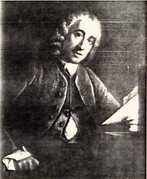 Figure 1
Governor Francis Fauquier, Founder of the Public Hospital. (CWF #67-2033)
Fauquier knew of general voluntary hospitals in England and he most probably knew Bethlehem Hospital for the insane in London (Fig. 2). Hospitals of any type in America were virtually nonexistent in 1766; there was only one, the Pennsylvania Hospital in Philadelphia (Fig. 3). Specialized hospitals did exist in England, Scotland and on the continent, but they were rare even there. Public provision for the insane in colonial American consisted of jails and, in some cases, almshouses for the indigent. However, with the exception of care provided at the Pennsylvania Hospital, no institutional system of treatment existed. If treatment was in evidence at all, it was a private matter for those families who had the means and the desire. Regardless of the reason, the eventual result of Fauquier's effort was not new legislation to ban the homeless insane from public areas, or construct additional jail cells. It was a hospital designed for the confinement, care and treatment of the mentally ill.
When additional encouragement for legislation was needed the following spring, Fauquier considered the hospital of "some importance to the ease and comfort of the whole community, as well as a point of charity."2 Fauquier died before making his proposal for a third time and the issue passed to his successor, Lord Botetourt. Perhaps inspired by a Virginia Gazette editorial of July 6, 1769, which referred to a murder by a lunatic that might have been prevented if a proper place of confinement existed, the House of Burgesses moved closer to enactment on
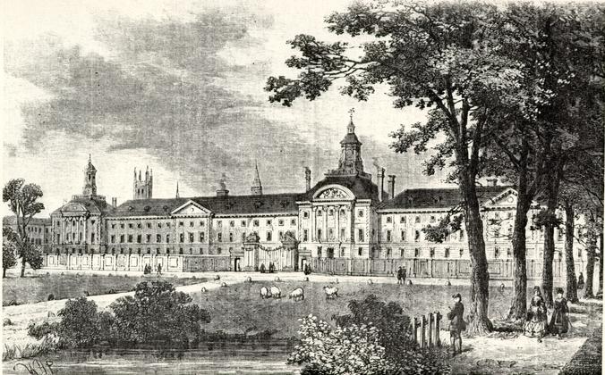 Figure 2
Bethlehem Hospital, Moorfields, London about 1750. (CWF #84-2764)
 Figure 3
Pennsylvania Hospital, Philadelphia, founded in 1755. This illustration was a subscription print. The right wing was constructed in 1756; the left wing dates to 1796; and the central pavilion dates to 1804. (Historical Society of Pennsylvania)
7
November 15, 1769, when it ordered draft legislation for the hospital. Just prior to this, Botetourt had asked William Byrd III to request the general hospital in Philadelphia to receive four lunatics then confined in the Public Gaol in Williamsburg. The Pennsylvania Hospital, which had set aside its cellar cells for the insane, replied favorably to the request. Upon hearing this, the House of Burgesses passed a resolution thanking Botetourt "for his kind and humane Attention to the Piteous Situation of the four unhappy People, who are disordered in their Senses . . . .3 Both the editorial and the request by Botetourt indicate an awareness and a realization that the issue of mental illness was, to some degree, a social and a public matter rather than a private one. It was not until June 4, 1770, that the burgesses passed a bill to establish the Public Hospital. In enacting the bill, the significant passage in the preamble, in addition to the need for restraint of those "who may be dangerous to society," is the statement that "no provision . . . [has] been yet made . . . towards effecting a cure of those whose cases are not become quite desperate."4 When the hospital opened in the fall of 1773 and began its uncharted course, its trustees emphasized cure, rather than mere confinement. Although security played its part, the desire for cure remains one key to this building's enigmatic beginning and to its medical and social significance thereafter.
ENGLISH VIRTUES
Of all the populated centers in colonial America, Williamsburg seems an unlikely choice for the establishment of an institution like the Public Hospital. After all, Williamsburg was not a bustling urban center with a disproportionately large number of the mentally ill. Virginia as a whole, in fact, had a large, yet dispersed population exceeding that of Pennsylvania, Maryland and Massachusetts. Except for the brief legislative seasons, Williamsburg remained a comparatively small community inhabited in 1770 by about 1500 people. The impetus for establishment, then, seems all important, since the actual need for a hospital in terms of patients did not appear great. In the first few years after its completion, the Public Hospital could not even fill up its first floor of twelve cells. In contrast, the Pennsylvania Hospital reported a rather large number of mentally ill patients in 1770, accounting for about one-third of the total patient population of 135.5 The reasons seem to lie more with the perceived rather than with the actual need. Even though proposed by a royal governor, the Public Hospital was accepted, managed and molded by citizens, albeit gentry, who fashioned themselves after English counterparts. If it is true that Virginia was a colony of "transplanters," a gentry-controlled society wishing to establish English institutions and to "fulfill English virtues," the Public Hospital could have been part of that desire.6 Despite the conceptual or physical 9 prototypes, however, the result was American, as were many other transplanted works. The imposition of a civilizing order on the American wilderness is a common theme in early American history, It is natural for man to create order out of disorder. The College of William and Mary, established in 1693, can be considered an example of intellectual order in a partially tamed wilderness. Similarly, the Public Hospital was a new type of institution for both a disorder in society and those "disordered in their senses." Establishing a "first" institution of any kind amounts to what Anthony King has characterized as a "formal acknowledgment of a change in society's arrangement for meeting a particular social need."7 The Public Hospital represented a change in the "moral boundaries" of the Williamsburg and Virginia communities. It was an age-old cultural problem recognized in a "formal" manner by associating it with a building type which connoted both societal control and medical cure.
Once established in legislation, the reality of a hospital fell out of the governor's hands and into those of the local citizens. From June 1770 until well into the next century, the hospital was run solely by a Court of Directors made up of selected trustees, the first of whom had been named in the establishing act: John Blair, William Nelson, Robert Carter, Peyton Randolph, Robert Carter Nicholas, John Randolph, Benjamin Waller, John Blair, Jr., George Wythe, Dudley Digges, Jr., Lewis Burwell, Thomas Nelson, Jr., Thomas Everard and John Tazewell. These were the men who held political authority and wielded 10 political power (Fig. 4). Members of this group occupied seven out of ten positions on Governor Lord Botetourt's executive officer staff. Among the hospitals' trustees were all three of the colony's legislative officials and four as councillors in the upper house of assembly. These men would have had the confidence of the Governor and would have been early advocates of the need for a hospital, if for no other reason than their enlightened "liberal" sense of social and community responsibility.8
The governor empowered this core group of trustees to choose an unpaid Court of Directors, consisting of a president and six other members, who would administer the fledgling operation of this new institution. To these laymen fell the task of selecting and purchasing a site; directing the construction of a building; selecting a hospital staff; setting regulations for its operation; overseeing many administrative and financial details; and most significantly, meeting frequently to examine and decide who would be admitted or discharged as patients. Beginning on Tuesday, October 12, 1773, the court set every following Tuesday as a time to meet and to receive prospective patients sent by the county magistrates. Sheriffs accompanied the patients and were paid five pounds of tobacco per mile for the trip. If they were necessary, other guards received three pounds of tobacco per mile.
 Figure 4
Royal Government in Virginia in 1770. Public Hospital Trustees denoted by ? and Public Hospital Building Committee denoted by +. (Chart by John Hemphill)
EARLY TREATMENT
Both the Act of Assembly and the announcement in 1773 that the Public Hospital was accepting patients mentioned the term "proper objects." "Proper objects" were neither the untreatable mentally retarded, nor the social problems of a community such as paupers, the homeless or alcoholics. But just what was the treatment for those "proper objects" and how did it affect cure?
Although the Public Hospital was actually run by lay keepers until the 1840s, local physicians attended the directors' meetings and treated the patients when necessary. Doctor John De Siqueyra was the first physician on call. Dr. Philip Barraud and Dr. John Minson Galt first assisted De Siqueyra and then succeeded him. Basically, treatment of the mentally ill was little different from the general practice of medicine in eighteenth-century America. There were special forms of treatment used at the hospital, involving both water and electricity, but, for the most part, traditionally-trained physicians practiced the so-called "heroic" treatment according to traditionally held medical theories regarding body humors:
…the functioning of the body and its temperament were governed by four humors, each corresponding to one of the elements that composed the cosmos. There was blood, corresponding to air and tending toward heat and moisture; phlem, corresponding to water and tending toward wet and cold; yellow or green bile (choler), corresponding to fire and tending toward heat and dryness; and black bile (whence the word "melancholy"), corresponding to earth and tending toward cold and 12 dryness. The health of the body depended upon the maintenance of balance in these humors.9There were no specialists for mental illness. That field would not come into being until the mid-nineteenth century. Even the "father of American psychiatry," Dr. Benjamin Rush of Philadelphia who foreshadowed the nineteenth-century Moral Management revolution in the treatment of mental illness, maintained his belief in humors with reference to the treatment of the insane. Despite the reliance on medical tradition, American physicians of the eighteenth century, especially those in Virginia, have been characterized as more successful "healers" than their European colleagues. This theory is based on the close association of medical theory and practice in America, a reliance on the apprentice system, and the practical necessity of less extreme forms of treatment.10 As Normain Dain notes in his history, Disordered Minds, patients at the Public Hospital were treated well, if only by virtue of a kind keeper and staff, a small town atmosphere and an attentive group of trustees. By circumstance, then, early care and treatment at the Public Hospital was as good as that available in comparable facilities in Philadelphia and probably better than in many of those described by John Howard in Europe.11
For a much more complete discussion of the administrative and medical history of the hospital the reader is directed to Shomer Zwelling's Quest for a Cure.
CHAPTER I
NOTES
CHAPTER II
PHILADELPHIA AND WILLIAMSBURG:
DESIGN, CONSTRUCTION AND USE
The Public Hospital's architectural history, like the history of its inception, is a combination of rich, well documented facts and plausible assumptions. There is no doubt that the most talented third generation builder-architect of Philadelphia, Robert Smith, designed the Public Hospital. The connection of Smith with Williamsburg is the undocumented and tantalizing part of the story, but it can be well imagined. William Byrd III of Westover is the person easily chosen as the Williamsburg-Smith connection (Fig. 5). Byrd knew Philadelphia through both personal experience and family connections and most likely knew Robert Smith and his work.
PHILADELPHIA CONNECTIONS
It was probably at the request of newly arrived Governor Botetourt that William Byrd corresponded with Mayor Thomas Willing of Philadelphia in 1769 regarding four lunatics in the Williamsburg Public Gaol.1 Willing's letter to Byrd in November 1769 stated that the four lunatics could be accommodated at the Pennsylvania Hospital. After the House of Burgesses secured the Governor's authorization, the "four unhappy people" were taken to Philadelphia the following March.
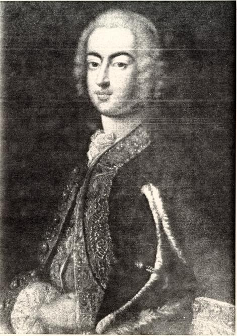 Figure 5
William Byrd III of Westover by Cosmo Alexandre (Virginia State Library) (CWF #56-CL-403)
Byrd was the logical person to correspond with Willing, having married Willing's sister, Mary, in 1761 (Fig. 6).2 If Robert Smith was not known to Byrd personally, Thomas Willing was, at least, well acquainted with Smith's work. Willing was a trustee of the Old Academy and New College of Pennsylvania, part of which was remodeled by Smith in 1750; he was-a subscriber to Christ Church, whose steeple Smith designed and constructed in 1751-1754; he was also a subscriber to the Presbyterian Church in Carlisle, Pennsylvania, which Smith designed in 1757; and he was a subscriber to the Pennsylvania Hospital, for which Smith was a subscriber and a design consultant.
Still another family connection could have put Byrd in touch with Smith. Dr. William Shippen, a well-known Germantown physician, was the maternal uncle of Mary Willing Byrd. Shippen is directly associated with Smith through the design for Nassau Hall at the College of New Jersey (now Princeton University), where the trustees approved in 1754 "the Plan drawn by Doct. W. Shippen and Mr. Robt. Smith." Edward Shippen, William's brother and a trustee of the College, mentioned the plan in a letter to his son, who was in school there.3
The other very likely link in this puzzle is Samuel Powel, a wealthy, well educated young man, who was the mayor of Philadelphia at the time of the Revolutionary War. In 1769 Powel, having returned from European travels, married, bought a house and began extensive remodeling work. Powel married Elizabeth Willing, Mary Willing Byrd's sister. Powel's house
 Figure 6
Mary Willing Byrd (1740-1814), second wife of William Byrd III. Attributed to Matthew Pratt. (Virginia State Library) (CWF #81-FD-1207)
16
stood on Third Street in Society Hill across the street from Thomas Willing and next to the house William and Mary Byrd had built and lived in from 1761-1764.4 Perhaps most interestingly, Powel employed Robert Smith from 1769-1773 to remodel and finish the interior of his house, during which time Smith provided plans for the Public Hospital.
Robert Smith and William Byrd no doubt had other mutual friends besides the Willing family, but suffice it to say, Smith's reputation would have been assurance that had Byrd inquired after a capable architect, Smith's name would have been mentioned. The fact that Robert Smith's drawings, or at least his "Description" of the hospital, were dated two months prior to the actual act establishing the institution and the appointment of a committee to determine a design, clearly indicates that he had been asked personally to submit a scheme. In all likelihood, Smith was chosen as the designer long before the public call for proposals.
ROBERT SMITH OF PHILADELPHIA
Robert Smith was born into a Scottish family of masons and builders in Dalkeith, near Edinburgh in 1722.5 The name Smith was well associated in the Edinburgh area with the building trade, the most prominent representative being James Smith (16461731).6 James Smith had replaced William Bruce as the leading architect in Scotland and held the position of overseer of Royal Works for thirty-five years. By the time Robert Smith had reached apprentice age, William Adam (1689-1748) had overtaken James Smith as the most prominent Scottish architect. Adam had served his apprenticeship under William Bruce and was the father of four sons, including architects John, Robert and James Adam.7 It is unknown whether Robert Smith actually worked for William Adam or perhaps John Adam, who had taken a greater role in the family business by the 1740s. The opportunity would have been possible, for Adam's business was booming in the 1730s - 40s. Of the many Adam works in the Edinburgh area, two coincide with Robert Smith's apprentice years: Dalkeith House, in his hometown, which Adam was remodeling in 1741-42; and the Edinburgh Royal Infirmary, which, although begun in 1738, was not completed until 1748 (Fig. 7). Smith probably emigrated no later than the end of 1748, since his first known American works were the Second Presbyterian Church in Philadelphia in February 1749 and the remodeling of Bush Hill, Governor Hamilton's house, in the same year. Historians have speculated that Smith's emigration is somehow connected to either the death of William
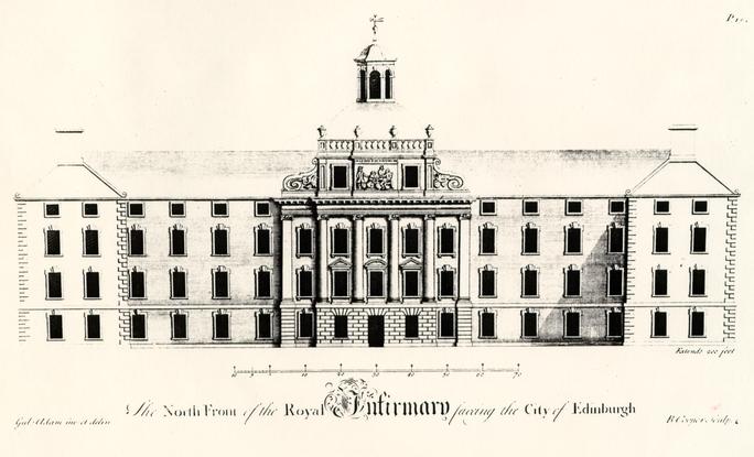 Figure 7
royal Infirmary, Edinburgh by William Adam, 1738-1748. From Adam's Vitruvius Scoticus. (CWF #84-2129)
18
Adam in June 1748 or to Pennsylvania Governor James Hamilton, who had been in London in 1748 to receive the governorship and may have visited family in Scotland.8 In any case, Robert Smith arrived in America well versed in his carpenter trade. Through his earliest known commissions, which included the building and possible design of Philadelphia's Christ Church steeple in 1751, his patrons quickly regarded him as a leading carpenter-architect in that city (Fig. 8).
The last fifty years of Philadelphia's colonial period (1725-1775) have been referred to as a "Golden Age."9 This was the period in which the city witnessed many of its noted cultural achievements, most of which were represented by masterful architectural designs. The second half of this era also encompasses Robert Smith's professional career. Smith certainly did not find Philadelphia an architectural vacuum. Gentlemen-architects and carpenter-builders had designed structures which rivaled England's most fashionable buildings.
Smith's known works can be considered among the best and most competent of those produced by second generation of Philadelphia "architects." They are not, however, extraordinary or innovative; it would be the next, the post-war, generation of builder-architects that would imaginatively expand upon traditional forms. Smith's generation, however, was responsible for the often overlooked role of translating architecture from British colonial to American. Although analysis is based on only a partially known oeuvre, with many buildings destroyed, altered
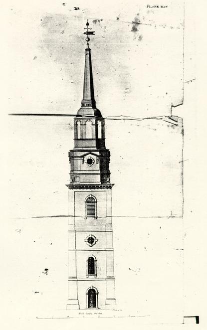 Figure 8
Christ Church Steeple, Philadelphia, 1752. From Owen Biddle, The Young Carpenter's Assistant, 1810. (CWF #84-2131)
19
or poorly illustrated, there is a discernible design pattern to Smith's work. His buildings may be grouped into three broad categories: domestic, ecclesiastical and institutional. A lack of extant examples and information prevents the inclusion of Smith's domestic buildings in the following sections.
During the decade of 1757-1767, Robert Smith built five churches: the First Presbyterian Church, Carlisle, Pa., 1757; St. Peter's Church, Philadelphia, 1759 (Fig. 9); St. Paul's Church, Philadelphia, 1760 (Fig. 10); the Third Presbyterian Church, Philadelphia, 1766 (Fig. 11); and Zion Lutheran Church, Philadelphia, 1767.10 With a few exceptions, these churches are designed in a fairly consistent form: three-bay pedimented gable ends, usually serving as a facade; gable-end Palladian window; bull's eye window in the tympanum; modillion cornice; roundheaded sash windows; giant order pilasters (chimneys are aligned with these on the long sides); five-bay sides composed of three central window bays between end door bays; and central gable-end doorways, usually with pediments. Smith's first church, the Second Presbyterian, 1794, which is preserved only in poor illustrations, was different from the others by virtue of its tower and steeple; St. Peter's Church alone had a cupola which was later replaced by a tower and steeple.
Just as Smith's ecclesiastical work falls into a form pattern, so does his institutional work: Nassau Hall (the University of New Jersey, later renamed Princeton University), New Jersey, 1753 (Fig. 12); Carpenter's Hall, Philadelphia, 1768
Figure 9
St. Peter's Church, Philadelphia, Robert Smith, 1759. The cupola was later replaced by a steeple designed by William Strickland. (Historical Society of Pennsylvania)
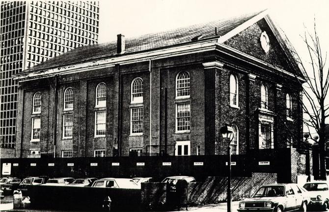 Figure 10
St. Paul's Church, Philadelphia, Robert Smith, 1760. Altered in the early nineteenth century. (CWF #84-TCM-502)
Figure 11
Third Presbyterian Church (Old Pine Street Church), Philadelphia, Robert Smith, 1766. Altered in the nineteenth century. (Historical Society of Pennsylvania)
Figure 12
Nassau Hall (the University of New Jersey, later renamed Princeton University). Robert Smith, 1753. Smith also designed the Dean's House seen on the right, ca. 1754. (Princeton University Library)
20
(Fig. 13); the Public Hospital, Williamsburg, 1770; and the Walnut Street Jail, Philadelphia, 1773 (Fig. 14). Because of its size and its function, Carpenters' Hall is not completely comparable, but were its wings extended, it would very much resemble the others. Typically, these large Georgian institutional buildings, a college, a hospital and a prison, were indistinguishable in exterior form. Each long side of the rectangular form (the Jail was U-shaped) was symmetrically divided by a projecting central pavilion composed of a central doorway flanked by windows. The hospital and jail had more typical three-bay pavilions, while Nassau Hall had a wider five-bay pavilion due to its excessive length. Centered in the pediment of each pavilion was a bull's eye window or in the case of the jail an elliptical window. Square-headed windows with arches, in contrast with the round-headed church windows, gave the facade a rather plain, flat appearance, which in the case of the college and jail was only enlivened by rusticated door surrounds. Also in contrast to Smith's church designs were the projecting lintels over the door arches. Georgian horizontality was maintained through a projecting watertable and a hip roof and on the hospital by a second story beltcourse. The jail, in a more fashionable design milieu, had corner pilasters without bases or capitals, which rose from the watertable. Finally, each building was graced with an octagonal cupola. In short, the large institutional building by Smith was a standard form, with certain details altered in each case. As exemplified by other
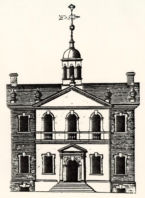 Figure 13
Carpenter's Hall, Philadelphia, Robert Smith, 1769. (CWF #86-372)
Figure 14
Walnut Street Jail, Philadelphia, Robert Smith, 1773. This is considered America's first penitentiary and was the structure which first drew Benjamin Henry Latrobe to Philadelphia when he was designing the Richmond Penitentiary.
21
college buildings, such as the rebuilt Wren Building at William and Mary, 1705 (Fig. 15); the second Harvard Hall, 1764; Hollis Hall at Harvard, 1762; University Hall at Brown, 1770; and Dartmouth Hall, 1784, the Georgian academic form did not deviate much after the early eighteenth century. Smith's hospital and jail (prison), both new building types in America, followed this academic form. Interestingly enough, the completed form of the Pennsylvania Hospital (1755) and the Almshouse (1766) (Fig. 16), both in Philadelphia and built by Samuel Rhoads and worked on by Robert Smith, seems to be based on British hospital examples, specifically the Orphan's Hospital, Walton's Hospital and the Royal Infirmary in Edinburgh and Bethlehem Hospital in London. The common form for these hospitals was that of an 11H11 or 11U11 in plan, with a central pavilion block which rose higher than the wings and was emphasized by a domed roof or steeple and transverse gable-end pavilions. American hospitals which appeared after Pennsylvania's, namely the New York Hospital, 1773-1776 (Fig. 17-18), and the Maryland Hospital for the Insane, 1797 (Fig. 19), follow the Pennsylvania example. Smith's design for the Public Hospital, on the other hand, did not conform in exterior appearance to the obvious prototypes, but, as suggested, was rather an undifferentiated Georgian form. It more closely resembled, both in scale and form, domestic designs in Scotland and England.11
Stylistically, the Public Hospital fits comfortably within the American Georgian design of the third-quarter of the
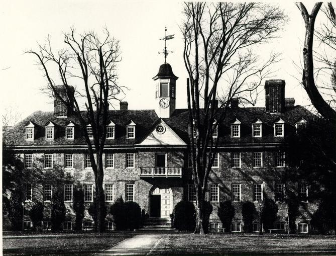 Figure 15
Wren Building, College of William and Mary, 1716. (CWF #K62-JC-446)
Figure 16
House of Employment/Almshouse (left) and the partially completed Pennsylvania Hospital (right) drawing by Nicholes Garrison. Engraved by James Hulett, 1767. (Historical Society of Pennsylvania)
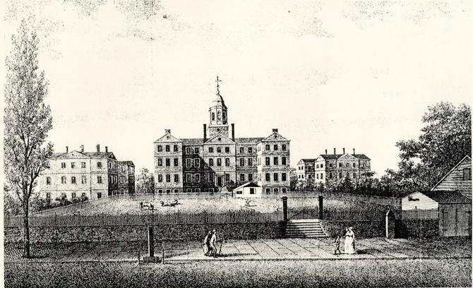 Figure 17
The New York Hospital as it appeared in the early nineteenth century. The building was completed just in time to be occupied as a Revolutionary War barracks. It opened as a hospital in 1791. The building on the left is the 1808 Asylum for the insane. (CWF #84-TS-1836)
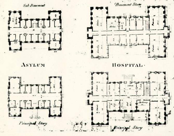 Figure 18
Plan of New York Hospital and Asylum. (CWF#84-TS-1837)
Figure 19
The Maryland Hospital for the Insane, Baltimore, 1797. Print by August Kollner, 1848. (Peale Museum)
22
eighteenth-century. It was, of course, characteristically provincial and outdated when compared to contemporary English works. Bootham Park Asylum in York (1772-77) (Fig. 20) and competitive designs for the new St. Luke's Hospital in London (1777), both for the insane, exhibit current neo-classical or neo-Palladian styles. In Williamsburg, the Public Hospital slipped into the colonial capital's architectural setting like an old friend. When compared to its two late colonial contemporaries, the Bruton Church tower (1769) and the Courthouse, (1770), the Public Hospital held an aesthetic edge only in its details, and even those had been simplified. Considering his ambitious architectural ideals, it is not surprising that Thomas Jefferson referred to English Georgian architecture as "the most wretched style I ever saw" and Virginia's version of it as "worse than any other part of America that I have seen."12 Jefferson obviously felt that an architectural opportunity had been lost with the Public Hospital, calling both it and the college "rude, misshapen piles, which, but that they have roofs, would be taken for brick-kilns."13
Smith's design for the Public Hospital was characteristic of his work only to a certain extent. Despite the fact that he had provided drawings and a written description, many details were locally derived. Eighteenth-century architectural drawings were generally very schematic; details such as moldings, hardware, brick bond, etc. were left to the supervising builder, and in the case of the hospital this was
 Figure 20
Bootham Park Asylum, York, England. 1772-1777. (CWF #85-EAC-1150-15)
23
Benjamin Powell. Robert Smith's "Description" closed with a statement which acknowledges the general nature of his drawings and description: "The above hints and a careful inspection of the plan may be sufficient to perform any part of the Building."14 Powell, perhaps at the direction of the Building Committee, relied on many Smith details but rejected others. One of the few sketched details copied into the directors' minutes provides an example. In his "Description," Smith states that the "plinth or Water table . . . may be of Moulding Bricks."15 The wall section sketch depicts a two-part molded watertable that was a common Philadelphia detail (Fig. 21). Photographic and archaeological evidence suggests that Powell ignored this recommendation and substituted a one-part bevelled watertable brick common to Williamsburg and Virginia. Similarly, Powell rejected Smith's recommendation to use stone for the foundation walls, probably as stone was not abundant in the Tidewater region. A survey of eighteenth-century Williamsburg and Virginia buildings, just as a survey focused on Philadelphia, Charleston, or any other region, indicates a common pool of architectural details used by local builders. Some of the hospital's design elements can be traced to Smith's design vocabulary seen in his previous work. Due to his absence in Williamsburg, however, the building also reflected local materials and building traditions.
Economic and social factors also played a part in the design process. The disputed price of imported materials indicates a measure of economy, which is not contradicted by
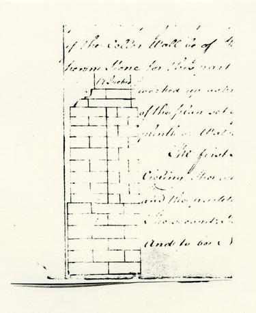 Figure 21
Sketch of Robert Smith's proposed watertable which was copied along with his "Description" into the Hospital Directors' Minutes Book. (CWF #81-1769)
24
architectural documentation. Although concerned to a certain degree about the building's appearance, some of the trustees conscientiously valued medical over architectural treatment, as the bequest of trustee William Nelson states:
I give and bequeath to the Court of directors appointed by Act of Assembly to erect and superintend the Public Hospital for the Reception of Lunaticks &c. the sum of one hundred pounds Current Money to be by them applyed towards the farther Relief of such poor Patients as may be sent to the said Hospital, as they in their Discretion may think fit, but not to the enlargement of the Building or to any other purpose.16For all intents and purposes, the Public Hospital had been organized and was administered like voluntary hospitals in England. If Nelson's bequest can be seen as a colonial extension of the English system, a loose parallel might be drawn to the idea suggested by Adrian Forty that ornament was "generally eschewed [at hospitals] . . . on the grounds that it was a misuse of charitable funds," giving eighteenth-century English voluntary hospitals an "austere and institutional appearance."17 During the construction of the Pennsylvania Hospital in 1755, Robert Smith and William Coleman were consulted about a "projection on the South side of the Ward and had given it as their Judgment that it would be no ornament and that several Physicians were of Opinion it could not be of any Advantage to the Patients, and it appearing to be likely to cost a considerable Sum, it is now agreed to drop the said proposed Projection."18 This reference suggests that Smith and Coleman considered the projection to be unornamental and therefore expendable, which seems to contradict the "austere" thesis, at least in this one instance.
CHAPTER II
NOTES
CHAPTER III
THE BUILDING COMMITTEE AND CONSTRUCTION
After the passage of the hospital act in June 1770, the trustees quickly moved to ensure its implementation. An unrecorded number of them met officially for the first court of directors' meeting at the Capitol on July 10, 1770. At this meeting five members were appointed as a building committee to "agree on a Plan for the hospital, and to advertise the building thereof; as also to receive Proposals for that Purpose of the several Undertakers, and to make a report of their Proceedings to the next Court."1 In less than a month the committee, composed of Peyton Randolph, John Randolph, Robert Carter Nicholas, John Blair, Jr., and Thomas Everard, had made a decision, which was announced in the Virginia Gazette on August 2:
The Committee appointed have, in Pursuance of the above order, agreed on a Plan for the HOSPITAL, and are ready to treat with all Undertakers, who may incline to engage in the Work. It is to be a large commodious Brick Building, and to be erected in or as near the City of Williamsburg as conveniently may be.2The plan agreed upon was that by Robert Smith. Curiously, Smith's description, which survived by virtue of its being copied into the first court of directors' minutes, is dated April 9, 1770, a full three months before the public call for a plan.
A Description of the Plan and Elevation of a Hospital for Virginia
The Plan consists of a Hall for a Staircase, behind There is the Keepers apartment, and 12 other Rooms chiefly for the Reception of mad People. The Stairs begin near the front Door and land on /blank/ 28 passage in the second Story. The second Story has 12 Rooms the same Dimensions as those in the first Story, and a Room over the Keepers Apartment which may serve the Managers of the Hospital to meet or may be divided which will make two other Rooms for Patients. The Hall is designed to be open as far as the landing of the Stairs the whole hight of both Storys. The cellers, shoud be about eight feet high between the under side of the joices and the Surface of the Celler floor. And the foundation must go 12 Inches lower which will make the whole hight of the Celler Wall on which you lay the first floor 9 feet. This Wall should be 19 Inches thick either of Stone or very hard Brick and the Partition Walls shoud be 14 inches thick. The first floor is designed 3 feet above the Surface of the Ground which will require the Wall about 2 feet or a little more raised above the said Surface. This part from the ground up to the top of the first floor should be cased-with hard Brick if the Celler Wall be of Stone, unless you go to the Expence of hewn Stone for this part which will be better. After the wall is worked up as high as the first floor to the full Demensions of the plan set off about 4 Inches for the finishing of the plinth or Water table which may be of Moulding Bricks. /Sketch included here/
The first Story is ten feet high from floor to Ceiling. The outside Walls all round 14 Inches thick and the partitions nine Inches thick of Bricks. The second Story is designed the same thickness and to be Nine feet six Inches high. The Windows are 6 hights of Glass 10 by 8 Inches for the hight and 4 for the Width. There must be a grate of Iron to the inside of each Window which may be fixed in the following Manner. Suppose this to be the Jaums of a Window and Irons fixed ready to receive the grates when the Building is finished. /Sketch here/ I would have 2 eyes of Iron made like the rough Scratch above, which should be made of Common flat bar Iron with a hole of an Inch diameter to receive a hook which will be fixed to the Grate, the other End split and turned up or down one Inch and built in the Brick work. These two eyes should be fixed about eight Inches above the bottom of the Window and two more fixed about the same distance from the top of the window, the Grate having four hooks to fit into those eyes May be set in and a hasp fixed to the Grate at top that will fall on a Staple drive into the lintel over the Window head fix on a padlock the whole will be safe. See this rough Scratch. /Sketch here/ 29
Dimensions of the Plan feet The Keepers Apartment 22 feet In: 6 Rooms on one side 11.0 70.6 2 End Walls 14 2.4 6 Ditto 9 4.6 2 Water Tables 4 .8 Whole length of Building 100. feet in: 2 Rooms 10.9 each 21.6 1 Passage 6.2 6.2 2 Walls 14 thick 2.4 2 Ditto 9 do. 1.6 2 Water Tables 4 do .8 Whole Width of Building 32.2 N. B. The middle part projects 3 feet 6 38.2 If there shoud be occasion for Fire to warm the common Rooms, there may be Stoves fixed in the Partition between two Rooms with the Mouth open to the Passage, by which means they make fires and the mad People cannot come at them. They should be fixed about two foot above the floor for fear of the Patients falling against the Stoves. See to the left hand on the Plan the place of two Stoves.
This Building will require about Two hundred thousand Bricks each Brick about 8 ¾ Long 2 3/8 Thick and 4 ½ Broad about 13 of such Bricks with Mortar will make one foot Superficial of a Nine Inch Wall or 19 ? of such to a fourteen Inch Wall. The Bricklayers must order it so that the Chimneys come out in the Roof at Equal distance from the middle otherwise they will have a very ill Effect. This may be easily done.
About 40 Thousand feet of Scantling will be wanted Superficial, which we reckon at one Inch 12 such feet makes one foot Cubical Measure.
16 Thousand feet of plank for Doors and floors about 1 1/2 Inch thick 2 Thousand feet of plank very good for Sashes &c.
5 Thousand of Inch Boards for Cornice to the Eves and other finishing besides Boarding the Roof.
The above hints and a careful inspection of the 30 plan may be sufficient to perform any part of the Building.
Philadelphia April 9, 1770
Robt. Smith
3
It would be interesting to know what information or instructions Smith's Williamsburg connection gave him. Had a prototype been suggested or was Smith expected to provide an appropriate design? The fact that the description was copied into the minutes without qualification indicates that the committee accepted the design without change. No evidence has ever placed Smith in Williamsburg, which might explain his recommendation of stone foundation walls. Unfamiliar with the region and its building practices, Smith did not know that Tidewater Virginia is virtually without native building stone. Not surprisingly, then, portions of Smith's specifications were simplified and adapted to local custom.
In September 1770, the building committee publicly announced that it would select a contractor on the 15th of the next month. In the intervening time, the committee left the "Plan and Terms" for the building with Jacob Bruce, clerk to the court, for the "Inspection of the Workmen."4 No record of the October meeting survives, but, according to the building contract which was not signed until January 1771, local builder Benjamin Powell had successfully bid the job.
Finding a builder had not occupied all of the committee's time, however, Efforts had been underway during the fall to select a suitable site for the building. The legislative act had called for a site not larger than four acres and "the 31 most healthy in situation that can be procured, and as convenient as may be to the city of Williamsburg."5 The directors reached an agreement in November and paid Thomas Walker £112 on December 1 for eight lots in the block bounded by Francis, Henry, Ireland and Nassau Streets (Fig. 22). A deed for the same was recorded nine days later.
Before about 1760, these lots were not available for development. Their selection as building sites was only possible after the seventeenth-century house on the block burned. The house, believed to have been built by Thomas Jones, was one of the few surviving seventeenth-century dwellings in Williamsburg. It may have been the house occupied by Governor Francis Nicholson after the State House in Jamestown burned in 1698 and the capital moved to Williamsburg.6
The chosen site in the southwest section of town was essentially on the boundary of the dense half-acre lots in the center of town and the open tracts that spread out from it. (Fig. 23). The four-acre tract bought for the hospital was in fact part of a pattern of larger open town lots that developed on the south side of Francis Street, contrasting with the smaller, more typical lots on the north side of the street.7 The William Byrd III property to the west contained a house placed near the street with outbuildings and gardens fenced within its ample four-acre expanse. Similarly, to the east was the four-acre Custis tract, which contained an enclosed group of outbuildings, gardens, and pasturage.8 In conformance with the adjacent tracts, the
 Figure 22
Detail from the Frenchman's Map, 1782, indicating a perimeter fence around the entire grounds. (CWF #N3434)
 Figure 23
Public Hospital site and environs in 1773. (CWF #84-TS-2114)
32
directors ordered the entire hospital grounds to be enclosed by a fence almost a year before completion of the building in 1773.9 This enclosure can be seen especially well on the town maps drawn during the Revolutionary War era (Figs. 24-25). The major departure from the treatment of neighboring sites was the hospital's placement on the rear of the lot, rather than near the street. This siting, for which no documented reasons exist, later became a major determining factor in the pattern of the hospital's nineteenth-century growth.
Benjamin Powell was a logical choice as the undertaker for the hospital construction. The Public Hospital, along with a number of projects, broke the hiatus in public building which had existed in Williamsburg since the completion of the Palace addition and Public Records Office of the early 1750s. Powell seemingly took the lion's share, if not all, of the new work in the 1760s and 1770s, due either to his experience and ability or, perhaps, to his social standing. He built the addition to the Public Gaol, the tower and steeple of Bruton Church in 1769, and made various repairs at the Capitol and private houses.
As a prominent man in town, Powell held a number of public offices. He owned a number of houses and lots, including his own house near the Capitol and an 1012 acre plantation in nearby York County. Although Powell is most remembered as an undertaker or contractor, he is variously described as a wheelwright, carpenter, and blacksmith. He directed a very successful business, engaging many laborers, craftsmen, and
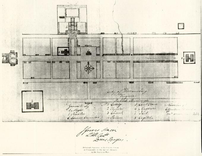 Figure 24
Simcoe Map, ca. 1781, indicating a perimeter fence around the Public Hospital (number 2) with a gate on axis with the front door. (CWF #68-2329)
 Figure 25
Detail of map, 1781 showing the Public Hospital (number 7) with its perimeter fence. (CWF #69-1512)
33
slaves, including his own. He is also known to have trained young and orphaned apprentices in the "art and mystery of a Carpenter or Joiner."10
The hospital directors later stated that "several Months elapsed before they could engage with a proper Person agreeable to their Wishes … ."11 Did Powell not bid on the job in October, 1770? If he didn't, why? Possibly Powell was engaged in other work and declined to get involved until January, conceivably upon the urging of several hospital directors. If this hypothetical explanation is the case, Powell might have been involved with the Courthouse on Market Square. All accounts pertaining to the construction of the Courthouse have been lost or destroyed, leaving part of its history to speculation. In any event, the following contract was made with Powell to complete the hospital within two years for £1,070:
Articles of Agreement indented made and concluded this the eighteenth day of January in the year of our Lord one thousand seven hundred and seventy one Between Benjamin Powell of the City of Williamsburg carpenter of the one part and the Court of Directors of the Hospital for the Reception of Ideots Lunatics and persons of insane and disordered Minds of the other part Witnesseth that the said Benjamin Powell for and in consideration of the sum of Money herein after mentioned doth covenant and agree with the said Court of directors that he will erect a large brick Building for an Hospital for the Reception of Ideots Lunatics and persons of Insane and disordered. Minds on the Lots lately purchased by the said Court of Directors of Thomas Walker agreable to the plan and explanation thereof hereto annexed The whole Wall of hard well burnt Bricks and laid with good Mortar the North front of the middle Building to have a neat Pediment of the South East and West ends to be hipped to have a neat Mundelian Cornice round the whole the Roof to be covered with plank and good Cypress Shingles the Frame and Scantling to be of good Oak or poplar and of proper 34 Sizes for such a Building the Floors to be laid with good Plank well seasoned one and a half inch thick and free from Sap the outward Doors and those to the Middle Rooms to be paneled and the others strong batten Doors and the said Benjamin Powell doth agree to furnish all the materials for the said Building except the Grates and such other things as are usually imported from England and that he will finish and compleat the whole in a neat strong and workman like manner agreable to the plan and explanation thereof aforesaid within two years from the date hereof In Consideration whereof the said Court of Directors do agree to pay the said Benjamin Powell one thousand and seventhy pounds in the following manner that is to say two hundred and fifty pounds part thereof in hand and the Residue at such Times and in such proportions as the said Court of Directors shall think fit to direct having regard to the progress of the work.12
Presumably, a number of sawyers began the task of felling oak, poplar, and pine trees in the winter of 1771. Through the spring and summer, hewn and cut logs were added to the increasing inventory of finished timbers which were numbered and set aside.13 At the same time, frames for windows and doors would have been started, with the actual sash and doors following. Meanwhile, to certain directors fell the responsibility of procuring materials "as are usually imported from England." Three days following Powell's commitment to the project William Nelson wrote to London merchant Robert Cary for an unspecified number of "Articles,"14 which amounted to the sizeable sum of £188.13..9.15 The only documented item from this order is the weather vane, recorded by virtue of a price dispute, as these letters from Nelson to Cary testify:
[Sept. 5, 1771]
35…the Invoice of the Cross, Vane & ca amounting to 27.14..-which is received & I credit you for it in Account; but the Builder says that it is most extravagantly dear, & that he hath had one made here nearly as Good for £12 our Currency, tho' the spindle is not turned, as this is; and therefore, if no Abatement is made, I shall think they take a very unfair Advantage of Charging what they please for their goods.
16
[Nov. 21, 1771]
I hope you will try to get some Allowance for the Excessive Charge of the Weather Cock, which I complain'd of before or I shall think I am hardly dealt by.17
[Feb. 21, 1772]
I observe the Reasons, which Mr. Millington gives for the high Price of the Vane & Ca. which I suppose I must be satisfied with tho not convinced that it was not too Dear.18
Director Robert Carter was responsible for ordering the window and transom grates specified in Smith's "Description." Carter's charge was not due to circumstance; he was a partner in the Baltimore Iron Works from which he ordered the grates in April 1771:
. . . I send 2 patterns of wood to shew the sizes of grates wanted for an hospital now building here for the reception of Lunaticks 24 of the larger size are wanted 24 of the other size are wanted, both sizes to be made of wrought iron and 48 hoocks--the directors who superintend the building expect that you signify to me the price you ask for the same, also the time you require to finish the said work-- . . . .19The grates, which Smith must have modelled on a Philadelphia example, were shipped from Baltimore on October 2, 1771.20
Having coordinated the acquisition of several crucial materials by the fall of 1771, Powell began putting them all 36 together (Fig. 26). Brick mason Samuel Spurr had been chosen by Powell earlier in the year. Spurr had previously worked for Powell at the jail and probably at the church as well.21 While the wood framing members were prepared and the grates were wrought, Spurr was undoubtedly making bricks and lime for the hospital, as indicated by his advertisement in the Virginia Gazette on October 2, 1771:
The frames for doors and windows, as well as the grates for the same, had to be on hand before Spurr began his work, even though the late starting date meant that not much would get done before cold weather halted the work.Williamsburg, October 2, 1771.
THE Subscriber will give good Wages, and Accomodations, to two or three Journeymen BRICKLAYERS, for the remaining Part of the Season, to work upon the Hospital building in this City. Plenty of Bricks and Lime is ready, so that they were will be no Delay.
SAMUEL SPURR22
On December 16, 1771, soon after Spurr started the foundations, the directors ordered that the walls be increased by one half brick from the width specified by Robert Smith. Either the builder or the mason had recommended thicker walls. Archaeology confirmed this increase of about 4" for the outer foundation walls and the central north-south pavilion walls.23 On the average, Spurr's bricks were found to be slightly larger than the specified size.24
By February 1772, the directors realized that there would be a building cost overrun. Just to finish the building
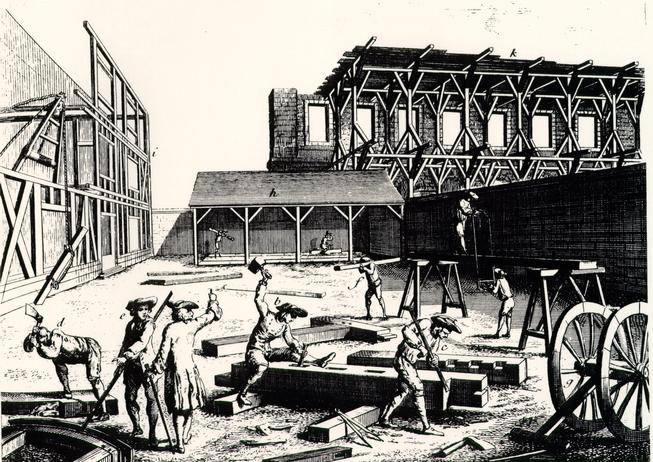 Figure 26
This illustration from Diderot depicts the type of activity associated with the Hospital's construction. (CWF #85-235)
37
they would have to spend thirty percent more than their appropriated E1200. In addition, they pointed out to the burgesses that other necessary expenses were apparent, including the enclosure of a "Garden and Yards for Patients to walk and take in Air in" and salaries for a keeper and matron.25 The burgesses responded with an additional allocation of £800 in April of that year, the same month in which the stone steps ordered by Director Robert Carter Nicholas arrived from England.
Work proceeded during the spring, summer, and fall of 1772, but the building was not yet finished by the scheduled completion date of January, 1773. Eight months later, however, the directors met, examined the building, found it finished "according to Agreement," and turned its operation over to James Galt, the first "Keeper of the Hospital."26 Two days later an advertisement appeared in the Virginia Gazette informing the public of the hospital's completion and opening date, October 12, 1773.27
CHAPTER III
NOTES
CHAPTER IV
PLAN, FUNCTION AND USE
The Public Hospital's exterior appearance was culturally determined its institutional and public nature. Its familiar style associated it with a certain class of society, whose values and ideas were implicit in establishment and purpose of the institution. Yet, as we have seen, the exterior form was undifferentiated as to function. Robert Smith designed a college and a prison which did not look all that different from the Public Hospital. If the architect used such an ideal exterior form, did he also design an ideal interior plan to facilitate the hospital's intended use and purpose? To answer this we must look to the founders or clients of the building, who established its social role and setting; to the traditional or existing architectural prototypes available, which may or may not have reflected a similar need in different regions or cultures; and to the users of the building, who eventually determine the success or failure of the interior spatial arrangement.
Even though it was established as a publicly funded institution and then continued under the jurisdiction of the state after the Revolution, the Public Hospital was, by and large, operated along the lines of the private voluntary hospital system in England. Medieval hospitals in Europe had developed principally by benefactors and monastic nursing orders who hoped for spiritual salvation through charitable acts.1 These open
42
plan hospitals were consequently arranged around religious services, specifically an altar. By the eighteenth century, the religious hospital had been replaced by a secular version established, funded and privately administered by mid-level gentry. According to Adrian Forty, cure for the indigent and "poor" represented only one part of these hospitals' function. Moral reform was the other goal. The private subscribers administered the hospital, appointed the doctors, and controlled admissions. Along with the prestige, these managers used the hospital as a device to reform and control the cost of the relief system for the poor. Concern for both the "deserving" and the "undeserving" poor led to the creation of an institutional setting as a means of moral reform. In America, the hospital system developed in a dual manner. Publicly controlled almshouse hospitals served the pauper, the criminal, the insane, the orphan, foundlings, and all those who could not afford a physician's house call.2 Voluntary hospitals of a better nature also developed, the Pennsylvania and New York hospitals being early and prime examples. These institutions were modelled on the subscriber-run voluntary hospitals in Britain, for example, the London Hospital of 1752 (Fig. 27). They differed from almshouse hospitals by having a more competent staff, selected patients, medical students, and a lay board of administrators. Physicians who served in voluntary hospitals did so primarily as a social and honorary obligation. The arrangement of space in
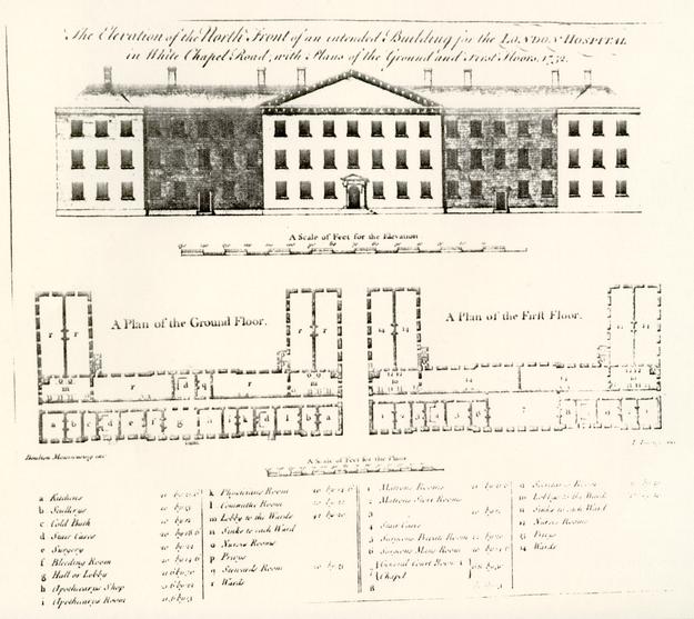 Figure 27
The London Hospital, 1752. (CWF #84-TS-1839)
43
such a hospital was consequently organized by authority and social function.
Robert Smith arranged the Public Hospital interior in response to the four groups of people who would interact within the building. This approach resulted in the placement of public and administrative spaces in the most prominent positions, very much like both English and Scottish examples and also Smith's other institutional works. Upon entering the Public Hospital through its north doors one encountered an entrance and stair hall that occupied the north half of the central pavilion (Figs. 28-29-30). An open staircase on the east wall of this hall led to the second floor and the most significant room in the building: the directors' meeting room. In this room the directors administered the hospital and interviewed patients for admission or discharge. There was no physician's room, indicating his relatively adjunct position at this time. Next in terms of importance were the keeper's quarters separated from the entrance hall by a lateral passage in the central pavilion. The keeper thus lived in the building and oversaw the daily supervision of the patients and staff. From his central location the keeper could easily reach the cells on either floor, the hail, the directors' room, the cellar, and the exterior through a south door. The staff, consisting of a matron and several attendants (both hired and slave), had use of the central pavilion cellar, which contained a kitchen, laundry, and storeroom, with access through an exterior bulkhead entrance on
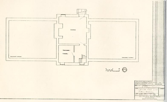 Figure 28
Public Hospital. Reconstructed cellar plan ca. 1773. (JFW, TCM)
 Figure 29
Public Hospital. Reconstructed first floor ca. 1773. (JFW, TCM)
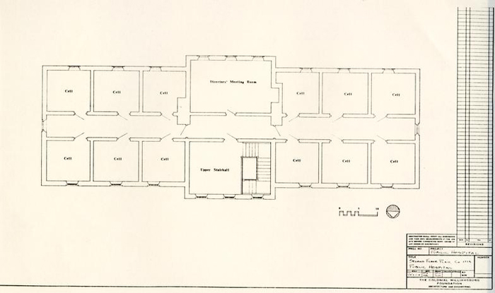 Figure 30
Public Hospital. Reconstructed second floor plan ca. 1773. (JFW, TCM)
44
the south or by interior stairs. The most inaccessible spaces, the cells of the patients, were reached through closed central passages in the wings of both floors. Patients took food in their cells and went out only for exercise in the flanking exercise yards reached by east and west end doors. Physically, and in principal, this arrangement is not very different from Robert Smith's plan for Nassau Hall, where the most socially important spaces were grouped in the central pavilion with lesser functions in the wings (Fig. 31). Smith's plan for the Walnut Street Jail also had a similarly organized plan of important administrative spaces in the most publicly accessible parts of the building, with the work and storage spaces and the prisoners' cells in privately controlled areas (Fig. 32). Thus, we find that a system of interior arrangement was at work, with certain basic principles applied in each case. Given this premise of a basic social governing system, Smith could very well have designed the Public Hospital's interior based on the requirements combined with the preferred overall form of the building. There is, however, good reason to think that Smith turned to a specific and appropriate prototype when designing the hospital's "ideal" interior.
On December 7, 1754, Samuel Rhoads presented the managers of the Pennsylvania Hospital with a plan and elevation for the new building. Two weeks later Rhoads appeared again and "laid before the Managers the plan of the several floors and Elevations of the Edinburgh Infirmary some parts of which they
Figure 31
Nassau Hall (College of New Jersey: Princeton). Plan by Paul Norton (?) (Princeton University Library)
Figure 32
Walnut Street Jail, Robert Smith 1773-1777. (Library Company of Philadelphia)
45
have taken into their further considerations" (Figs. 33).3 While this prototype was not copied in all respects for the first general hospital in America, the individual basement cells for the insane, arranged on either side of a central corridor, most certainly were taken from the Edinburgh example (Fig. 34).4 Robert Smith probably saw the Edinburgh Royal Infirmary firsthand, as discussed earlier, but more importantly, he knew of its adaptation for the Philadelphia building, which would have been a much more vivid prototype.5
What then were the determining factors which made this interior arrangement an ideal plan for the Public Hospital? The clues can be found in society's reasons for needing the institution. To reiterate, in their legislation the founders of the hospital expressed two concerns: fear and cure. Until the nineteenth century, medical treatment had little effect on the patients' physical environment. on the other hand, security played a great role in the purpose, function and design of the hospital. In fact, accommodations for the insane were more closely allied with those for the criminal than those for the sick. Before specialized settings were created, the insane were commonly placed in jails where the use of individual cells was typical, especially in large institutions. European and American examples were similar except perhaps for scale (Figs. 35 & 36). The intention was to remove a threat to society and, once inside an institution, to separate and secure the patients from each other and from their keepers. This was achieved primarily
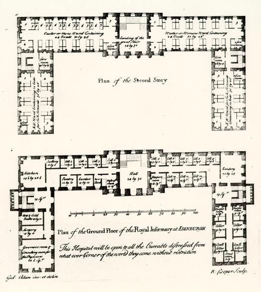 Figure 33
Edinburgh Infirmary, ground and fourth floor plans. (William Adam, Vitruvius Scoticus) (CWF #84-2130)
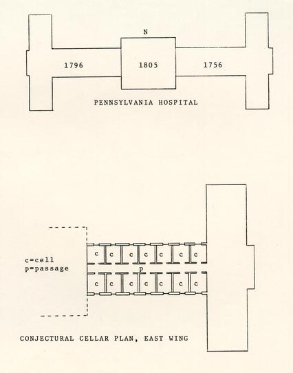 Figure 34
A conjectural east wing cellar plan showing the hyphen where the cells for the insane were located. (TCM)
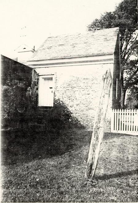 Figure 35
Northhampton County Jail, Eastville, Virginia, eighteenth century. (WF #83-1224)
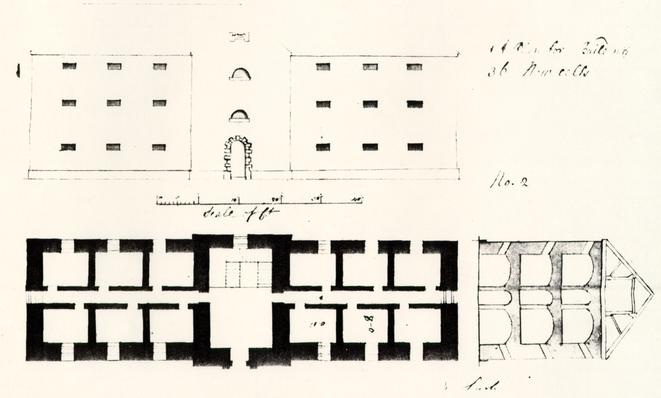 Figure 36
Fisherton Anger County Gaol, cell block, E. Lush, 1791. The type of English county jail that might have typically held the mentally ill. Note the remarkable similarity to the Public Hospital Plan. (CWF #84-TS-1835)
46
through physical restraints: individual cells, barred windows, barred transoms, locked and bolted doors, high fences and walls, and one or a combination of individual leg and wrist fetters, straight jackets, or special restraining beds and chairs. Again, even if Smith had known of Scottish settings for the insane, he would have been much more familiar with the Pennsylvania Hospital. "Mechanisms" of security were used routinely at the Pennsylvania Hospital, including fetters, straight jackets, heavily secured doors, high exercise yard fences, and barred windows; The latter were documented in the hospital minutes for 1758: "It appearing by the Reports that several of the Lunaticks have made their Escape owing to the iron bars of the Cells being too slender. Tis agreed that the Monthly Committee employ the same Smith [i.e. blacksmith] who made them to make them stronger & more secure."6 When it came to designing the Public Hospital, Robert Smith's explicit description and sketches of window and transom grates expressed at least one purpose and intention of its managers.
EARLY USE AND FUNCTION
The early use and function of the hospital can best be described as trial and adaptation. With a small patient population in its earliest years of operation, the keeper, physicians and directors slowly learned the business of a "Madhouse." Much of this business involved ordinary daily activities such as might be found on a plantation with a similar number of people to feed and clothe, gardens to tend, and structures to maintain. Outbuildings mentioned in 1744 were a well, a smokehouse, and a house for straw (necessary for patients' bedding). Other outbuildings were added to the complex at a steady rate. Garden implements seem to dominate the accounts of purchased goods, along with domestic items such as candles, soap, blankets, mops, brooms, buckets, tin and earthen cans and pans, wooden trays, chamberpots, etc. Provision of clothing (breeches, jackets, gowns and shoes) appears to have been adequate, and the extensive accounts of purchased food items indicate a surprisingly complete diet.7
In the earliest years, local builders, carpenters, and masons were called upon to replaster walls and fix broken windows (planked up or filled with "dead lights"); to repair the cellar kitchen floor, chimney or hearth and to build an oven; to whitewash the interior almost annually; and frequently to construct coffins. Other accounts reflect the specialized function of the building, which necessitated certain additions or alterations. Before the building was finished the directors 48 realized that enclosed "airing" yards would be required for the patients, so in their request for additional funds in 1772 they mentioned that "it will be necessary to inclose a Garden and Yards for Patients to talk and take the Air in."8 Although there is no mention of yards, fences or walls in either Smith's "Description" or in Powell's contract, an "airing" yard was an indispensable appendage of any facility of incarceration. European almshouses, prisons, and hospitals for the insane all had attached yards enclosed by high fences or walls. Typically, these were adjacent to the building, segregated, and usually barren of amenities (Fig. 37). The fence erected by Benjamin Powell in the fall of 1773 most likely served the dual purpose of enclosing the hospital lots and providing an area for air and exercise. Due to the small number of patients during the earliest years and the advent of the war, it was not until about 1790 that a sufficient number of patients justified the addition of 80' x 30' fenced exercise yards flanking the hospital at each end. These paled fences, which were replaced in 1799 by ten foot high brick walls, enclosed yards which until 1800 were devoid of structures or shelters, resembling the description of an English "airing" yard "where no tree nor shrub nor flower nor blade of grass grew...;"9 The two yards made possible the segregation of male and female inmates. In large hospitals for the insane, such as Bethlehem Hospital, and in prisons or almshouses, men and women were further classified by degree of illness into separate yards.10
Figure 37
the first Bethlehem Hospital, 1676, shown here, originally had one exercise yard at each end of the building enclosed by 14' brick walls. When the new Bethlehem Hospital was constructed in 1815 it featured numerous exercise yards for various classes of patients. (Bethlehem Hospital Archives) (CWF #86-365)
The hospital stayed in operation during the Revolutionary War, but only barely. Petitions to the governor and the House of Delegates throughout the war years consistently refer to a shortage of operating funds, supplies, and salaries for the keeper and physicians. These problems forced the hospital to close sometime around 1781, but by 1786 a new General Assembly act of incorporation had put it back in business.
Years of neglect necessitated extensive repairs after this hiatus. But, more importantly, a level of full operation in the late 1780s led to alterations that indicated the interaction of patients and staff in the building. One of the obvious oversights in Robert Smith's interior plan was the reliance on one stairway to the second floor. By its placement, this one staircase served all of the user groups: the directors, the staff, and the patients. For patients to be taken from the second floor out to the exercise yards, they had to walk through the entrance hall, the most public space. It was apparently decided that this created a circulation problem, and staircases were ordered built at each end of the passages in 1790, providing a more private means of circulation for both staff and patients.11
Other alterations at about this same time include the installation of a partition dividing the keeper's quarters into two rooms and the addition of isolation cells in the cellar for patients with the "raving phrensy."12 This last alteration foreshadowed the classification system that became a major aspect 50 of the Moral Management era in the nineteenth century. In effect, there was some acknowledgement at this time that separating patients by degree of disorder would be beneficial to the patients, especially those with less severe problems. The specific solution, however, cannot be seen as humanitarian.
The new state government's commitment to reopen and reestablish the Public Hospital in 1786 was a crucial one. Continuance of the institution after the war meant that it had become the first state-controlled hospital for the insane in America. Equally important, it had been given new life at a time when the town needed an economic anchor. Onley Winsor, who visited Williamsburg just after the repairs in 1786, left a graphic picture of the hospital's physical relationship to the town at that time.
Here is a large handsome brick Mad House (for Lunaticks &c)--all the public buildings except the Mad House, are in a decaying situation, as most of the Private buildings, business haveing almost entirely left this place since the removal of the Government.13
By June 1799 the directors announced to the public that the hospital was full and would not accept new patients. With the new century the hospital steadily expanded in both its number of patients and number of buildings. The hospital was also entering the age of the American psychiatric profession, an age during which hospital architecture and medical treatment became much more closely allied.
CHAPTER IV
NOTES
CHAPTER V
NINETEENTH-CENTURY GROWTH
If the eighteenth-century history of the Public Hospital is characterized by a somewhat isolated and idiosyncratic effort at treatment, its nineteenth-century history reflects the "age of the asylum" and the increasingly important role of the psychiatric profession in the appearance and function of hospitals. But, as Norman Dain has noted, the administration of Dr. Alexander D. Galt in the hospital's second major period, 1800-1841, did not take advantage of the new theories of Moral Management which had developed in England and France around the turn of the century.1 From Pinel and Tuke, in France and England respectively, came a revolutionary theory regarding the treatment of the insane that stressed non-restraint, kindness, and provision of un-jail-like environment for the patients (Figs. 38 & 39). The hospital in Williamsburg evolved in relative isolation from these new theories of mental health treatment until just before Dr. John M. Galt II became superintendent in 1841.
By 1804 outbuildings had accumulated to the south of the hospital, giving the site a full range of subsidiary domestic structures: well, smokehouse, house for straw, privies, stable, dairy, corn crib, sheds, and bath house.2 A small one-and-a-half story house, which came with the property just south of Ireland Street, eventually served as the matron's residence (Fig. 40).
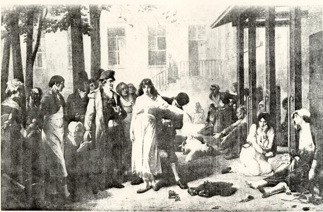 Figure 38
Dr. Philippe Pinel, one of the pioneers of moral management theories. (CWF #81-FD-4376)
 Figure 39
Samuel Tuke, founder of the Retreat in York and the father of Moral Management practices. (CWF #86-373)
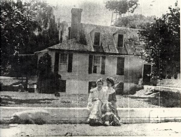 Figure 40
The Galt Cottage. (CWF #66-791)
By this time, a wooden fence enclosed the entire hospital site; gardens, with their own fences, occupied part of the enclosed grounds; ten-foot-high brick walls had replaced the exercise yard fences flanking the hospital; and the exercise yards contained "covered walks" for the patients. Because the hospital had continued to run at capacity since 1799, an additional building for "the accommodation of the patients, the keeper and matron" was constructed in 1804-1805 as a detached structure slightly south and east of the main building. The new building was later referred to as the convalescent or "bettering house." An 1821 insurance policy described this building as "brick with a wooden roof, two stories high, and 32' x 18'."3
Minutes of the Board of Directors are missing for the period 1801-1822, but repair accounts survive and indicate a wide range of maintenance work. Typifying this maintenance work are three accounts by a bricklayer, a carpenter, and a blacksmith. Bricklayer James Semple's 1805 account shows that he repaired ovens, chimney backs, doors, and windows; underpinned a smokehouse, stable and necessary; built a well; laid a brick cellar floor; did plaster work; and whitewashed 27 rooms. In 1811 carpenter John Bowden replaced or installed window glass, locks, doors and door sills, floors, steps, washboards, and cellar caps. He also made coffins. Blacksmith James Hay's account from 1815 documents a wide range of work: repairing keys, locks, carts, wheelbarrows, hasps, tools, and a ducking chair. There are also many references to Hay altering or 55 repairing leg irons and chains--typical eighteenth- and early-nineteenth century leg irons required a blacksmith to put them on and take them off (Fig. 41).4
The location of outbuildings to the south of the hospital on the four-acre site dictated the placement of any new buildings for patients to the north or front of the original building (Fig. 42). The first of these additions was a 40' x 33' two-story brick building containing twelve cells, constructed in 1820-22 just to the northeast of the original building. This $4,000 building, which was roughly equal in both size and accommodation to one wing of the original building, was duplicated with a corresponding building to the northwest in 1824-25. These flanking buildings can be seen in a drawing (believed to have been executed by keeper Dickie Galt in 1829) that shows the north elevation of the original building after the addition in 1828 of a "portico" or porch and the replacement of original window sash and sills (Fig. 43). The full range of cellar windows in the drawing is a mystery, since archaeologists determined that the cellar was originally confined to the pavilion. The dotted lines connecting the buildings represent the 10 foot-high brick walls enclosing the exercise yards. If the two buildings identified on the drawing as a kitchen and laundry are reversed, the kitchen plan corresponds to the detached kitchen documented by archaeology.5
Additional space was again needed in 1833, prompting an extension of the 1820 and 1824 buildings to the north. From
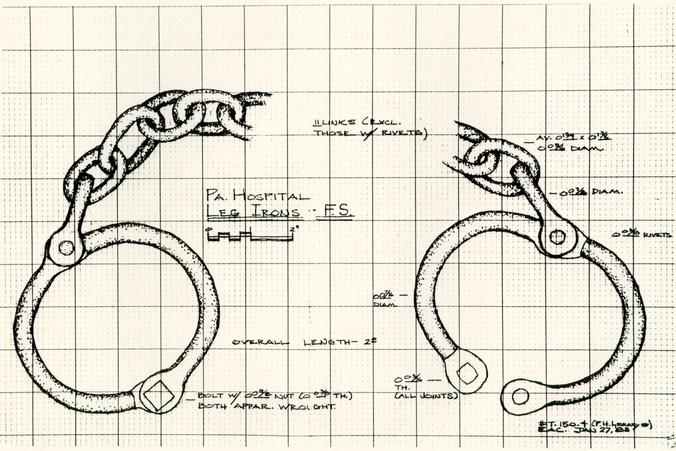 Figure 41
Leg irons from the Pennsylvania Hospital. (Edward A. Chappell) (CWF #86-368)
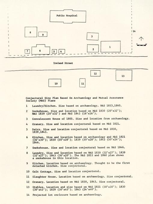 Figure 42
Conjectural site plan of Public Hospital showing outbuildings. (TCM)
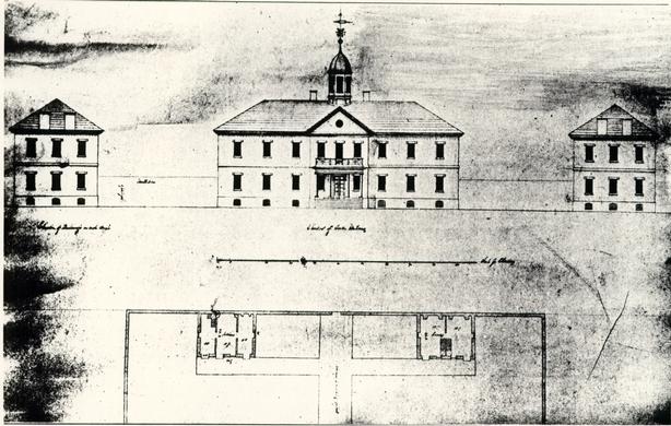 Figure 43
Drawing of the Public Hospital thought to be by Keeper Dickie Galt, 1829. The structures shown in plan are labelled kitchen and laundry. (CWF #81-2989)
56
builder Albert Chewning's contract, these 20-cell additions do not seem any more advanced in detail or in the use of interior space than the buildings to which they were being added or, for that matter, the original building. This effort to use the earlier buildings as a model, ignoring the new currents of Moral Management, seems to confirm the view that Dr. Alexander D. Galt's administration of the hospital did not reflect the emerging progressive concepts practiced by some of his contemporaries. By all accounts, his treatment of the mentally ill, and practice of medicine in general, was extremely conservative.6
CHAPTER V
NOTES
CHAPTER VI
NEW DIRECTIONS, 1838 - 1885
Beginning in the 1840s, the Public Hospital entered a modern era in which the superintendent was not only a physician but a physician trained in psychiatry. More importantly, physician-superintendents were cognizant of the tenets of Moral Management and eager to put into effect the architectural and administrative changes with which the new philosophy was associated.
A turning point came in 1838 when the directors ordered newly appointed keeper Philip Barziza "to make a Journey to the North for the purpose of inspecting the plans, of the principal hospitals in that quarter; taking plans of such parts as he may approve; and acquaint himself with all that may seem worthy of imitation, in the treatment of patients."1 With the director's support and a new "liberal spirit manifested by the general assembly," Barziza took the reins and began instituting changes which the directors hoped would "make the success of the institution commensurate with the reasonable expectations of the public."2 The timely appropriation for additional construction at this same time enabled the directors and Barziza to put into effect the first practice of Moral Management at the hospital. For example, certain specified details of a new building under construction were changed at the last minute to create a more 59 domestic, less jail-like environment for the patients. The hospital administrator implemented these changes in a third-floor addition to the original 1770 building and an adjoining three-story wing to the west where the exercise yard had been (Fig. 44). A matching east wing was then constructed in 1842-44. Coincidentally, Dr. Stribling, a young physician who in 1836 had taken control of Western State Hospital in Staunton, Virginia (founded in 1828), made a similar inspection tour of northern asylums and also implemented architectural manifestations of Moral Management.3 The second building at Western State, constructed by 1838, features cast iron sashes; a generally high level of finish in patients' rooms, including panelled doors and wire mesh transom screen; improved ventilation; and large common rooms and corridors for social interaction (Figs. 45-47).4 Stribling took strongly to Moral Management theories. His report to the State Assembly in 1838 probably helped inspire Eastern State Hospital directors to initiate changes.5
The American asylum grand tour was not new. In fact, it had become de rigueur for emerging young professionals trained in the new field of psychiatry and seeking the latest in a building type which was developing as rapidly as their own field. Barziza's and Stribling's tours for inspiration and innovation would have no doubt taken them to a number of the following institutions: the Friends' Asylum for the Insane in Pennsylvania (1817) (Fig. 48), New York's Bloomingdale Asylum (1821) (Fig. 49), the Hartford Retreat for the Insane (1824) in Connecticut
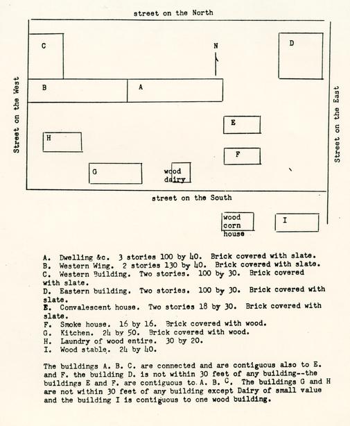 Figure 44
Public Hospital outbuildings shown on a 1843 Mutual Assurance Society policy (No. 11,265). Plan redrawn from original by Linda Rowe.
Figure 45
Western State Hospital; Staunton, Virginia. constructed 1828 and shown here in 1838. The principal building is shown in its original form before the addition of porticoes. From a sketch by R. C. Lang and a drawing by A. C. Smith (WSH Annual Report)
Figure 46
An exterior cast iron sash in front of its exterior wooden equivalent. Western State Hospital, 1840s.
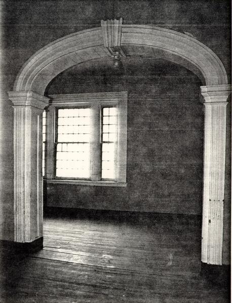 Figure 47
Dayroom area. Western State Hospital. (CWF #84-WJG-1949)
Figure 48
Friend's Asylum; Frankford, Pennsylvania; constructed 1817; shown here in 1835. (Historical Society of Pennsylvania)
Figure 49
Bloomingdale Asylum, New York, constructed 1821. (New York Public Library)
60
(Fig. 50), the McLean Asylum for the Insane (1818) near Boston (Fig. 51), the Worcester State Lunatic Hospital (1833) in Massachusetts (Fig. 52), and the Maryland Hospital for the Insane (1798, 1838) in Baltimore (Fig. 19). Architect Charles Bulfinch .made a tour in 1816 of hospitals in New York, Philadelphia, and Baltimore before converting the Barrell House near Boston into a hospital for the insane (later named the McLean Hospital) Fig. 53). The Pennsylvania and New York hospitals' plans are reflected in Bulfinch's double-loaded corridor of cells for the three-story wings he attached to the Barrell House. Two years later, the new superintendent/physician and an interested trustee of this new Boston asylum also made a tour of the New York and Philadelphia hospitals, this time including an inspection of the newly finished Friend's Asylum at Frankford, Pennsylvania. The Pennsylvania Hospital had in turn sent their physicians on a northern asylum inspection tour in 1848.6 It was not uncommon for architects to travel and examine new buildings, but the tours by physicians and administrators is indicative of the rate at which the two coinciding specialties were moving. Into this already changing milieu at the Eastern Lunatic Asylum, as the Public Hospital was then called, came a twenty-two-year-old doctor fresh out of medical school. The Galts had been keepers, matrons and physicians. Now their ranks would include a professional superintendent trained in psychiatry.
John Minson Galt II succeeded his father as physician at the hospital on June 1, 1841, three months after the General
Figure 50
The Hartford Retreat; Hartford, Connecticut; constructed 1824. (Connecticut Historical Society)
Figure 51
McLean Asylum, Boston, begun 1817, shown here in the 1840s. (Massachusetts Historical Society)
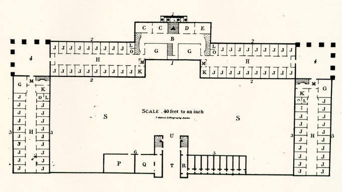 Figure 52
Plan, State Lunatic Hospital, Worcester, Massachusetts, constructed 1833, plan from an 1837 annual report. (CWF #86-415)
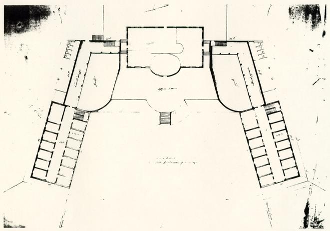 Figure 53
Plan showing Charles Bulfinch's additions onto the Barrell Mansion, which became the McLean Asylum. (McLean Hospital) (CWF #86-414)
61
Assembly's act requiring that full-time superintendents of state hospitals also be physicians (Fig. 54). This progressive step in legislation was more than equalled by the professional dedication and leadership which the young Dr. Galt brought to his field of medicine. Norman Dain's Disordered Minds and Shomer Zwelling's Quest for a Cure describe in much more detail the personality, practice and influence of Galt. Inspired by his own 1843 tour of nine American hospitals and from the current medical works on insanity that he had ordered from Europe, Galt sought to update the appearance of his institution for both medical and aesthetic reasons. In 1843, for example, halfway through the construction of the east wing addition to the original 1770 building, Galt ordered cast iron sashes, one of the hallmarks of Moral Management, for the new building and as replacements for the older window "gratings" in the existing buildings (Fig. 55). To upgrade the expanding complex stylistically, Galt ordered large Greek Revival Doric porticoes in 1845 for the front of the original Public Hospital building and for its flanking advanced wings (Fig. 56). Galt commissioned artist T. C. Millington to capture the hospital's new image in a lithograph the same year (Fig. 57).
The first major buildings constructed under the complete direction of Galt demonstrated a masterful solution that followed advanced theories of treatment and also respected the already established pattern of physical growth. Two buildings were begun in 1848: one for the convalescent and quiet males and
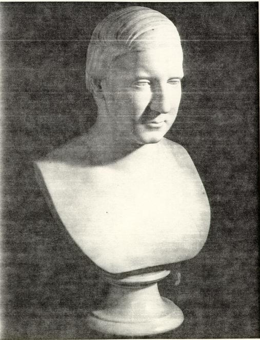 Figure 54
John Minson Galt II. (CWF #84-FD-2207)
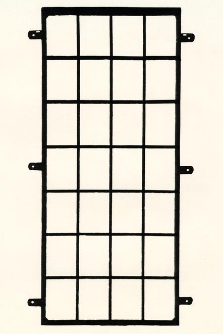 Figure 55
Cast iron sash from Eastern State Hospital Excavated by Ivor Noël Hume.
 Figure 56
Public Hospital ca. 1845. Greek Revival portico and a third floor added by John Minson Galt II. Drawing by James F. Waite based on the 1869 photograph.
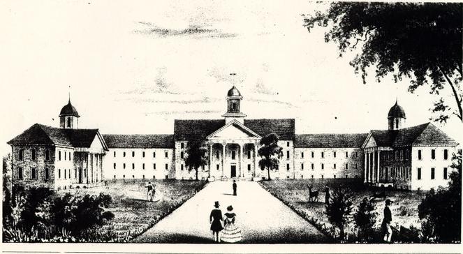 Figure 57
Eastern State Hospital by Millington, 1845. (CWF #70-988)
62
one for violent and "colored males." The separation, or "classification," of cases by severity of disorder was a common practice. Galt decided to place the quiet males' building, called the "Doric" building, to the north as a detached extension of the advanced wing; its Greek Revival classicism fit comfortably with the Greek Revivalized existing buildings (Fig. 58). The violent males, on the other hand, were placed to the south of this ordered classical complex in a "Gothic" building distinguished by two ninety-foot high towers (Fig. 59). This separation was necessary for reasons of treatment, but the use of a very different style infers a symbolic distinction as well. This pattern was duplicated with the construction in 1854 of a "Jacobean" building (Fig. 60) to the south of the main complex for "colored patients," while the female patients were to get a classical building corresponding to the men's "Doric" building; the female building was proposed in 1855 but not constructed until 1883. From Francis Street these additions and alterations presented to the public a visual image of a well-ordered, cohesive architectural ensemble.7 Galt had thus unified the public face of the hospital by the application of Greek Revival facades to the preexisting Georgian and Federal buildings and then continued that stylistic unity in later additions. This renovation was not entirely an aesthetic consideration. Galt felt that a patient's first view of the hospital was significant. He stated that "impressions of the insane mind on entering an asylum, are sometimes of the utmost consequence; on their nature
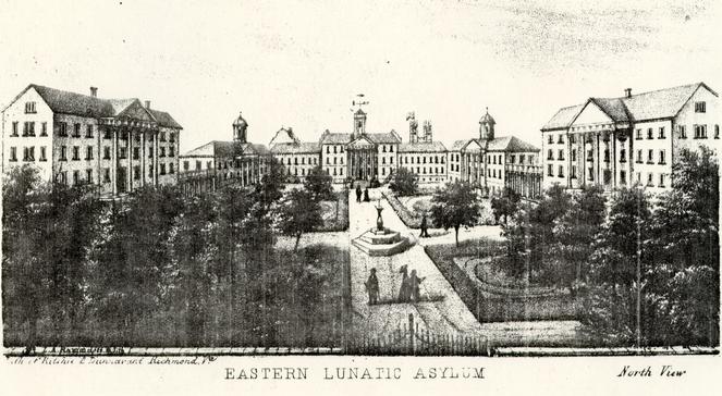 Figure 58
Eastern State Hospital, shown here in 1866 in a lithograph by Ramn. The building on the left in the foreground was planned at this time but not constructed until 1883. (CWF #73-1362)
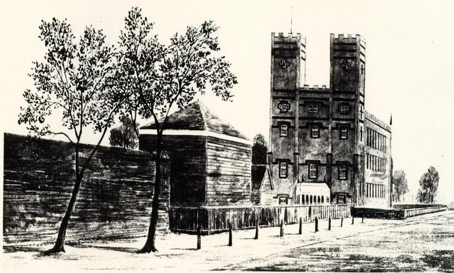 Figure 59
Watercolor ca. 1860 of the "Gothic Building" by Lefevre F. Cranstone. (CWF #N4008)
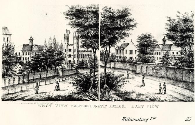 Figure 60
Views by L. A. Ramn about 1855 showing the 1820s-30s additions (with cupolas), the "Gothic Building" and the "Jacobean Building." (CWF #74-697)
63
may depend the event of the case, whether the patient shall henceforth be lost in darkness of insanity, or shall regain the light of a rational mind."8
Galt wanted to create an institutional world of the sane for his patients, an environmental setting that removed patients from the physical or social conditions that may have caused their illnesses. This form of environmental treatment had its roots in Moral Management theories and became widespread among the asylum superintendents in Jacksonian America. David Rothman notes this to be a social cause-and-effect:
64 Designing a proper hospital setting along Moral Management lines was advocated and described in early publications such as Andrew Duncan's Observations on the Structure of Hospitals, in 1809, architect William Stark's Remarks on the Construction of Public Hospitals for the Cure of Mental Derangement, 1810, and Samuel Tuke's Description of the Retreat, published in 1816 (Figs. 61-63). Galt's library contained a number of later books on the same subject, including: William A. Browne, What Asylums Were, Are, and Ought to Be, 1837, John Conolly, The Construction and Government of Lunatic Asylums and Hospitals for the Insane, 1847, and Maximilian Jacobi, On the Construction and Management of Hospitals for the Insane, 1841. Galt was also certainly familiar with Thomas Kirkbride's 1847 article, "Remarks on the Construction and Arrangement of Hospitals for the Insane," which appeared in book form in 1854. Many of these treatises dealt with the construction of completely new facilities, such as Kirkbride's model asylum with its stepped-back wings (Fig. 64). Galt, of course, was constrained by the preexisting buildings and the limited size and location of the hospital property. Nevertheless, he rehabilitated the older buildings and more than doubled the hospital's acreage, although the in-town site never resembled the country setting prescribed in so many of the treatises. Western State Hospital also upgraded its original 1828 facade by the addition of three Greek Revival porticoes, which served to unify the original building with its additional building from the 1830s and 1840s (Fig. 65).The institution itself held the secret to the cure of insanity. Incarceration in a specially designed setting, not the medicines that might be administered or the surgery that might be performed there, would restore health. This strategy for treatment flowed logically and directly from the diagnosis of the causes of the disease. Medical superintendents located its roots in the exceptionally open and fluid quality of American society. The American environment had become so particularly treacherous that insanity struck its citizens with terrifying regularity.
One had only to take this dismal analysis one step further to find an antidote. Create a different kind of environment, which methodically corrected the deficiencies of the community, and a cure for insanity was at hand. This, in essence, was the foundation of the asylum solution and the program that came to be known as moral treatment. The institution would arrange and administer a disciplined routine that would curb uncontrolled impulses without cruelty or unnecessary punishment. It would recreate fixity and stability to compensate for the irregularities of the society. Thus, it would rehabilitate the casualties of the system. The hospital walls would enclose a new world for the insane, designed in the reverse image of the one they had left. The asylum; would also exemplify for the public the correct principles of organization. The new world of the insane would correct within its restricted domain the faults of the community and through the power or example spark a general reform movement.9
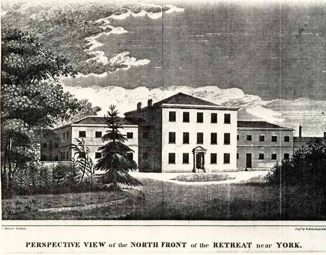 Figure 61
The York Retreat, England. From Tuke's A Description of the Retreat. (CWF #84-1996)
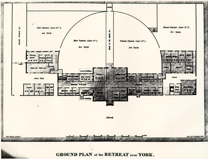 Figure 62
York Retreat, ground plan. From Tuke's A Description of the Retreat. (CWF #84-1996)
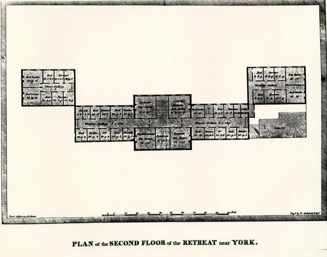 Figure 63
York Retreat, second floor plan. From Tuke's A Description of the Retreat. (CWF #84-1996)
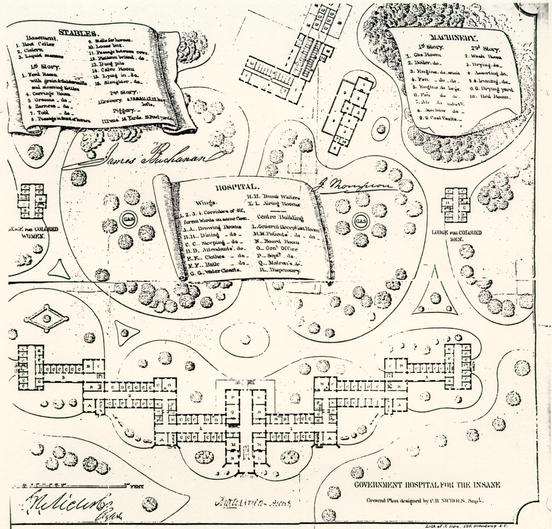 Figure 64
St. Elizabeth's Hospital, Washington, D. C. showing a typical swept-back "Kirkbride Plan." (St. Elizabeth's Hospital) (CWF #84-TS-1840)
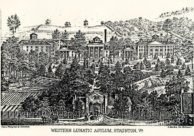 Figure 65
Western State Hospital in the mid=nineteenth century showing the addition of Greek Revival porticoes onto the original building. The buildings to the left and right date form the late 1830s -1840s. (WSH Annual Report, 1873) (CWF #86-411)
John M. Galt II died in 1862 just as Civil War battles raged around Williamsburg. A series of civilian and military superintendents and a shortage of supplies brought the patient population down to 180 (the 1858 population had been 274) and the buildings to a "debilitated and deranged condition."10 Normalcy was postponed even further as the hospital suffered through a post-war period of corrupt directors (Fig. 66).
By the early 1870s, the hospital seemed once again in an expansionist era (Figs. 67-68). The original 1772 building, in addition to being greatly altered, had been principally adapted for non-patient use, as described in this earlier 1872 remodeling account:
The first story now contains the administrative offices--a room for the Directory, a Superintendent's office, Reception room, Steward's office, Assistant Physician's room, and Dispensary; the second story, sitting rooms and bedrooms for the officers; and the third story, dormitories for female patients of the second class.11South of the original building a new building containing a kitchen, bakery, storeroom, chapel, amusement hall, and library was completed in 1872, only to be destroyed in a fire four years later. The building which replaced it in 1881 housed only male patients, however. A new building for female patients on the east range of the extended north wings finally completed the 1855 symmetrical north range scheme planned and depicted in the 1855 lithograph (Fig. 56). Things seemed to be back on a smooth track: a 160-acre farm to the south was added to the hospital property in the late 1860s; steam heating and ventilating systems
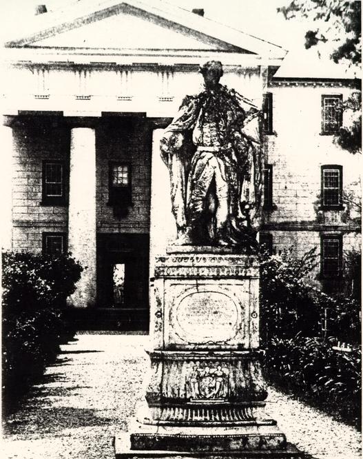 Figure 66
North elevation of the original Hospital building, ca. 1862-64. Alterations include the addition of a third floor, scored stucco, and a Greek Revival portico and cupola. the statue of Lord Botetourt was moved to the Hospital from the College during the Civil War. (CWF #N-6670)
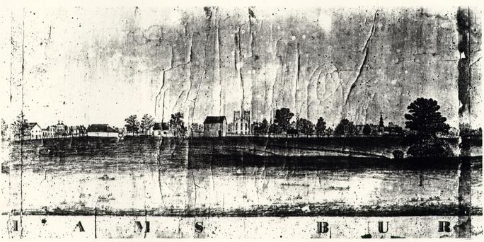 Figure 67
Drawing of Eastern State Hospital from the south by John Graham (a patient) ca. 1859-1862. (CWF #46-W-121)
Figure 68Unidentified persons, presumably Dr. D. R. Brower and staff in front of the Hospital. From a photograph in the Galt Collection, Swem Library, College of William and Mary. Photograph dated 1874 on its reverse. 66 were installed in the buildings in 1872; a bake house, oven, carpenter's shop, and two kitchen/storehouses were added in 1878; two infirmary wards were created in 1882-83; an amusement hall was constructed in 1882 at the north edge of the east range near Francis Street; several buildings were remodeled or expanded in 1884-85; and electric lights were installed and operating by January 1885 (Fig. 69). Ironically, the most modern of the improvements, electricity, was held responsible for a fire on the evening of June 7, 1885. This fire destroyed the original 1773 hospital building and its 1820s-40s wings, or what the superintendent described as "half the asylum" (See Account of Fire, Appendix D) (Figs. 70-71). The absence of fire engines in Williamsburg, and the reliance on those sent from Richmond, resulted in the complete destruction of the building and its flanking wings.
Nevertheless, Eastern State Hospital's physical expansion continued for the remainder of the nineteenth century and into the twentieth. After the fire, the walls of the original 1773 building were dismantled to their foundations and the site covered with earth. Before the year was up, a new administration building was constructed just to the south of the 1773 building site (Fig. 72). The later nineteenth-century buildings were eclectic in style and reflective of the postwar custodial care era (Fig. 73).
Although new buildings replaced those which had burned, the basic problem of providing custodial care for four to five
 Figure 69
South Elevation of the original building in the year of its destruction, 1885. The pediment and cornice are believed to be reused form the 1771-1773 construction. A later wire lighting conductor can be seen leading to the location of the original ground. (CWF #69-396)
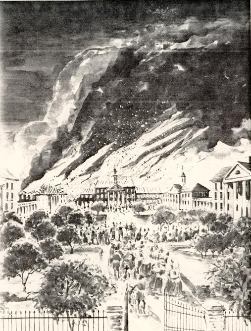 Figure 70
A depiction of the fire of June 7, 1885 by Richard J. Stinely. (CWF #85-FD-163)
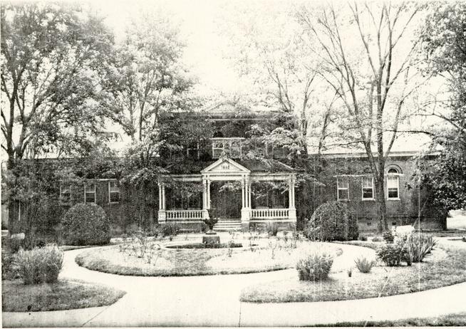 Figure 71
1885 Administration Building constructed just north of the original Hospital building site. (CWF #AL-81)
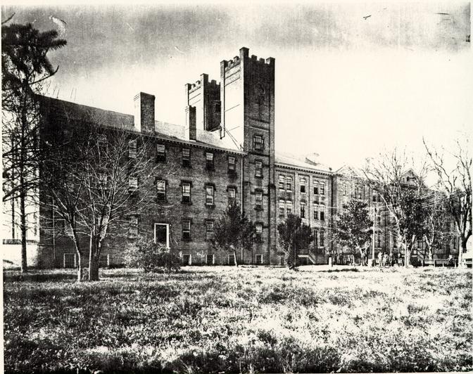 Figure 72
The "Gothic Building" of 1848-1850 with its addition of 1883. (CWF #85-324)
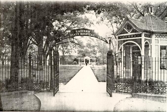 Figure 73
Principal entrance to Eastern State Hospital showing the 1885 Administration Building and late nineteenth-century gatehouse.. (CWF #AF-123)
67
hundred patients was enormous. Any architectural innovation related to treatment was more likely to be the result of general building technology than physician input. In the 1890s there were repeated statements by the superintendent that inappropriate and incurable patients filled the hospital. Dr. Moncure's 1893 annual report indicates that the environmental model had given way to one strictly medical, one on which he pinned his hopes:
While I believe that everything possible has been done for the welfare and the comfort of the patients committed to your care with the limited means at your disposal, I have long felt that the magnitude and great prevalence of this disease throughout all civilized countries demands that these hospitals should be placed on a more thorough basis for the minute and careful study of this disease. Every modern hospital should have a trained pathologist attached to it, and whenever the medical staff deem it necessary they should have a legal right to make post-mortem examinations. These specimens should be carefully observed, their abnormal condition annotated, and the symptoms exhibited during life compared with lesions determined after death. From such study alone can progress in the treatment of insanity be expected.12
The Williamsburg institution officially expressed the end of the asylum era in 1893 by changing its name from Eastern Lunatic Asylum to Eastern State Hospital (Fig. 74). For the first half of the twentieth century "state hospital" connoted custodial care. New therapeutic trends eventually followed custodial care: sanitariums, clinics, individual psychotherapy, milieu therapy, and networks of community-based services. Fundamentally, the emphasis has slowly switched in this century from institutions to people and human behavior as the principal agents affecting treatment. Since the 1960s the emphasis on the community as a means of treatment, and the hopes committed
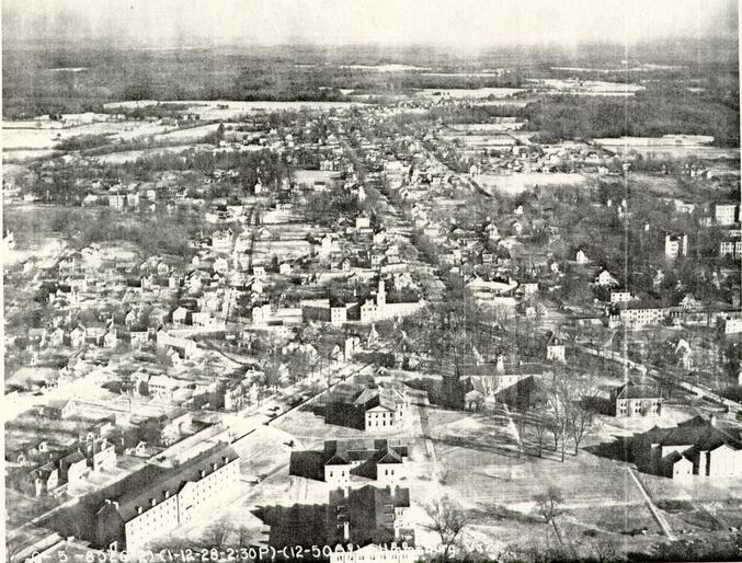 Figure 74
Williamsburg in 1928 showing the Eastern State Hospital complex to the center right. (CWF #79-1400)
68
therein, represent another shift and perhaps another era of treatment for the mentally ill. There have been many changes in hospital architecture during the past century in accordance with various techniques and technologies. The history of a hospital demonstrates, however, that its architectural form, as well as any changes to that form, generally has been associated with prevailing theories of treatment.
CHAPTER VI
NOTES
CHAPTER VII
COLONIAL WILLIAMSBURG AND EASTERN STATE HOSPITAL,
1928-1969
As the third quarter of the eighteenth century drew to a close, so did the glory that was Williamsburg's. With the breakdown of colonial rule in 1779 and the removal of the newly formed state government to Richmond in 1780, the Public Hospital was left as a cultural high water mark in a town abandoned to suffer the epitaph of former capital. Fortunately for Williamsburg, two institutions had been established that did not require the functions of a capital for their existence. These legacies, the College of William and Mary and the Public Hospital, continued to grow in the nineteenth century and both probably helped save Williamsburg from a fate similar to that of Jamestown (Fig. 75). Although it was the newer institution of the two, the Public Hospital, which eventually became known as Eastern State Hospital, actually grew much larger than the college and, even as late as the mid-twentieth century, its name was synonymous with that of the town. The college and the hospital were frequently associated and inevitably joked about, as in the reported difference between the two being the requirement that at the hospital one had to show progress in order to leave.1 Interestingly, it is the twentieth century association of the two that bears most heavily on the reconstruction story.
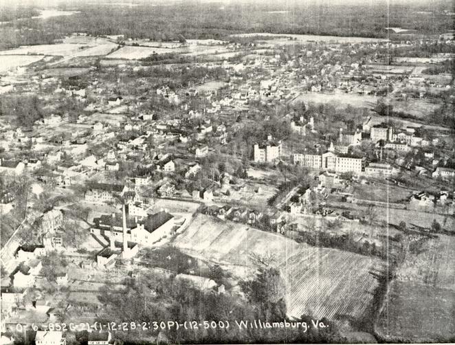 Figure 75
The scale of Eastern State Hospital, center right, clearly dominates the town in this 1928 photograph. (CWF #79-1407)
The first documented reference to reconstructing the Public Hospital as part of the restored town dates to the very beginning of the restoration effort. Not surprisingly, this idea came from the Reverend William A. R. Goodwin, who, through his conception of a restored town, had secured the financial backing of John D. Rockefeller, Jr. Writing from the Wythe House to one of Rockefeller's organizers on February 3, 1928, Goodwin mentioned that it was Eastern State Hospital Superintendent Dr. George W. Brown who had first attempted to find funds to "restore" the original hospital building, which had been destroyed in 1885. Dr. Brown had been discouraged by the lack of interest, lamenting that "people of means give enumerable buildings to Colleges, but seldom any to lunatic asylums."2 Goodwin suggested asking "Mr. David" [Rockefeller] for the funds to "restore" the hospital and at the same time acquire the colonial Galt Cottage and some land from Eastern State Hospital. Goodwin suggested that a reconstructed facade be added to the existing 1885 administration building, which had been built just south of the original building's site. By doing this, Goodwin concluded, "we would then have included in our plan of restoration the first College building in America, the first Capitol, the first Palace, (as far as I know), the first English incorporated city in America, and the first building for the exclusive care of the insane … ."3 Nothing came of this initial scheme, but it was the beginning of probably the longest 73 effort by Colonial Williamsburg to acquire a historic site in Williamsburg.
By the early 1930s, the realities of modern life had encroached upon the increasingly inviolate character of Colonial Williamsburg's historic district. Ironically, Eastern State Hospital, which had helped sustain the town through its declining years, became a thorn in the side of restoration effort. This first became apparent in 1933, when Eastern State announced plans to build workers' houses on land south of Francis Street and opposite King Street, an extension of the vista created for the newly reconstructed Governor's Palace (Fig. 76). Sympathetic hospital officials were persuaded not to build on the land, but refused to sell it, citing the need for a buffer zone to the east of the complex. In the following year a much more serious problem presented itself. After selecting a location for the much needed Williamsburg Lodge, Foundation officials discovered that screams of hospital patients could clearly be heard at the proposed site. The suggested solution involved removing the noisy patients to a 500 acre farm known as Dunbar, two miles outside of town, which was owned and used by the hospital for occupational therapy. To aid in this cause, the chairman of the State Commission on Conservation and Development was invited to Williamsburg. Spending a sleepless night because of "shrieks and yells and hideous laughter," William E. Carson gave a statement to the press which referred to the increasing realization that Colonial Williamsburg was a valuable tourist asset. "Tourists,"
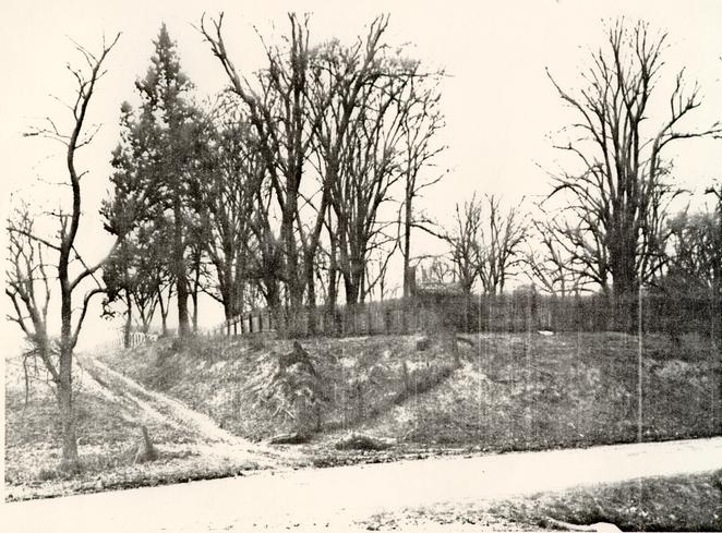 Figure 76
Francis Street and the northeast edge of Eastern State Hospital property. The area to the left of the fence was the proposed site for workers' houses. (CWF #UN 687)
74
Carson said, "are not inclined to spend the night in the vicinity of a mad house."4 With a $25,000 contribution from Colonial Williamsburg for two new buildings at Dunbar, the state legislature was persuaded by the governor to pass an act in 1936 which called for the removal of 250-300 noisy patients from the city to the farm site. In accepting the gift, the hospital agreed to a gradual removal of all in-town facilities to a new modern hospital complex which, by all accounts, was clearly needed. In the meantime, the hospital agreed not to build any major additional structures in Williamsburg.
By 1945 the capacity for housing noisy patients at Dunbar had been reached. For the next six years occasional guests staying at the Williamsburg Lodge occasionally complained of sleepless nights brought on by "howling," which reiterated the fact that the noise problem still remained. In his naivete, John D. Green, manager of the Williamsburg Inn, even wrote to Kenneth Chorley that the patients' screams were "particularly bad during the period of the full moon."5 one visitor wrote in 1953 that the proximity of the hospital to the Historic Area was "truly disgraceful," and that "Here within a few blocks of the Governor's Palace showing such gracious living so long ago is modern America--a truly rude awakening to reality."6 Feeling that the construction of the new complex had been tied up in state financing, Colonial Williamsburg initiated a radical proposal to accelerate the removal of the old hospital buildings in town. Colonial Williamsburg was willing to loan the state $23 75 million dollars at a low interest rate to complete construction of the new hospital complex. The press soon brought this controversial matter before the public in a long series of editorials and articles. The issue came to an abrupt halt when it was learned that the College of William and Mary, to whom the deed of hospital land had been conveyed in 1945, was not willing to sell any of the 207 acres to Colonial Williamsburg, stating that the land was needed for campus expansion. This turn of events led Colonial Williamsburg to withdraw its offer and all hope was lost for a speedy completion of the new hospital complex. At this time, approximately one-third of the 2,200 hospital patients had been transferred to the Dunbar site, prompting one newspaper article to state that Eastern State was suffering from schizophrenia: "The hospital's personality is distinctly split: On the one hand, old and shabby; on the other, new and shiny. It creates a situation as crippling to the life of the institution as the disease is to ailing patients."7 With legislative pressure, the college finally agreed to sell the immediate site of the original hospital, about 11 acres, to Colonial Williamsburg (Fig. 77). Nevertheless, negotiations broke down and any further preparation at the Dunbar site stalled for about five more years.
By the end of 1959, appraisers selected by both Colonial Williamsburg and the college had evaluated one parcel of land (1.96 acres) north of Francis Street between Henry and Nassau Streets on which the Travis House stood and a parcel
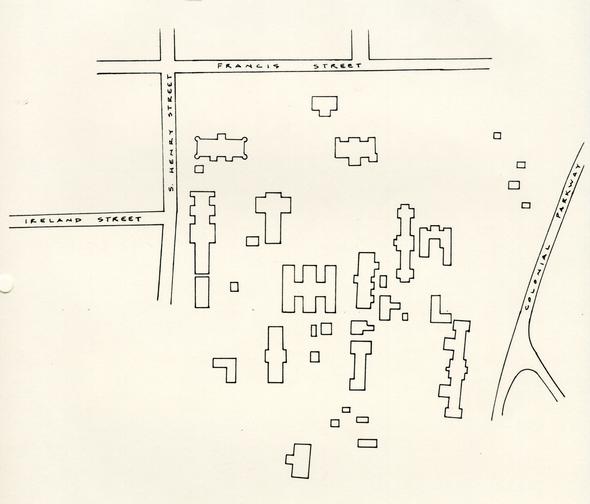 Figure 77
The extent of Eastern State Hospital buildings ca. 1960. (TCM)
76
(13.73 acres) south of Francis Street between Henry Street and the Colonial Parkway. The smaller of the two parcels was appraised for $116,400. This parcel was authorized for sale or exchange by the House of Delegates in March and conveyed in July 1960.8 The larger parcel of 13.73 acres, having been reappraised for $180,000, was not purchased immediately.9 In the meantime, Colonial Williamsburg requested the purchase of an additional 8.71 acres for a new courthouse site adjacent to and north of the 13.73 parcel.10 Four years lapsed and finally, in the fall of 1964, both the 13.73 acre parcel and the 8.71 acre parcel were authorized for sale to Colonial Williamsburg for $383,600 and $288,000 respectively.11 Events proceeded rapidly after title to the land was conveyed in March 1966. Five structures in "Area A", the site of the new courthouse, were demolished the following month. The next area cleared was that of the reconstructed hospital and Wallace Gallery site north of the courthouse, consisting of the 1885 Administration Building, which had been turned into an infirmary, the Thompson (Fig. 78) and Thurman buildings, and connecting arcades. By April 1968 "Area C's" twelve buildings were demolished. This area north of Newport Avenue (formerly Tazewell Hall Street) and east of the new courthouse site was cleared to make way for the extension of Nassau Street, which was necessary as an access for the new courthouse. The last area to be demolished was "D", between Newport, Henry, Nassau and Court Streets.12 The Cameron Building in "Area B", used for the Fife and Drum Corps between 1964 and
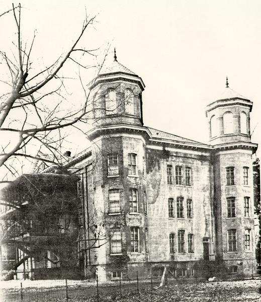 Figure 78
Thompson Building. By the 1960s structures like this from the "Custodial Care" ear were the oldest survivors at Eastern State Hospital. (CWF #66-SMT-575)
77
1969, was actually the last building to go. By the fall of 1969 the intrusive realities of mental illness no longer distracted visitors to the Historic Area and the former hospital site was a tabula rasa for its anxious new owners.13
CHAPTER VII
NOTES
THE PUBLIC HOSPITAL:
AN ARCHITECTURAL HISTORY AND
A CHRONICLE OF RECONSTRUCTION
Architectural Research Department
Colonial Williamsburg Foundation
Williamsburg, Virginia
1986
VOLUME II
| Chapter | Page | |
|---|---|---|
| XIII | Plans for Reconstruction | 80 |
| IX | Archaeology | 85 |
| X | Design Methodology | 88 |
| XI | Brick | 94 |
| XII | Cellar Vents | 111 |
| XIII | Bulkhead | 113 |
| XIV | Water Table | 119 |
| XV | Cellar Windows | 126 |
| XVI | Stairs | 133 |
| XVII | Doors | 149 |
| XVIII | Windows | 157 |
| XIX | Arches | 170 |
| XX | Beltcourse | 177 |
| XXI | Cornice | 179 |
| XXII | Pediment | 187 |
| XXIII | Roof | 192 |
| XIV | Chimneys | 196 |
| XXV | Cupola | 203 |
| XXVI | Weather Vane | 217 |
| XXVII | Lightning Conductor | 247 |
| XXVIII | Exercise Yards | 274 |
| XXIX | Grounds | 298 |
| XXX | Interior | 303 |
| XXXI | Eighteenth-Century Passage and Cell | 311 |
| XXXII | Nineteenth-Century Cell | 326 |
| XXXIII | Lumber | 334 |
| XXXIV | Nailing Patterns | 338 |
| XXXV | Hardware | 339 |
| XXXVI | Construction | 358 |
| XXXVII | Grime and Graffitti | 364 |
CHAPTER VIII
PLANS FOR RECONSTRUCTION
1928 - 1981
The earliest documented reference to reconstructing Eastern State Hospital's original building was Reverend Goodwin's letter of 1928, cited in the previous chapter. After this time, little if nothing was said publicly concerning the issue, due to the lengthy campaign to acquire the property. It was not forgotten, though, no matter how tenuous the property acquisition may have been. On the first of January, 1950, Kenneth Chorley submitted a report to John D. Rockefeller, Jr. estimating the cost of completing the "physical restoration of Colonial Williamsburg."1 Included in this report was the "Maison des Foux," whose reconstruction was estimated at $325,000. Still, Chorley was publicly silent on any plans for reconstruction, telling the Newport News Times-Herald in 1953 that Colonial Williamsburg "at this time has no definite plans for the use of the Eastern State site, nor any plans in the making." The only definite statement he could make was that the corporation should acquire the property as a protection to the restored area.2
By the end of the decade the battle with the College and the state had been won. The newspaper headlines could now state "Officials Urge Rebuilding of old Lunatick Hospital."3 Nevertheless, there were few tangible signs of a reconstruction plan in the 1960s other than the demolition of old hospital 81 buildings. A. Edwin Kendrew calculated usable space in the Public Hospital in a memorandum to the files in 1965 and Carlisle H. Humelsine asked for the rough cost of reconstruction in 1968, but any immediate plans were not forthcoming.4 Dr. Ashbury of Eastern State Hospital requested that the hospital be reconstructed by 1973 in order to coincide with Eastern State's bicentennial celebration. After considering the feasibility of this proposal, the Restoration and Reconstruction Committee decided that a crash program of research and archaeology would be too disruptive for previously established schedules.5
Significant events occurred in the 1970s, paving the way for the eventual reconstruction of the hospital in the following decade. In March 1971, Director of Architectural Research Paul Buchanan submitted a report, "A Proposal for the Reconstruction of the Maison Des Foux," in which he recommended to the board of trustees two schemes for reconstruction. The larger of the two schemes (18,700 sq. ft.) called for exhibition space in the roofed over exercise yards. Both schemes advocated only an exterior reconstruction; an interior reconstruction was regarded as "problematic."6 Archaeological investigation, recommended in the 1971 report, began on the original hospital site in 1972 under the direction of Ivor Noël Hume.7 At about the same time, an in-depth documentary research report was begun by Patricia A. Gibbs and Linda H. Rowe and conjectural floor plans and elevations were worked out by Paul Buchanan and James F. Waite. Two other coinciding events then took place in 1976 82 and 1977. In 1976 Carlisle H. Humelsine secured the donation of $4 million from DeWitt Wallace for a new theater in which to show "The Story of a Patriot." The following year Humelsine committed the Foundation to reconstructing the hospital, with a first floor devoted to interpretation and the second floor housing the Research Department.8 While these two events were not originally linked, a decline in visitation caused the postponement of the theater project in 1979 and, consequently, the reapplication of the Wallace gift to a decorative arts museum contained within the reconstructed exterior of the Public Hospital.9 A press release in November 1979 announced the project to the public.
The initial scheme in 1979 called for two phases of building: the first involving the hospital building and an undetermined underground space to the north and the second the building of brick exercise yard walls to conceal still more space. The amount of space and discussions about the desired facilities then began an evolution in conception and design focus. By February 1980, the Wallace Decorative Arts Gallery Planning Committee10 reported that the building and yards would constitute a single phase of construction and "a large underground area to the south and contiguous with the reconstructed hospital (main building) be designed now for later construction…."11
By spring, the architectural firm of Roche Dinkeloo and Associates, chosen by the Wallaces, was taking a critical look at fitting the required functions into the allotted space. The 83 future underground addition to the south began to appear more frequently into the discussions. Kevin Roche proposed four schemes that he presented in June.12 Two schemes took advantage of roofed-over exercise yards, with a smaller underground addition to the south. The other two presented no exercise yard space but a quadrupled underground area to the south. The larger of the second schemes was chosen; it put the Public Hospital in the role of entrance to the larger decorative arts museum (Fig. 79). Even though this scheme escalated the cost dramatically, the Wallaces gave their enthusiastic approval.
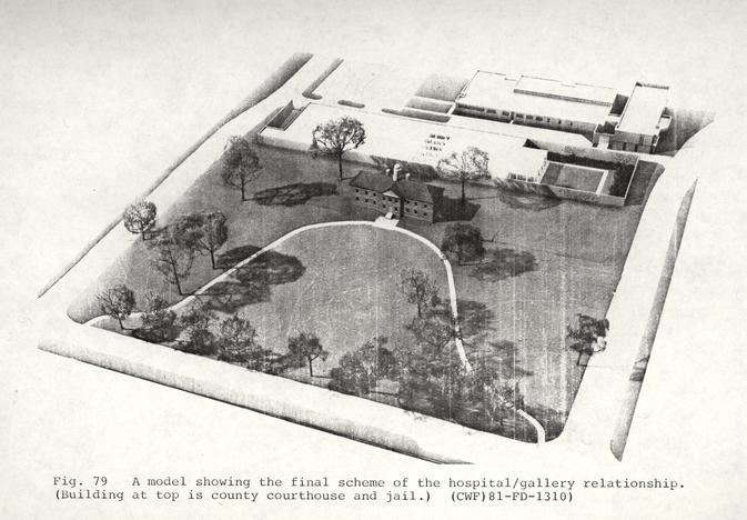 Figure 79
A model showing the final scheme of the hospital/gallery relationship. (Building at top is county courthouse and jail.) (CWF) 81-FD-1310)
CHAPTER VIII
NOTES
CHAPTER IX
ARCHAEOLOGY
Archaeological excavations were first conducted on Eastern State Hospital property in 1963 when hospital officials gave permission to Colonial Williamsburg to record the Custis lot (Fig. 80). Following that, salvage archaeology took place in 1966 on the site of the new courthouse and jail, land that had been part of the hospital property. It was not until 1972, however, that excavations were started on the original hospital building-site.
Architecturally, the original building yielded no great surprises, other than the fact that only the central pavilion contained a cellar (Figs. 81-82). Three additional cellar cells, documented in hospital records to date to ca. 1799, were also found. Otherwise, the foundation walls revealed the building as designed by Robert Smith and presented in his "Description." The principal room in the cellar, 13' x 21'-2" in dimension, showed evidence of use as a kitchen. This room was separated from the staircase and a small north cellar room by an east-west partition wall. The bulkhead entrance to the cellar was also located on the south. For the most part, the 1773 building contained valuable artifactual information about its late nineteenth-century use.1 The most surprising find, unrelated to the hospital, was the remains of two seventeenth-century house sites, one of which was believed to have been Governor Francis
 Figure 80
Archaeology at the Custis site east of Nassau Street. (CWF 64-INH-4469)
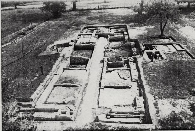 Figure 81
Public Hospital foundations excavated in 1972-1973. (CWF 72-FD-879)
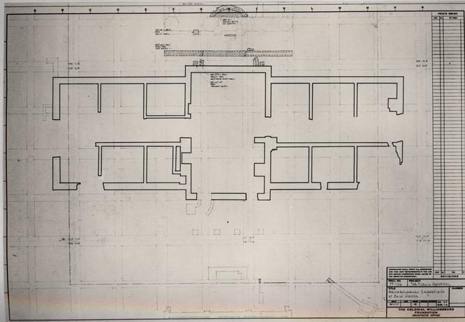 Figure 82
Public Hospital. Drawing of excavated foundations (James F. Waite). (CWF 81-DS-2714)
86
Nicholson's dwelling (Fig. 83). Based on the archaeological work carried out under the direction of Ivor Noël Hume, a conjectural picture of the original hospital building began to emerge. James F. Waite and Paul Buchanan were able to interpret the archaeological findings in concert with written documentation and to produce drawings of the building. This process was documented by James F. Waite in "Architectural Notes on First Preliminary Drawings," December 1972.
When plans for the Wallace Gallery developed in 1979, additional archaeological excavations were scheduled in order to record the exercise yard areas flanking the original building and the remainder of the site to the south where the gallery would be located. This final period of archaeology started in 1980 and continued until January 1983. The most significant early structures found during the second period were the 1805 Convalescent House, a late eighteenth/early nineteenth-century kitchen, an 1825 kitchen complex, and a small outbuilding on the edge of the ravine (Fig. 84). Parts of the site were never fully excavated due to the construction schedule. Perhaps the most important of these was a centuries-old ravine dump site, where a small crew of excavators briefly conducted salvage archaeology.2
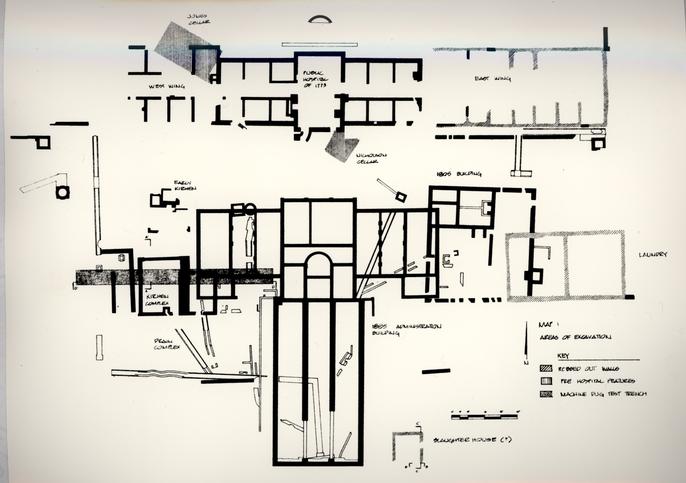 Figure 83
Full extent of archaeological excavations. (CWF 86-370)
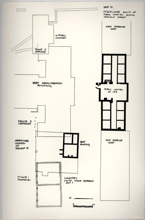 Figure 84
Archaeological excavations in area just south of the original building. (CWF 86-375)
CHAPTER IX
NOTES
CHAPTER X
DESIGN METHODOLOGY
The design phase of the project effectively started on June 3, 1981, with the first meeting of the Public Hospital Design Review Committee. Three weeks prior to that meeting, Travis C. McDonald, Jr. had been hired as a consultant to collect and reevaluate previous research and documentation and to write a documentary report on the design decisions. Eventually, he became a staff member with the title Architectural Coordinator, whose scope of duties included providing research, directing the weekly design review meetings, coordinating various persons working on the project, supervising the construction, and ultimately, chronicling the project's history.
The Public Hospital Design Review Committee was formed under the direction of Roy E. Graham, Resident Architect, at the suggestion of Edward Chappell, Director of Architectural Research. Its purpose, briefly, was to evaluate research, formulate design, and generally to pass judgment on the reconstruction. Committee meetings were held once or twice a week for the early design phase of the project and about twice a month, or as need arose, for the remainder of the project. Committee meetings were recorded in the form of minutes, which remain a valuable source beyond this report for the rationale directing decisions and the interaction of the committee members 89 through their address and resolution of research questions and design problems. These minutes have been indexed by subject.
The design methodology involved approaching the building according to individual elements and considering them for design review in a sequence determined by the working drawings schedule. In most cases the basic architectural element was known, through either documentary sources or typical construction practices, but its details generally required much further research. The philosophy governing the committee's decisions revolved around known, documented, factual information. Information from Robert Smith's "Description" and Benjamin Powell's contract was used whenever possible. Other important sources were hospital records, historic visual material, and archaeological information. Certain items in each of these three categories were indispensable to the reconstruction and served as constant research "touch stones." In the first category was the 1974 Public Hospital research report by Patricia A. Gibbs and Linda H. Rowe, an unimpeachable guide to documentary data. This rich compilation of material blends together valuable primary and secondary source material in a chronological format. The most pertinent sources drawn upon in the Gibbs/Rowe report are the Journal of the Virginia House of Burgesses, the Court of Directors' Minutes of Eastern State Hospital, the Virginia Treasurer's Office Records, the collections of papers of various directors and trustees, and the Virginia Gazette. The report covers the period 1766-1885 with a gap of missing directors' 90 minutes from 1801-1822. The most important documents in the visual category were two historic photographs of the hospital, showing the north elevation in 1869 and the south elevation in ca. 1885, and the ca. 1829 drawing ascribed to Keeper Dickie Galt, the project's "Bodleian Plate." The most significant archaeological artifact was the original hospital foundations themselves. James F. Waite's 1972 report, "Architectural Notes," offered an important architectural interpretation of the foundations as they related to the principal historical documents of construction.
The committee felt that for undocumented elements or details, local original examples, as opposed to details from extant Robert Smith buildings in Philadelphia, should serve as prototypes. Williamsburg buildings frequently consulted were the Courthouse of 1770, Bruton Parish Church tower, the Palmer House, the President's House, Brafferton Hall, and the Public Records Office. Other buildings in the state also provided prototypes for various details: Carter's Grove, the Nelson House at Yorktown, Berkeley, Shirley, Tuckahoe, Mt. Airy, Strawberry Hill in Petersburg, Blandfield, and other buildings recorded as part of the Agricultural Buildings Project. Western State Hospital in Staunton was the principle source for the hospital's nineteenth-century details.
Design elements were presented to the Design Review Committee and, upon their approval, the details were transmitted to James S. Tuley and Fred Schneider in Charlottesville, 91 architects under contract for the working drawings. In most cases the proper details were first drawn by James F. Waite in the Colonial Williamsburg architectural office and then transmitted to Tuley for conversion into working drawings. In many cases an element or detail needed further research or clarification and came before the committee numerous times. This was especially true of several elements whose design occurred after the completion of the basic set of hospital working drawings, such as the weather vane, the lightning conductor, the exercise yard fences and the various items of door hardware. In such cases, as with the entire set of interior drawings, the drawings were produced in-house by James F. Waite, as they were building parts that fell under the owner's (CWF) responsibility to furnish and/or construct. The general set of hospital working drawings were forwarded to Roche Dinkeloo and Associates and became part of the entire gallery set of contract drawings according to which, with the combined set of specifications, the R. E. Lee Company of Charlottesville successfully bid the job as general contractor.
The Design Review Committee was initially composed of Roy E. Graham, Resident Architect; Edward A. Chappell, Director of Architectural Research; James F. Waite, Architectural Draftsman; Donna C. Hole, Architectural Research Fellow; and Travis C. McDonald, Architectural Coordinator (Fig. 85). Beatrix T. Rumford, Vice-President of Museums and project director of the hospital/gallery project, was an ex officio member. The
 Figure 85
The initial Public Hospital Design Review Committee. Left to right: Roy E. Graham, Travis C. McDonald, Edward A. Chappell, Beatrix T. Rumford, and James F. Waite. The committee is standing in front of the re=excavated Public Hospital foundations. (CWF 82-FD-5532)
92
composition of this group changed in 1982 with the departure of Donna Hole and Roy Graham. Nicholas A. Pappas, Foundation Architect, joined the group and Beatrix Rumford became a sitting member (Fig. 86). Wendy A. Cooper, Director of the Hospital and Wallace Gallery became an ex officio member in 1984. Many other people were frequent guests and participants at the meetings, including Willie Graham, Architectural Research Fellow in the Department of Architectural Research; Ronald J. Catella, Director of Construction Management; Kenneth F. Morris and Charles L. Frank, construction managers for the project; Willard E. Gwilliam, Director of Architecture and Engineering; Donald Parker, Director of Landscape Architecture; Ivor Noël Hume, Foundation Archaeologist; and Shomer Zwelling, Research Historian for the project.
The Agricultural Buildings Project, whose life began simultaneously with the design phase of the hospital project, was of great assistance in the design of many details. Willie Graham of that project deserves much credit for his opinions and advice on many issues, especially those concerning the interior. Douglas Taylor and John Bernard, also from the Agricultural Buildings Project, occasionally helped with specific details. Other members of the Architectural Research Department deserve credit for various aspects of research and assistance: Thomas H. Taylor for his help with bricks, glass and shingles; Wayne Kille for his help with bricks; Mark R. Wenger for his assistance with the cupola studies and for putting together historic nailing
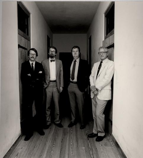 Figure 86
Public Hospital Design Review Committee. Left to right: Travis C. McDonald, Edward A. Chappell, James F. Waite, Nicholas A. Pappas. (CWF 85-FD-1348, 95)
93
patterns for millwork, which became part of the working drawings set; Vanessa Patrick for her shared research and advice on the exercise yard fence; and Carl Lounsbury for his court record references to jails, prisons and lunatics and also for his slides of English weather vanes.
The following section is divided into chapters on each design element. For each element the chapter is arranged into sections comprising description, documentation, prototypes and comments on construction. These sections are further divided and expanded as necessary. The intention is to offer as complete a record as possible for each design decision. It is impossible, of course, to recapture the entire decision-making process. Many discussions and exchanges were spontaneous and survive only in short-term memory. It was felt, however, that choices, and the logic for making choices, should be included in this documentation. It is with this in mind that the present report is written. Observing the historian's cardinal rule, the reader is encouraged to also investigate the primary sources for this report: file notes, memorandums, letters, minutes and site reports. In particular, the minutes of the Design Review Committee and the chronology/site reports by Travis C. McDonald are of importance regarding details, and in many cases, the personal, intimate story of the project.
CHAPTER XI
BRICK
This chapter is a general discussion of field brick. Specific brick design elements such as the water table, jack arches, and belt course will be treated separately. Consult the materials section for a discussion of the reproduction process.
DESCRIPTION
The hand-made brick used for the Public Hospital reconstruction vary in size, with the average being 9" x 4 5/16" x 3". The color ranges from a brownish red to a dark plum, with the rubbed brick a dark red color. Rubbed brick is used at window and door surrounds, at corners, in window and door jack arches, and for the water table and belt course. The struck mortar joints are an average width of 3/8". Partially glazed headers and stretchers occur randomly.
DOCUMENTATION
Robert Smith/Benjamin Powell
Robert Smith's "Description" contained the following reference to brick:
This Building will required about Two hundred thousand Bricks each Brick about 8 ¾ Long 2 3/8 Thick and 4 ¼ Broad about 13 of such Bricks with Mortar will make one foot Superficial of a Nine Inch Wall or 19 ½ of such to a fourteen Inch Wall.1
95In his contract, Benjamin Powell agreed to build the hospital with ". . . well burnt Bricks . . . laid with good Mortar… ."2 The supplier of the brick was Samuel Spurr. Spurr's role as a subcontractor to Powell was presumably that of a brick manufacturer and master bricklayer. Powell and Spurr may have collaborated on other projects, because just after the Public Hospital job we find Spurr providing the brickwork for Powell's extensive repair of the Gaol in 1773.3 Spurr was responsible for the brick wall around Bruton Church in 1752 and may have been the brick subcontractor when Powell built the Bruton Church tower in 1769.4 In any event, Spurr was ready for the hospital project by October of 1771, as his advertisement in the Virginia Gazette indicates:
Williamsburg, October 2, 1771.
The Subscriber will give good Wages, and Accomodations, to two or three Journeymen BRICKLAYERS, for the remaining Part of the Season, to work upon the Hospital building in this City. Plenty of Bricks and Lime is ready, so that they will be no Delay.
SAMUEL SPURR5
Archaeology
The brick color range, size, and bond, as well as the use of glazed brick were determined from the excavated Public Hospital foundations (Fig. 87). An English Bond foundation was also confirmed. By the time the research for the Public Hospital design was conducted during the summer of 1981, the original hospital foundations had been backfilled and other areas of the
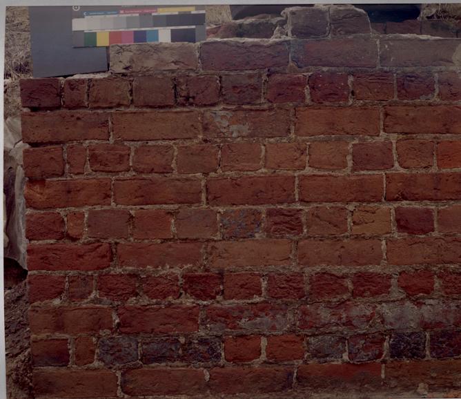 Figure 87
English bond foundation, northeast corner of pavilion. (CWF K82-FD-746)
96
site were being excavated. Only the hospital's north pavilion had been re-excavated in a search for the original stairs. It was this area of the foundation that was cleaned in situ in order to examine the color range and glazing of original brick. Six original brick representing a full color range were removed from this area and cleaned in order to be studied by the Design Review Committee. When compared with the brick of Bruton Church tower and the Courthouse of 1770, five out of the six matched very closely in color and texture, the exception being a very light salmon color brick. Previously, Colonial Williamsburg mason Harry Flythe had removed some foundation brick from the east wall of the hospital and cut and ground them for a color examination. These bricks composed a very light range, leading to the conclusion that clumps of like color were laid in the foundation without regard to appearance.
The average hospital brick size of 3" x 4-4 ¼" x 9-9 ¼" was determined by James F. Waite when he surveyed the entirely exposed foundations in 1972 prior to backfilling. The quality of mortar, the 3/8" joint size and the random use of glazed headers and stretchers were also determined from the north pavilion foundations.
Archaeological excavations of the brick exercise yard wall (1800) revealed that its brick color was different (red-orange) from that of the hospital, as well as a different size (2 ½" x 3 7/8" x 8 ¾).
97In anticipation of site clearance, the entire exterior face of the original foundations, which had been covered since the 1972 excavation, were re-excavated during the summer of 1982 (Fig. 88-89). The purpose for this was to examine the foundation with regard to manufacturing reproduction brick. Not surprisingly, the foundations were composed of a fairly consistent light red-orange brick with traces of a fuller range of dark colors near the top, just below grade on the hospital (Fig. 90). This observation led to the conclusion that the below grade brickwork had, by choice, been constructed with the lighter colors from the brick production by Samuel Spurr.
After documentation through large format color photography, the original foundations were removed from the site and taken to the project dump site on South England Street (Fig. 91). Whereas the brick remains and fill from hospital structures south of the original building were buried, creating a berm at the dump site near the entrance to the Country Road, the original hospital foundation brick were not buried but deposited on the west side of this newly formed hill. In addition, three wooden crates of hospital brick were placed in the Piland Warehouse and a smaller collection was placed in the Architectural Research storage area under the Trellis Restaurant.
PROTOTYPES AND DESIGN
A 1972 survey of the completely excavated foundations revealed an average brick size of 9-9 ¼" x 3" x 4-4 ¼", as
 Figure 88
Re-excavated foundations, north wall. (CWF K82-FD-752)
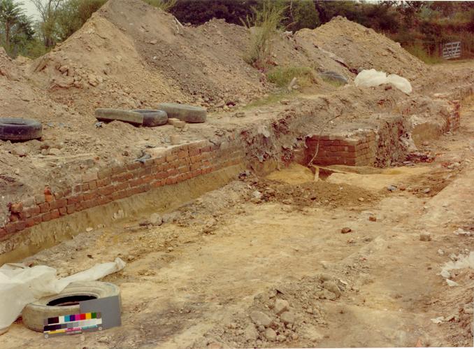 Figure 89
Re-excavated foundations, south wall (note lightning conductor ground).
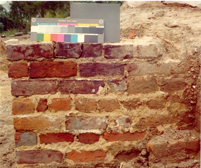 Figure 90
Re-excavated foundations, southeast corner of pavilion. Color and joint indicates rebuilding. (CWF K82-FD-747)
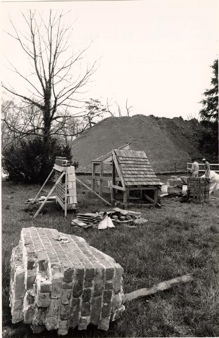 Figure 91
This large section of original foundation wall (foreground) was retained at the site for mortar color comparisons and for brick experiments conducted by the Architectural Conservator. (CWF 83-3067s.TCM)
98
opposed to Robert Smith's specified size of 8 ¾" x 2 3/8" x 4 ¼". The Committee felt that the physical evidence took precedent over the documentary evidence, so the average size of the excavated brick was chosen for the reconstruction. In order to facilitate aspects of the reconstructed design a median size of 9" x 3" x 4 5/16" was established and used for the manufacturing specification.
Although the Public Hospital foundation provided information about the size and color of the brick, additional prototypes and other precedents were necessary for other above-grade details. As noted, brick from the hospital was compared with two contemporary structures in Williamsburg: the Bruton Church tower of 1769 and the Courthouse of 1770. In color and texture, the six cleaned hospital foundation bricks matched these contemporary structures very closely. Based on this comparison, these structures became the prototypes for rubbed brick and random glazing, as well as for the general color range and bond pattern. It is not known who constructed the Courthouse, but Benjamin Powell is documented as the builder for the Bruton Church tower. Considering that Powell hired Samuel Spurr for brickwork at the Gaol in 1772, it is reasonable to speculate that Spurr might have also provided the bricks for the church tower. The Gaol has been so heavily restored and reconstructed that it is of no use as a comparative example. In any case, the similarity of bricks at the Hospital, Church and Courthouse would seem to indicate that the clay for the brick was the same type 99 and that they were fired in the same manner. The very light salmon colored brick found in the foundation were felt to be so light that they had been excluded from visible surfaces. This assumption was influenced by the contemporary prototypes. The salmon brick with clumps of yellow aggregate were probably the softer brick from the firing; it was typical to include some of these in a wall with harder burned brick. This practice was documented in the specifications for an 1833 addition to a Public Hospital flanking building calling for "well burnt new bricks in the proportion of two hard and one soft or samon brick … ."6
RUBBED DRESSINGS
Brick details above the water table that were not documented in any way, rubbed dressings, rubbed and gauged arches, and glazed brick, are decorative rather than functional design features. These decorative features, especially rubbed brick, were common in Virginia in the eighteenth century. Their use began to decline after the Revolution, so that by the nineteenth century many buildings omitted glazed headers and, especially, rubbed and gauged brick. Struck or lined joints, whose purpose was to provide a straight line in the irregular joint caused by uneven brick edges, also began to disappear in the nineteenth century as Federal-period brickwork became more refined. A striking example of this decorative change can be seen at Bruton Church, where the original church body, built in 1715, has a full pattern of glazed headers, while the tower, 100 built in 1769, has a random pattern of partially glazed headers and stretchers.
The hospital's "rubbed brick" is based on contemporary examples and on local practice (Fig. 92). Williamsburg examples of rubbed dressings at window and door jambs, corners and arches include Bruton Church, the Courthouse of 1770, the Public Records office, the President's House, and Brafferton Hall. Williamsburg examples of rubbed brick, such as those listed above, have an intermediate pattern, that is, the rubbed brick pattern was never wider than one brick next to a jamb or corner.
It was customary to select bricks of one color shade from the variety produced in the kiln or "clamp" to use for the rubbed work. Earlier eighteenth century buildings in Williamsburg have rubbed brick of a lighter shade. It is generally thought that the lighter shade was chosen because of its softness, and, therefore, ease in rubbing. The rubbed brick jambs and arches at the Courthouse of 1770 and the Bruton Church tower indicate that a darker shade could be, and was, used for rubbed dressings even when a softer, lighter colored brick was produced in the brick making process. With such a dark overall range, it is conceivable that the light brick would have provided too much of a visual contrast. Dark red brick from the hospital foundations were found to be a close match to these two prototypes.
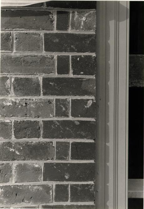 Figure 92
Rubbed brick window jamb. (CWF 84-TCM-1580)
GLAZED BRICK
The decision to use randomly glazed headers and stretchers was based on both the archaeological evidence and contemporary prototypes (Fig. 93). The excavated front pavilion wall revealed an irregular, random pattern of partially glazed headers and stretchers.
Glazed brick was a byproduct of burning clamp with hardwood. Brick stacked in the clamp near the smoke channels were glazed by the potash given off by the chemical reaction of hardwoods as they burned. This glaze generally ranged from a dull greyish-white to a highly glossed green. By the third quarter of the eighteenth century, Flemish bond patterns using a full component of completely glazed headers were an exception rather than the rule. The three brick buildings most contemporary with the hospital, the Bruton Church tower, the Courthouse of 1770, and the William Byrd (Griffin House), all exhibit a random pattern of partially glazed headers and stretchers.
To determine the color, form, texture and pattern of glazing for the hospital, the Church tower and the Courthouse were again used as prototypes. Like the eighteenth-century brick on which it appears, glazes are incredibly varied. Not only is there a wide color variation but also shades of light and dark, textures of gloss and matte and all combinations thereof. There is also an infinite variety of pattern in glazes. A survey of the number of glazed brick at the Bruton Church tower was used
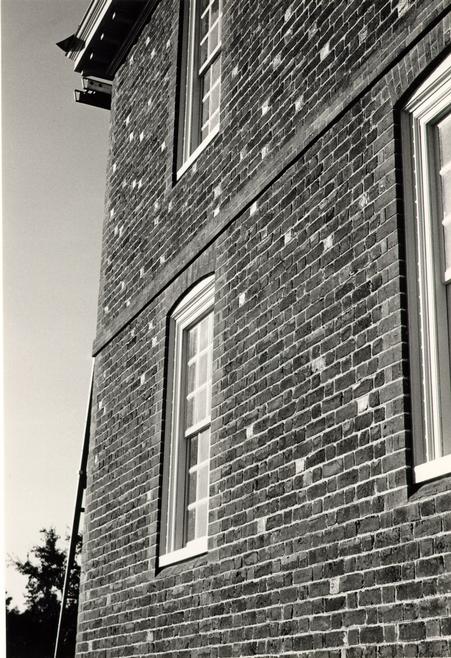 Figure 93
Random pattern of glazed headers on southwest wall of Public Hospital. (CWF 84-TCM 2659 - 20A)
102
for the hospital: 7% headers (full or partial) and 2% stretchers (partial).7
BOND
The only physical evidence for brickwork provided by the hospital itself was, of course, below grade. Predictably, an English bond foundation was confirmed by archaeology. This bonding pattern would have extended above grade to the water table. Above the water table, brick details are unknown due to a lack of artifactual and documentary evidence. Unfortunately, the two historic photographs are not clear enough to provide information for these details. The bond above the water table, according to local and regional tradition, would have been Flemish. Many local examples of this English/Flemish combination exist in Williamsburg: the Public Records Office, the Golden Ball, the Courthouse of 1770, the Wythe House, the President's House, and Brafferton Hall. Excavations also revealed an intact section of American bond wall. Presumably this was the third-story wall, added to the building in 18381840; its bond, bricks, and mortar all reveal the later date.
The mechanics of laying a Flemish bond pattern are as distinctive and idiosyncratic as that of any other building technique. In a Flemish bond pattern, alternating header and stretcher bricks in each horizontal course are laid so that the headers on one row are aligned under and over a stretcher on another course and vice versa. In order to ensure the proper 103 vertical alignment and through-wall bond beginning at a corner or opening, closers are used to begin courses starting with a header. Yet, there is another type of "closer" used for the horizontal "closing" of a course that is a common and essential part of colonial Flemish bond brickwork and one that is nearly always neglected in discussions of the characteristics of such work. The quality of handmade brick produces an unpredictable variety in the horizontal dimension of a wall space, especially when there is a narrow expanse, as between two windows, necessitating one or more brick to make up the horizontal difference in the Flemish bond pattern. This is true in English bond as well. "Make-up bricks" can either be two or more contiguous headers or one or more clipped, shortened stretcher, usually about ¾ of its original size. This is generally referred to by bricklayers as a bat. The actual placement and type of make-up brick varies and it is rare to find a consistent pattern on one building, much less from building to building. In a series of brick panels in a wall, the location of the make-up bricks will be in one or more of three places: on the left near an opening or corner; in the center; or on the right near an opening or corner. Theoretically, if a right-handed bricklayer works from left to right, it is reasonable that the make-ups would occur near the end on the right. In actual practice this is not necessarily the case, because some bricklayers will first lay a dry course which determines the make-up in advance and gives them the option of locating it anywhere in the course. A 104 survey of Williamsburg buildings documented the location of makeups at the Wythe House, 1754; the Palmer House, 1755; Bruton Church tower, 1769; the Courthouse of 1770; and the Norton Cole House, 1809.8 It was found that, with the exception of the Church, all buildings had make-up bricks in more than one consistent location, but the most prevalent placement by far was on the right. The church tower had all of its make-ups on the right, but even these were not consistently placed, as some were located against the rubbed jamb and others one brick away.
In some cases, such as the Bruton Church tower, makeups occur at the first-floor level but not on the same size panel at the second floor level. In other cases, the placement of a make-up immediately next to a rubbed jamb, or one brick away from it, is an attempt to continue a vertical alignment from below a wall opening. Yet, there are just as many or more examples in which the location of make-ups bears no relationship to vertical alignment. Courses which are not interrupted by a masonry opening, such as those below or above windows, will frequently have a make-up on the right and in the center.
While inconsistency is the rule, buildings exhibit varying degrees of quality in brickwork. One of the best examples in town is Bruton Church. The early body of the church, with its decorative pattern of all glazed headers, has areas where no make-ups are used. Some areas of the tower are also carefully done to avoid make-ups. In these instances there are one or more of three reasons for this: a) the dimensions of the bricks and 105 mortar coincidentally matched that of the horizontal space; b) the vertical mortar joints were squeezed or stretched along the entire course; and c) numerous stretchers and headers were imperceptibly clipped. More care seems to have been taken to avoid make-ups when a full pattern of glazed headers are used. on the other end of the scale is the Courthouse of 1770, featuring perhaps the sloppiest of Flemish bonds. The Wythe House falls between these two in quality.
Early reconstructions largely ignored the existence of make-up brick. In those buildings where they were used, for example the Governors' Palace stable, the type and pattern are mechanically similar and thus not at all realistic.
Designing the reconstructed brickwork to include an authentic pattern of make-up brick was problematic. The evolution of decisions on this matter went from ¾" scale drawings showing the exact placement of each make-up brick to drawings showing the general location and, finally, the directive that the placement of make-ups would be determined in the field. This last solution allowed both flexibility and control as the brickwork proceeded. Earley Thompson, foreman of Snow, Jr. and King, masonry contractors for the hospital and gallery, was shown various examples of Flemish bond brickwork in the Historic Area and given a number of options concerning make-up brick. The masons were encouraged to use a variety of solutions and to be less precise in the overall quality of bonding (Figs. 94-95).
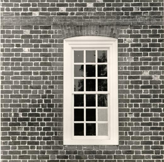 Figure 94
Make=up bricks around first floor window. (CWF 85-FD-406, ls).
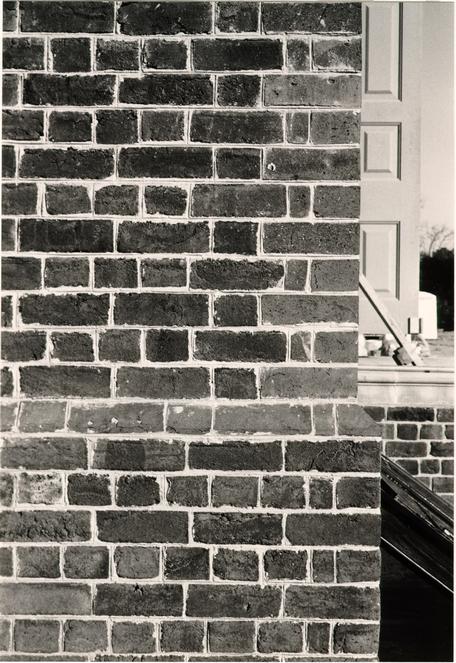 Figure 95
Make-up bricks on west wall of south pavilion. (CWF 85-FD-406, ls)
A rather obscure aspect of bonding, yet one of importance nonetheless, was focused upon at the intersecting corners of the principal walls and the pavilions. An examination of the Courthouse and Bruton Church revealed that the brick course intersections of Flemish bond alternate with either stretchers or headers extending into the adjoining wall. The Courthouse example, with headers on each side extending into the adjoining wall, became the prototype for the hospital. Each passing brick at such intersections has a relatively thin mortar joint on the adjoining wall.9
A survey of original brickwork in the Historic Area was conducted to determine the average size of horizontal and vertical mortar joints. The dimension was found to be 3/8". Four courses were specified to equal 13 ½".10
Unweathered mortar surfaces at Bruton Church tower, the Courthouse, Repiton Office, and the Palmer House exhibit a joint that is recessed from the face and edge of the brick and struck with a smooth, consistently deep line.11 Great attention was given to achieving precisely this appearance in jointing.
CONSTRUCTION
During the design stage a question regarding the thermal expansion of the 4" brick veneer led to an important change. A representative from the Brick Institute of America, upon reviewing the hospital design, predicted a 3/8" thermal crack on both the north and south elevations, and he recommended 107 the inclusion of an expansion joint at the pavilions. The Committee rejected completely any sort of expansion joint and opted instead to increase the thermal mass of the wall by an additional 5" for a total of 9", the length of one brick. The additional advantage of this alteration was a better wall bond with fully locking headers (Fig. 96).
As set forth in the specifications, an approved sample panel constructed by the masonry contractor served as the quality standard for the job. This panel, the second by Snow, Jr. and King, is described in the materials section. One part of the panel, the gauged jack arch mortar joints, was actually better than what had been specified (Figs. 97-98). An examination of gauged work in the Historic Area confirmed that a 1/16" width was more accurate than the 3/32" which was originally specified.
The initial reconstruction brickwork elicited several principal concerns. First, the quality of bonding was too perfect. The bricklayers were striving more for a perfect vertical alignment of headers over and under stretchers than for a consistent mortar joint size. Original examples demonstrated that the alignment varied considerably. Secondly, the quality of the struck mortar joint varied. This was largely the result of timing. Mortar has to have time to set up before it is struck, but time then becomes crucial because the depth and smoothness of the joint decreases as the moisture evaporates (Figs. 99-100). Eighteenth-century mortar joints tend to be buttery smooth, a quality which is undoubtedly aided by the characteristics of
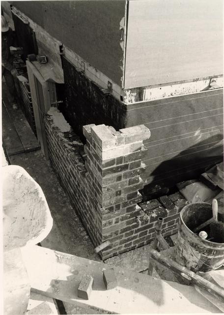 Figure 96
Construction of wall showing thickness and bond. (CWF 84-TCM-1030s).
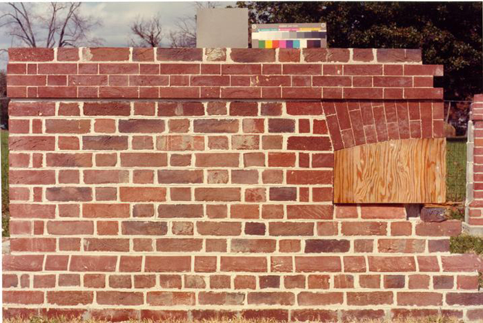 Figure 97
Second trial panel by Snow, Jr. and King using old Carolina brick and "Atlas White" mortar. (CWF K82-FD-841)
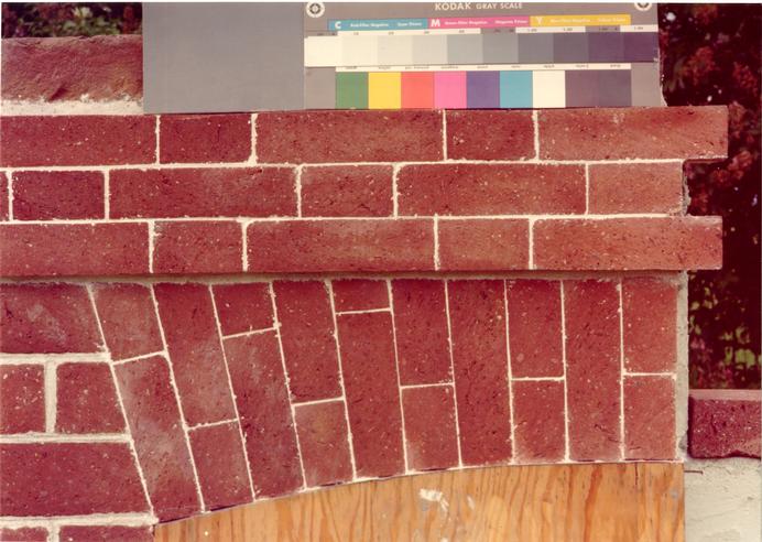 Figure 98
First trial panel by Snow, Jr. and King using Old Carolina brick. (CWF K82-FD-756)
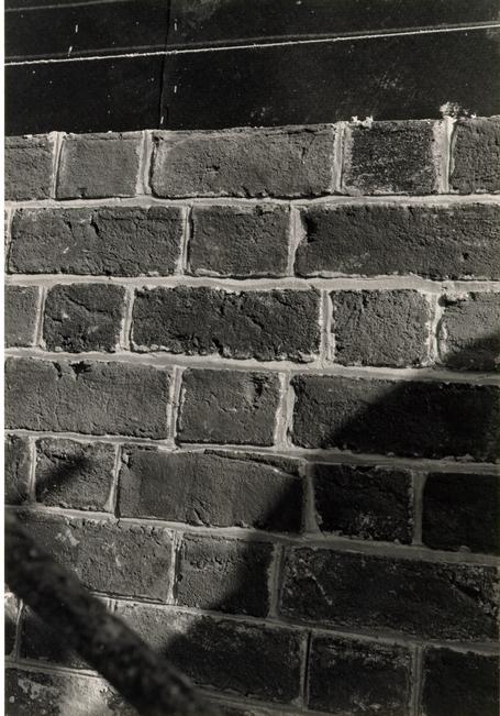 Figure 99
Horizontal joints shown after the mortar is cut from the edges and before being struck with a straight line. (CWF 84-TCM-1592s)
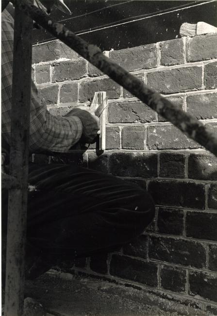 Figure 100
Earley Thompson striking joints with a tool custom-made by CWF blacksmiths. (CWF 84-TCM-1591s)
108
oyster shell mortar with its high proportion of natural lime to sand. The addition of Portland Cement to modern mortar mixes hastens the set up time and consequently reduces the strike time.
Placement of brick was another problem (Fig. 101). The increased wall thickness meant that one-third of the brick would be lost to view as backup stretchers. This presented a problem only because some of the hard-to-achieve brick colors, the plums and dark reds, were being hidden, thus throwing off the desired percentage of exposed colors. In contrast to their usual experience with modern brick, the bricklayers had to make conscious decisions regarding backup bricks.
This conscious decision-making was also applied to the glazed brick. To approximate the percentage of glazed headers and stretchers in the wall, glazed brick, which were on separate pallets, were added to the wall at intervals. The tendency was to place glazed brick at regular intervals. Vigilant coaching helped the bricklayers achieve a more random placement of glazed brick, at times clumping them together and at other times avoiding their use.
Three original hospital bricks were reused in the reconstruction. Two of these are bats which occur just above the water table on the northwest corner of the facade. The third brick was used in a traditional way as a signature brick with "ET 84" carved into it for Earley Thompson and the completion date of the brickwork; this brick was placed near the top of the north pavilion's east wall (Fig. 102).
 Figure 101
Mason placing batts in the back part of the wall. Note square-butt shingle mock-up on roof. (CWF 84-TCM-1652s)
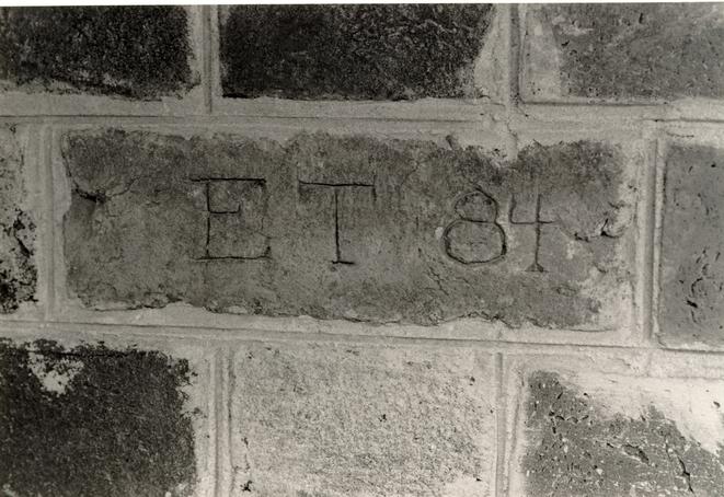 Figure 102
Date brick with initials of head mason Earley Thompson and the brickwork completion date. (CWF 84-TCM-2311, 25).
The following photographs help round out the sequence and documentation of the general brickwork construction (Figs. 103-112). Consult the designated chapters for specific information about the water table, belt course, arches and chimneys.
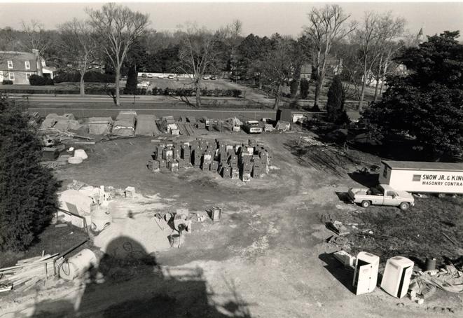 Figure 103
North yard of the Public Hospital site showing mortar preparation area on left, brick storage area in center and experimental brick area in the upper right. (CWF 84-TCM-1056)
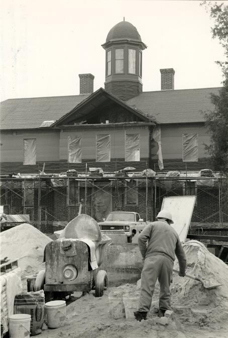 Figure 104
Herbert Moore mixes Fisher sand for the Public Hospital mortar. (CWF 84-TCM-1073)
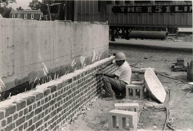 Figure 105
Earley Thompson lays English bond foundation. (CWF 83-5297s TCM)
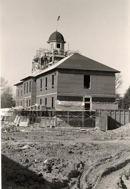 Figure 106
the brickwork was laid around the building to a certain height before the scaffolding was raised to the next level. (CWF 84-TCM-1044s)
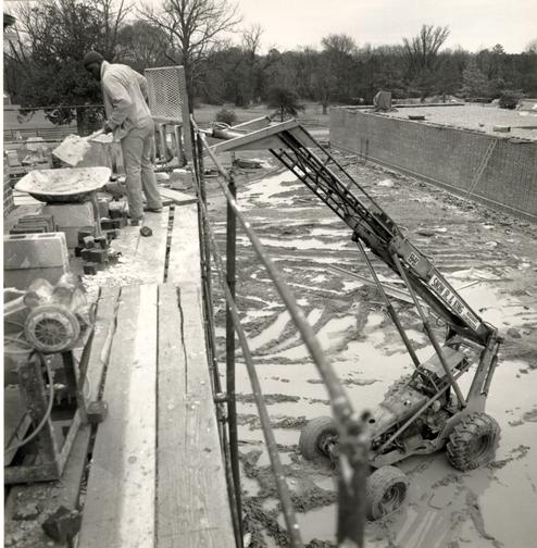 Figure 107
As each new batch of mortar was mixed, the forklift would lift it up to the scaffolding, where it would be constantly mixed with a shovel. (CWF 84-FD-1720-2s)
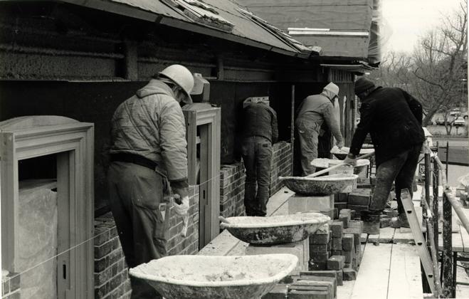 Figure 108
A typical arrangement with each mason having his own pile of bricks and his own tray of mortar. (CWF 84-TCM-1651s).
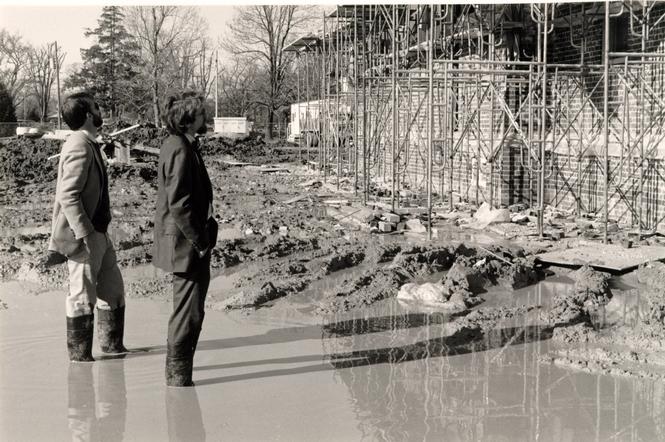 Figure 109
Travis C. McDonald and Edward A. Chappell supervised the site despite the difficulties of rain and mud. (CWF 84-WJG-1496s)
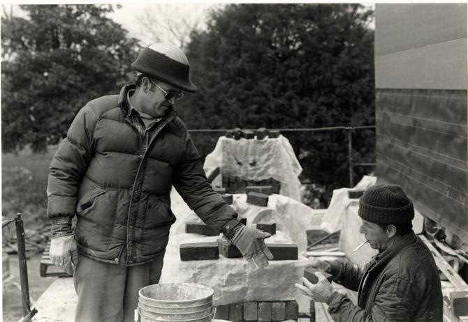 Figure 110
Masonry foreman Earley Thompson (left) and Melvin Haynes (right) carefully recut gauged brick on the scaffolding for tight arches. (CWF 84-TCM 1069s)
 Figure 111
Public Hospital masons, left to right standing: Gary Hughes, Frank Crawley, Earley Thompson and Walter Ford (Melvin Haynes absent). Kneeling are laborers Alton Bell (left and Herbert Moore. (CWF 84-TCM-1691s)
 Figure 112
The entire Snow, Jr. and King masonry crew for the Public Hospital and Wallace Gallery. (CWF 84-TCM-2564-10)
CHAPTER XI
NOTES
CHAPTER XII
CELLAR VENTS
DESCRIPTION
The cellar vent openings at the Public hospital are one header wide and 5 courses high or 4 ¼" x 1' x 5 ¼". The vents are centered between grade and the water table and are aligned under the wing windows of the north and south elevations.
DOCUMENTATION
The Galt drawing mysteriously depicts full cellar windows, but archaeology revealed that only the central pavilion had been excavated as a cellar. Below the wings was unexcavated crawl space.
The inclusion of cellar vents as part of the reconstruction design of the Public Hospital is conjectural, based on substantial local precedent.
PROTOTYPES
Cellar vent openings are associated with unexcavated cellar crawl spaces. Their purpose is to ventilate the dark, low, damp areas under buildings. The size and placement of the openings varies greatly, following no apparent standard. Examples found in Williamsburg and those mentioned in Herbert Claiborne's book Comments on Virginia Brickwork Before 1800, range in size from 2" - 5" in width and from three to five 112 courses high. The President's House at the College, the Powell-Waller House and Carter's Grove have vents that are five courses high.
DESIGN
In the absence of other documentation, the Design Review Committee decided that this element was warranted based on local traditions and precedents. The President's House and Carter's Grove served as the prototypes.
CONSTRUCTION
Modern use of the reconstructed hospital's basement precluded active vents, just as the veneer wall precluded an historic opening thickness. Each of the twelve openings is backed by plywood and painted black (Fig. 113). We regret that the vents were not greater in depth.
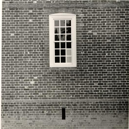 Figure 113
Ventilation opening in the foundation wall. (CWF 85-FD-406, 3s)
CHAPTER XIII
BULKHEAD
DESCRIPTION
The Public Hospital bulkhead is a wooden shed-type cover to the west of the south stairs. Rising to one course below the water table, the bivalve structure is functional only in the sense that it covers a sealed space. It is located on the site of the original cellar entrance.
DOCUMENTATION
Neither Robert Smith's specifications nor Benjamin Powell's contract refers to the exterior cellar entrance or to its cover. The first reference to a cellar door appears in an 1786 work ledger of Humphrey Harwood:
1 This reference is accompanied by another for cutting out three window frames, possibly a reference to cellar windows. This reference may or may not indicate an exterior door. If not for the denial by archaeological evidence, the exterior cellar door and the three cellar windows in the pavilion might be thought to have been cut in at this time. However, archaeological evidence indicates that the bulkhead opening in the foundation wall was not an afterthought, but a feature contemporary with the original construction. Harwood's ledger fails to mention the construction of a cap or cover, which surely would have been needed for a bulkhead entrance.
Archaeology
An archaeological report of December 5, 1980 described the excavated bulkhead:
The bulkhead in the south wall of this building is completely uncovered now, and is seen to have been 4'6" wide between 1 - ½ brick cheek walls. The opening in the south wall at the bottom of the bulkhead was about 4'-0" wide. The sockets for several of the wood step nosing are still in place.2The report included a drawing by James F. Waite. Only the bulkhead's location and size of opening, both established by archaeology, had a bearing on the reconstructed bulkhead design. The archaeological information regarding the steps was not used, as the cellar of the reconstructed hospital is devoted to modern purposes and is at a far different grade.
PROTOTYPES
The most prevalent type of bulkhead in Williamsburg is the low, shed type with wooden bivalve doors. This type by far outnumbers the alternate type: the upright bulkhead ("doghouse" variety) with a gable or lean-to roof. No original bulkhead caps of either type are known to exist in Williamsburg today. In some cases, reconstructed caps were based on either deteriorated fabric or ghost marks at the time of restoration. According to architectural reports, many of the reconstructed shed type bulkhead caps in Williamsburg were modelled on what was believed to be an original example found at the George Reid House.3 Prerestoration photographs and drawings unfortunately do not show this feature, which was rebuilt. In the case of upright bulkhead 115 reconstructions, a memorandum of June 18, 1981 reveals that ghost marks were used to aid the reconstruction of bulkheads at the Palmer House and at the President's House, while surviving caps aided reconstructions at the Robert Carter, Wythe and Taliaferro-Cole houses.4
Bulkheads of the shed type are similar in form but vary in size. This type generally forms a 45 to 60 degree angle where the head attached to the wall. On brick buildings, the head is generally attached to the wall within one course above or, most often, below the water table. The average height at the wall is approximately three feet. The bulkheads are constructed with brick cheek walls on which the wooden bivalve batten doors sit. The foot of the superstructure is also brick and generally from one to three courses in height. The fact of a bulkhead averages about 7' 2" for its length, 6' 6" in door width and from 5" to 8" for the width of side jambs.5
DESIGN
Due to the modern use of the Public Hospital cellar, the bulkhead entrance and its cap are not functional. However, it is designed to have fully functioning doors.
The location of the bulkhead and its dimensions below grade had been determined by archaeological excavations in December 1980. The decision to reconstruct a low, sloping shed type of bulkhead cap as opposed to the upright type was based on the apparently higher incidence of the low type in Williamsburg.6
116Based on archaeological evidence, the bulkhead's outside dimensions were established: 4' 1" from wall to foot and 6' 11 ½" wide. The George Reid House bulkhead was used as a temporary prototype until the committee approved a drawing by James Waite. The Courthouse of 1770 bulkhead provided a modern example of flashing.
Use of the bulkhead as a handicapped entrance into the hospital and gallery was an early possibility ultimately rejected as being too costly.
Because of the juxtaposition of the bulkhead and the south stairs, an awkward 5" space was created between them, posing a maintenance problem.7 A reduction of the south stairs platform did not sufficiently increase the space and created an adequate platform size. The committee then considered combining the bulkhead and stairs by a common brick wall (Fig. 114). This decision to combine the walls was eventually approved and was based on archaeological indications found at the Taliaferro-Cole Shop, the John Carter Store, the Geddy Shop, and Holt's Storehouse.
A later alteration involved raising the height of the bulkhead to one course below the water table in order to increase its slope (Fig. 115).
The bargeboard design was based on examples from the Agricultural Buildings Project (Fig. 116). The random-width boards and nailing pattern were derived from the common pattern
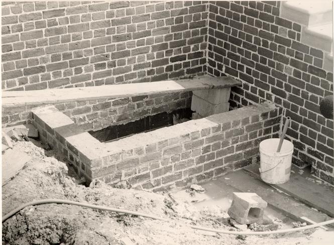 Figure 114
Bulkhead foundation wall. (CWF 84-TCM-2565-15A)
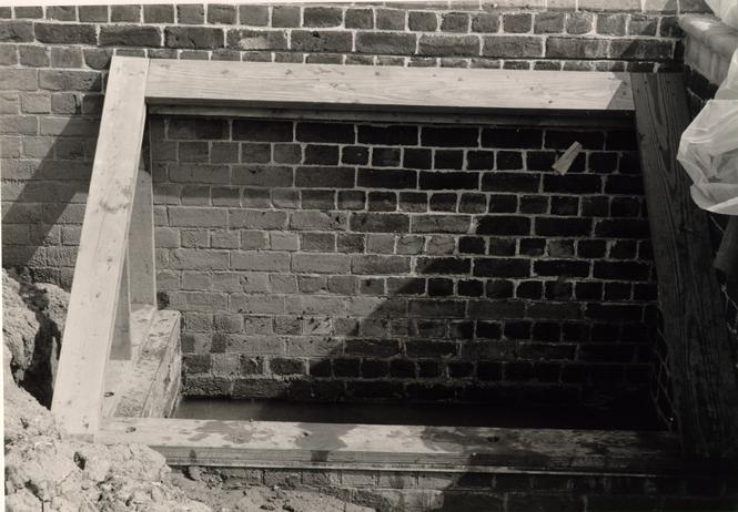 Figure 115
Bulkhead construction (CWF 84-TCM-2240-19s)
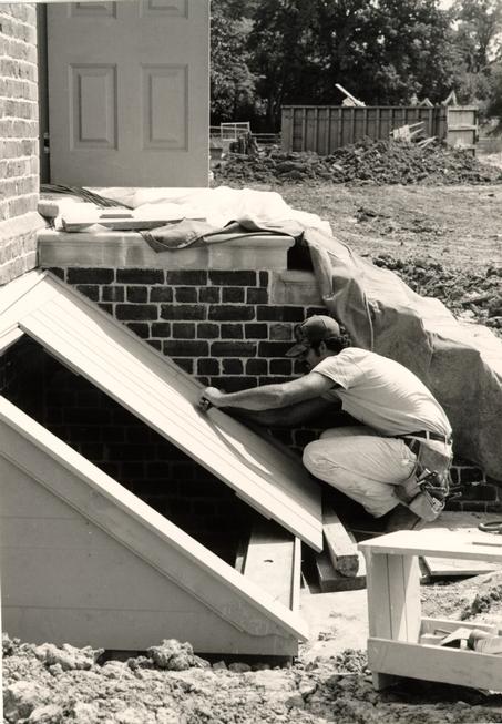 Figure 116
Construction of bulkhead. (CWF 84-TCM-2240-25s)
117
of those features on board-and-batten doors, including those recorded by the Agricultural Buildings Project (Fig. 117).
CONSTRUCTION
From the beginning of its construction, the bulkhead chamber was plagued with standing water. Due to its location over the hospital/gallery tunnel and low position relative to the surrounding grade, the chamber filled with water after a rain. The contractor was slow to remedy this, thus the bulkhead doors warped and mildewed. Eventually, a drainpipe was installed to the southwest leading towards a storm drain. Still, this did not prevent excessive moisture from collecting in the chamber and the space was then filled with concrete. Further changes were made in 1986 to provide sufficient air circulation.
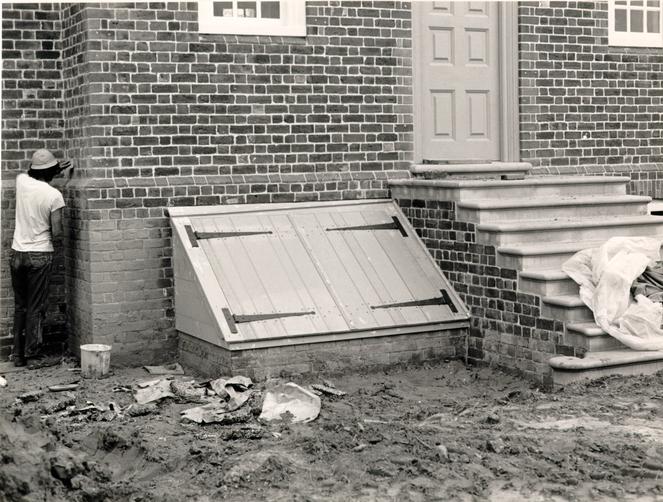 Figure 117
Completed bulkhead. (CWF 84-TCM-2608-10)
CHAPTER XIII
NOTES
CHAPTER XIV
WATER TABLE
The Public Hospital's water table encircles the building in a Flemish bond pattern, dividing the foundation or cellar level from the first floor level. It consists of molded and "rubbed" bevelled bricks 4 ¼" x 3" x 9 ¼" with a ¼" fillet and a 45 degree sloping face.
DOCUMENTATION
Robert Smith
Robert Smith's "Description" mentioned the water table in this way: "After the Wall is worked up as high as the first floor to the full Demensions of the plan set off about 4 Inches which may be of Moulding Bricks."1 A small sketch of the intended water table had been included in the "Description" and was copied along with that document into the Directors' Minutes Book (Fig. 118). Smith also provided information pertaining to the location of the water table above grade: "The Cells shoud be about eight feet high between the under side of the joices and the Surface of the Celler floor." (. . .) "The first floor is designed 3 feet above the Surface of the Ground which will require the Wall about 2 feet or a little more raised above the said Surface."2
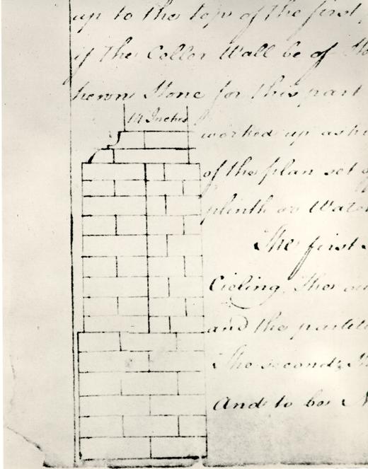 Figure 118
Sketch of a water table after a Robert Smith drawing copied in the Directors' Minute Book. (CWF 81-2769)
Archaeology
During the excavations of the hospital site in 19721973, three bevelled water table bricks were found. These bricks were examined in the archeological lab and discussed with Ivor Noël Hume and Audrey Noël Hume. Audrey Noel Hume then wrote a memorandum dated September 3, 1981, documenting the locations where each brick was found:
I have now checked on records for information on the three water table bricks found in 1972-3 at the Public Hospital site:
3
- 1) E. R. 1713B-4.C was found in a deposit of sand, brick bats and charred wood in the southern half of the central celler in the hospital building and is associated with the latter's destruction.
- 2) E. R. 1770F-4.C was found in a post hole with no datable artifacts.
- 3) E. R. 1769K-4.C was found in a well along with a good deal of building debris which appears to pre-date the 1885 fire. The abandonment of the well may have taken place with the installation of a new water supply system in the 1860s.
The committee examined the bricks on September 11. The brick labelled E.R. 1770F-4.C had been found in a posthole and had been cut rather than molded into a bevelled shape, seemingly eliminating it as an original brick. The brick labelled E.R.1713B-4.C had been found in the central section of the hospital, but was of a red color unlike that found in the foundation's brick color range. The third brick, E.R. 1769K-4.C, had been found in a well with building debris and was of a color that matched some of the original hospital brick. Although this 121 last brick was considered to conform to the rubbed brick color used at the hospital, neither it nor the other two were of a correct size or in a location that would provide conclusive evidence linking them to the original hospital.
On June 11, 1981, it was reported to the committee that archaeology had established the historic grades of the hospital as 84.30' on the north and 83.15' on the south. Excavations had also located the cellar floor. These facts were important in analyzing the specifications given by Robert Smith.
Photographic Evidence
Based on the proportioned photographs, the cellar ceiling was determined to be lower than that given in Robert Smith's specifications, 7' 6" as opposed to Smith's 8'.
PROTOTYPES
The typical water table of eighteenth-century Williamsburg was a simple, molded, bevelled brick course projecting from the wall about 2". Examples of this type of water table appear at the Palmer House, Public Records Office, Greenhow-Repiton Office, Wythe House, President's House, Brafferton Hall, Courthouse of 1770, and Bruton Church.
Local buildings most contemporary with the Public Hospital exhibit a rubbed water table brick that is a dark red color: the Courthouse of 1770, the Bruton Church tower, and the 122 Griffin House.4 On the Church tower and the Courthouse, this color is within the general range of field brick.
In a comparison of water table heights in Williamsburg, a measurement was made from grade to the course below the bevelled water table brick: Brafferton, 2' 9"; Wren Building, 4' 10"; President's House, 3' 11"; Courthouse of 1770, 2' 11"; Public Records Office 3' 5"; Gaol, 3' 6"; Wythe House, 3' 7". In a similar comparative study by James Waite using local Williamsburg examples, it was found that the average water table height was 3' 6".
Virginia
Using Herbert Claiborne's study, Comments on Virginia brickwork Before 1800 (1957), a survey of water table heights was made with a general range and average approximating that of Williamsburg examples: Charles City Courthouse, 2' 7"; Christ Church, Lancaster, 3' 6"; Matapony Church 2' 7"; Colonial Church, King an County, 1' 8"; St. John's Church, King William County, 1" 8"; St. Peter's Church, New Kent County, 5'; Brandon, 3' 3"; Monticello, 3' 4"; and the Shields House, Yorktown, 4' 5".
Robert Smith
The water table suggested by Robert Smith was a two-part brick design common to public brick buildings in Philadelphia, such as the buildings comprising the Independence Hall group, the Pennsylvania Hospital, Carpenter's Hall, Christ 123 Church, and St. Peter's Church. It was logical that Smith proposed a detail common to his own work and that around him in Philadelphia.
DESIGN
Even though Robert Smith specified a comparatively elaborate, two part water table, the committee felt that, actually, a simple bevelled water table had been executed. Evidence of a consistent, characteristic local detail formed the basis for this decision. Local Virginia craftsmen used the same details over and over again, just as Philadelphia craftsmen consistently produced the type of detail specified by Smith.
Due to the inconclusive evidence provided by the three bevelled bricks uncovered in archaeological excavations, the committee decided that the color of the water table bricks, and that of other rubbed dressings, would be based on that of contemporary prototypes. The dark red dressings of the Bruton Church tower, in particular, and the rubbed window dressings at the Courthouse of 1770 served as the color prototype. This color is one found within the range of examined hospital foundation bricks.
The establishment of historic grade by archaeology brought to light a discrepancy in Smith's specifications. Based on the historic grade and the archaeological level of the cellar floor, Smith's 3' water table height and his 8' basement height do not coincide. Using the historic grade and a proportional 124 analysis of the historic photographs, James Waite calculated that the original cellar height would have been about 7' 6". After reexamining historic photographs, archaeological evidence, and water table comparisons, the committee established the water table at 3' 6" on the north elevation. This corresponded with the height of the water table seen in the south elevation photograph and with the height of the porch in the north elevation photograph. Although it is an academic question considering the present use of the building, the corresponding original cellar height was then determined to be 6' 6". This low cellar was not without precedent, some cellars being about 6' in height.5 Architects Roche/Dinkeloo requested a change in grade, which was finally established at a non-historic level of 85.44 for the north and 84.29 for the south, still retaining the historic north-south proportional difference. This adjustment established the water table at 88.80 on the north or a height of 3' 4 ½".
Construction of a sample brick panel proved crucial for the design of the water table, as well as for many other elements. Changes brought about by the mock-up included reducing the fillet from 7/8" to 5/8";6 reducing the vertical mortar joints between water table bricks from 3/8" to 1/4";7 having sharp, "rubbed" sides;8 and using an alternating bond for the corner brick just above the water table corner.9
CHAPTER XIV
NOTES
CHAPTER XV
CELLAR WINDOWS
DESCRIPTION
The Public hospital's cellar windows are located in the central pavilion: two flank the door on the north and one is positioned east of the door on the south. Each window is composed of a wooden grille of horizontal bars set into a central vertical post. A batten shutter closes the opening. Above each window is a rubbed and gauged brick jack arch similar to those of the first and second floor windows (Fig. 119).
DOCUMENTATION
There is no written documentation that specifically refers to the use of the cellar at the Public Hospital. Evidence indicates, however, that at least part of it was used as a kitchen. In June of 1776, Humphrey Harwood billed the hospital directors for three days labor in laying 1000 bricks for "kitching floors & layg. harth & mendg. back."1
Another account by Harwood in October of that same year cited the use of 400 bricks in "mending a kitching chimney."2
In August of 1778, the Directors "ordered that the keeper of the hospital employ a person to build an oven."3
There is no evidence to indicate that a separate exterior kitchen existed during these years. The Galt cottage to the south of the hospital might have served as a kitchen until the detached kitchen that appears on the 1821
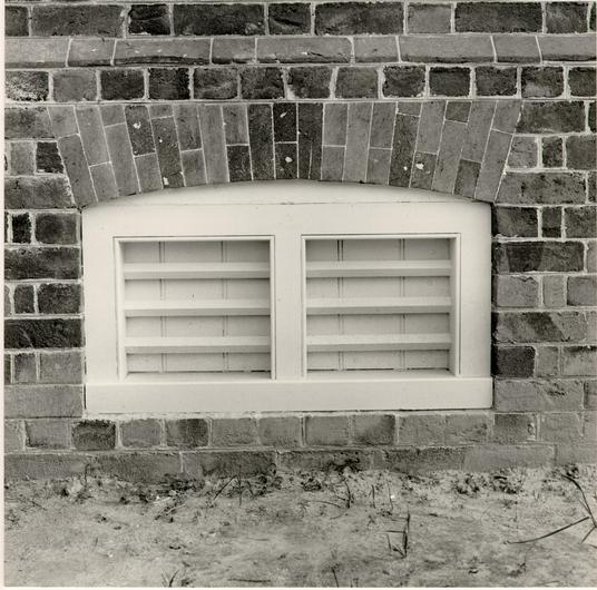 Figure 119
Bevelled brick water table and shuttered cellar window. (CWF 85-FD-406, 5s)
127
insurance plat was constructed. It is likely, however, that the original kitchen occupied the cellar of the hospital until the construction of a detached building. Thomas Condie's 1798 description of Robert Smith's Walnut Street Jail in Philadelphia mentions that the kitchen was in the cellar of that building.4 A reference in September 1786 to "cutting out Cellar door frame & working in one"5 and "To do. three window frames"6 might possibly refer to the cellar windows, if not to some other outbuilding. It is possible that either the cellar windows were added at this time or that the openings were changed from grilled shutters to glazed casements. Additional cellar cells constructed in 17997 probably required their own windows. An 1803 work order for "8 cellar window frames"8 indicates that the new cells might not have had windows for four years. It is also possible, yet unlikely, that this unexplained number of eight windows might account for the six cellar wing windows seen in the Galt drawing. Five of these would have functioned solely for ventilating a crawl space. An 1815 reference to "cellar window shutters"9 and one in 1828 to "four cellar window frames w/o bars and two with bars"10 indicate that cellar windows, at least at a later date if not during the early period, had bars and shutters, probably in combination. There is also a reference to "wooden grates and shutters" for the hospital buildings of 1820 and 1824.
Archaeology
Archaeology revealed no information about the cellar windows because the hospital walls had been dismantled below the window level. Excavations did confirm that the brick floor of the central cellar space was not original, perhaps indicating the work by Harwood in 1776 and 1778 and the use of that space as the kitchen. The archaeological evidence was interpreted as follows;
At the time of the excavation brick flooring existed in the entire center basement space, except where it was disturbed by the steam tunnel and where it had been robbed. The color and small size of the bricks indicated that it was not an original floor, although there may have been a brick floor earlier, perhaps taken up and relaid due to dampness which plagued the Hospital from the beginning. There are indications that no brick flooring existed in the original basement.11More revealing was the evidence of a large fireplace, including scorching and a crane hook that could have been used for cooking.
As already noted, archaeology established the fact that the original cellar area was confined to the pavilion. This information influenced the decision to design only three cellar windows. The bulkhead location, also established by archaeology, occupied the area west of the south door where a corresponding window would have been. Based on archaeological evidence and written documentation, the full cellar treatment suggested by the "Galt" drawing was considered inaccurate.
PROTOTYPES
Grilled cellar windows were a common feature of eighteenth-century buildings. In his book, Eighteenth Century Houses of Williamsburg, Marcus Whiffen remarks that cellar windows were "unglazed …closed with grilles of close-set bars, usually horizontal and usually of wood, occasionally of iron."12 The number of bars varied, depending on the size of the window, but typically a grille had three or four horizontal wooden bars often set into a center post or mullion. The Prentis Store had just such an arrangement: "Grilles with four square, horizontal wood bars placed diagonally in beaded, unmolded frames divided by a central mullion, were originally installed in front of both of these windows… ."13 The Greenhow-Repiton Brick office also included a similar construction, although its original bars of iron were later replaced by ones of wood.14 Surviving Williamsburg houses with the same arrangement of wooden cellar grilles include: the Orrell House, the Bracken House, the Tayloe House, the Wythe House, and the President's House. All have a beaded frame with horizontal bars, usually of wood. Generally, cellar grilles were finished with a simple bead and only occasionally with a more elaborate cyma reversa molding. The combination of a glazed window and a grilled frame in a cellar is rare. Examples include Scotchtown in Hanover County, Rosegill in Middlesex County, Shirley in Charles City County, and Blandfield in Essex County. Only one Williamsburg example is 130 known to have had a sash rebate in combination with a grilled opening. The Wythe House cellar windows had an interior sash rebate and the remains of leather hinges for a top-hung, inward-swinging sash or, more likely, a solid batten shutter.
DESIGN
The size of the cellar windows was based on photographic evidence, as well as local prototypes. The historic photograph of the south elevation established that the cellar windows, albeit of a later period, were aligned under the first floor windows and appeared to be of the same width. This was a common arrangement. James F. Waite's dimension for the upper windows, 3' 4", was thus adopted for the cellar openings. The height, 1' 8" - 1' 11", was established according to prototypes at the Palmer House and the President's House.
The question of whether unexcavated cellar spaces would have been ventilated by full grilled windows, as seen in the Galt drawing, or just ventilator slots was answered by a lack of evidence for the former situation.
A lack of evidence for both glazed and grilled cellar openings led the committee to decide on a grilled cellar opening backed by a batten shutter. The fact that a shutter allowed the entry of either light or air but not both reflects on the low priority of the domestic kitchen staff.
CONSTRUCTION
The shutters were made of ship-lapped boards with nails placed according to a pattern observed in historic batten construction. They are non-functional due to the modern use of the reconstructed building's cellar.
CHAPTER XV
NOTES
CHAPTER XVI
STAIRS
DESCRIPTION
The Public Hospital has two stairs of stone and two of wood. The north and south stairs are constructed of cut limestone slabs resting on brick foundations. The north stairs are composed of five 12" treads, six 6 3/4" risers, a 4' x 8' platform and wrought iron handrail (Figs. 120 - 121). The south stairs are composed of eight 12" treads, seven 6 3/4" risers, a 4' x 6' platform and a wrought iron handrail (Fig. 122). The east and west stairs, porch and balustrade are constructed of wood, supported on brick piers. The east and west stairs are composed of seven 12" treads, six 6 ¾" risers and a 4' x 5' 4 ½" platform.
DOCUMENTATION
Among the materials ordered from England for the eighteenth-century hospital were stone steps. Just as the weathervane and iron window grates had been ordered by different directors, William Nelson and Robert Carter respectively, the responsibility of ordering stone steps fell to Robert Carter Nicholas. Nicholas had been asked "to import from England Stone Steps for the use of the hospital."1 which he ordered through John Norton & Sons in London on August 4, 1772:
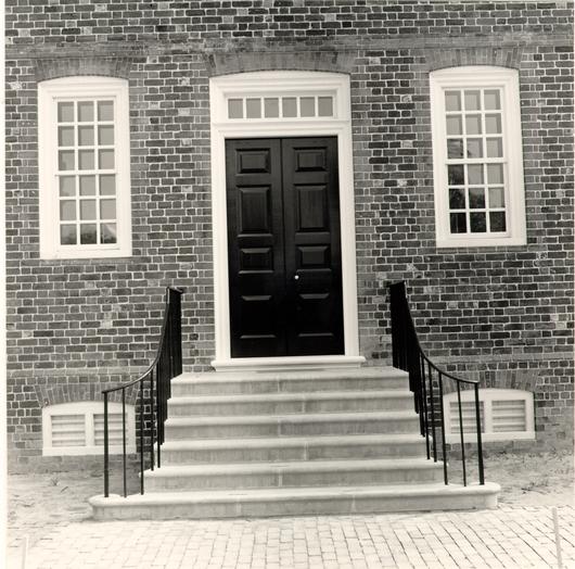 Figure 120
North stairs. (CWF 85-FD-406, 9s)
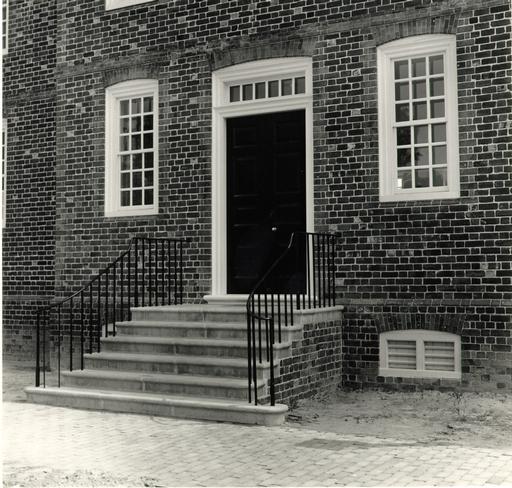 Figure 121
North stairs (similar to south stairs). (CWF 85-FD-406-12)
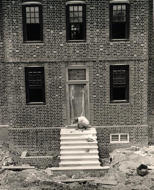 Figure 122
Frank Dunham sets wrought iron cramps in south stairs. (CWF 84-TCM 2613-32)
134
I trouble you with a Letter for Mr. Saml. Martin of Whitehaven, it is to desire the favour of him to send over some Stone Steps for an Hospital the Country is building for the Reception of Lunaticks & other unhappy objects of insane Minds, which it is to be fear'd will multiply too fast in this Country; we have been obligued to send four to the Hospital at Philadelphia for want of a proper place to accomodate them here; having but little Acquaintance with Mr. Martin I have desired the favour of him to draw on you for the Amount of the Steps & desire you will give due Honor to h s Draught, & charge the Money to the Treasury… .2The Treasurer's Office records indicate that the stone was paid for on December 14, 1773: To Norton & son for the Hospital Steps £ 5..9..8."3 The same records also indicate that £ 1..19 had been paid for freight.4
An interesting connection between the contemporary hospital and Courthouse is the building accounts for stone steps ordered for each building from England. In their architectural report on the restoration of the Courthouse of 1770, Lawrence Kocher and Howard Dearstyne made the following observation:
No reference was found to supply-detailed information on the building operation but the time of its completion is indicated by a letter of William Nelson to Samuel Martin, July 2, 1722, which expresses thanks for the 'stone steps for the Court House in Williamsburg, which came in good order and was to the entire satisfaction of those concerned in the Building: Mr. Nicholas, I expect, will acknowledge your civility in sending them Freight free… .5The "Mr. Nicholas" referred to was no doubt Robert Carter Nicholas, who, one month after Nelson's letter, wrote for the hospital's stone steps, as already mentioned.
Specific information regarding the order of stone has not been found. It is unknown whether Nicholas specified the type of stone, the amount of stone, or the shape, and whether he 135 specified it by written description or by a drawing. Robert Smith's written specifications failed to mention any exterior stairs or porches. It can only be assumed that these elements were specified through drawings, most likely on the "plan" mentioned in Smith's "Description."
References to exterior stairs or porches are not found in hospital documentation until 1803. In 1803 John Bowden was paid for building porch benches, repairing porch balusters, and applying four iron straps to the porch.6 This reference might possibly refer to an outbuilding, such as the kitchen, but more likely it refers to a second period porch on the north or south. No documentation has been found either to confirm the type of original stairs and porch on the south or to indicate any later construction or rebuilding. The 1803 reference indicates the presence of a porch sufficiently large for benches. It is unlikely that the east and west stair platforms were large enough to hold benches, leaving either the north or south stairs as a possibilities. The reference to "repairs" indicates that the porch was already there and somewhat deteriorated. Archaeological excavations (discussed under ARCHAEOLOGY) determined that the porch posts found at the south pavilion date to the nineteenth century, so the question remains as to whether the 1803 reference was made to a second period porch on the north or south.
An account for Richard Garrett in April 1809 indicates that either an existing porch was being heavily repaired or a new 136 one constructed. This, again, might possibly refer to a second period north or south porch, or perhaps to the Convalescent House.7
In December 1826, James Guthrie billed the hospital for "makeing 42 feet of benches for porch."8 The possible locations for benches at this time are too numerous, due to the construction of two buildings in 1821 and 1825.
The next reference is more specific and occurs in December 1828. At that time the directors authorized that "to the North front of the main building of the Hospital a Portico of the like demensions of the one on the Southside thereof."9 be built. James Guthrie presented his account for this work in January 1829: "To Building front Portoco compleat and finding all the meterials with Brick work."10 This reference would seem to indicate that either the 1803 or 1809 reference did not relate to the north porch, but to the south. This new north porch is probably the one shown in the Galt drawing.
Finally, in 1840, "The directors ordered that the north and south porticoes of Building A- the original building be rebuilt or repaired."11 It is not known whether this order was carried out, since the large Greek Revival portico on the north was constructed in 1844-45.
Archaeology
The first archaeological search for stair evidence was conducted in June 1972, one month after the initial excavation of 137 the hospital had begun. This effort at the south pavilion failed to locate any evidence for the original stairs. What was found south of the central pavilion on the south side were four brick piers associated with a nineteenth-century porch. This is probably either the porch seen in the photograph of the south elevation or its predecessor.
The area north of the central pavilion on the north side was excavated in February 1980 and found to contain a complex evolution of stairs, porches and porticoes (Fig. 123). Almost nothing remained of the original period stairs:
When the excavations of this north pavilion area were thoroughly completed in March 1980, the earlier conclusions were still valid:During the month of February the field crew began excavations at the Public Hospital site with the goal of identifying and assigning a chronology to the many porticoes, porches, and walkways that existed at the north entrance of the 1773 building.
Although excavations in this area are not complete an expansion of it has commenced in a easterly direction. All current evidence points to the survival of porticoes from four construction phases of the north portico area.
Evidence of the Public Hospital's first period entrance comprised a small section of the brickwork, almost obliterated by a utility trench, which appears to have been the bottom course of a step foundation. This step, probably no wider than the north door, appears to be the only extant physical evidence of the original entrance. The fact that part of this feature has been chopped away to accommodate the hole for a brick pier that supported one of the ca. 1824 to ca. 1840 portico pillars (Period III), gives credence to this conclusion.
Flanking pilaster bases, one almost completely destroyed, the other as yet only partially excavated, are the only remains of the second period. These two bases, laid with shell mortar, are probably part of some sort of portico that existed during the first quarter of the 19th century. So far no other evidence of this structure has been located.
138
Figure 123
Archaeology of north steps area. (CWF 81-DS-2715)The Period III portico remains, consisting of two brick pilaster bases and four holes for similar piers to the north, a configuration which seems to parallel the type of portico known to exist at the hospital during the second quarter of the 19th century. To the north of this portico structure was found a circular brick wall, composed of reused brick with buff sandy mortar, sitting atop a drylaid brickbat floor. In an area to the south of the extant brick floor, and flanked on either side by the Period IV trenches, were found brickbat impressions which could indicate that the floor once extended to the front of Period III portico. It is believed that this structure, partially cut by the Period IV foundation trench, is somehow related to the Period III portico, however, the exact correlation in unknown.
The Period IV evidence is made up of two partially excavated trenches, ten feet north of the hospital building, and a 1' 6" wide brick wall. These two elements appear to be the remnants of the massive Greek Revival portico that stood from ca. 1840 until the destructive fire in 1885. The fact that these two features extend east and west of the Hospital's off-set wall indicates that they are related to the much larger portico built in the mid 19th century.
At the north of the excavation area was found a brick rubble walkway that could be part of the Period II entrance, and a post hole complex which seems to be related to the post 1885 administrative building located to the south of the colonial building.12
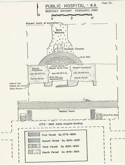
The reference to a Period II north porch and stairs is the only unexplained evidence. The Period III evidence is clearly the porch or "portoco" built by James Guthrie in 1828. The Period IV evidence is likewise well documented as corresponding to the Greek Revival portico constructed in 1844-45. The Period II evidence, however, is a mystery if indeed those remains are not associated with either Period I or III. A possible reference to repairs or new porch construction in 1809 might possibly be the Period II remains, unless it pertains to the Convalescent House.Excavations at the Public Hospital continued to focus on the area of the front porch during the first two weeks of March. It is presently believed that all evidence of the original porch has been obliterated by the construction of three later porches. The earliest remaining foundations are archaeological features related to the second porch, ca. 1800-1825. This is represented by sections of brick foundations abutting the north pavilion wall, suggesting a semi-circular porch 29 feet wide at the base set in shell mortar, the foundation had a top course of rowlock bricks. Interpretation of the period III and IV porches remains unchanged with one additional supposition; the two 139 brick wide wall 4'-4" north of the pavilion is probably associated with the 1845 porch and the widening of the front of the hospital to accommodate the Greek Revival portico.13
Photographic/Pictorial
Both historic photographs record later porches and stairs. The photograph of the north elevation shows the 1844-45 Greek Revival portico, while the photograph of the south shows a two tier porch. The lower part of the south porch might perhaps be that referred to in 1803 or 1809, but, more likely, it represents the 1828 or 1840 references. The stairs seen at the extreme right, or eastern, bay of the hospital in the south elevation photograph are obviously a later nineteenth-century addition.
The Galt drawing shows a porch on the north elevation. This is probably the Period III porch, constructed in 1828, whose remains are mentioned in the Archaeology section. Dickie Galt was paid $100 in 1829 to draw a "plan of the institution."14
PROTOTYPES
Local eighteenth-century stairs served as important prototypes due to the lack of information about the original stairs. Based on a survey of stair forms in the Historic Area, it was determined that two probable designs existed for the original north stairs of the hospital: pyramidal or a straight flight with a curved bottom. The latter seemed most likely, because the former would cut off the basement-windows. Considering the calculated size of the stairs, a stair form with a straight flight and a flared bottom was considered the more appropriate type (see Design Review Committee minutes for a more complete discussion of this subject). Original examples of this type can be found at the President's House, the Semple House and the Palmer House. The front stairs at the Palmer House and the north stairs at the President's House served as prototypes not only because the steps were original but the iron balustrade is considered the only known extant eighteenth-century example in the Historic Area. Details of the brickwork at the sides were influenced by original brickwork surviving below the upriver side step at Tuckahoe in Goochland County.
DESIGN
It was first determined that the documented cost of the stone ordered from England indicated a relatively small amount of material. Based on this assumption, the committee decided on a 141 front (north) stairs of stone and stairs of wood on the south, east and west. The original stairs at the Palmer House were first chosen as a possible prototype for the north stairs. This stair form consisted of a straight flight of steps descending from a platform and ending with a spiral formed by the last two steps. This configuration, combined with the number of risers calculated from the known historic grade and the water table, conformed approximately to the location where Period I remains (discussed under Archaeology) were found.
The Department of Research was unable to find any contemporary orders for stone placed with English suppliers. An analysis was then made of the documented price paid for the Public Hospital stone, contemporary prices of stone obtained from England, exchange rates, and the estimated requisite size of the stairs and porch.15 Prices for English stone in the eighteenth century fluctuated between 0..1..8 and 1..1..4 foot/superficial from the 1730s to the turn-of-the-century. Richard Neve's The City and Country's Purchaser's and Builder's Dictionary, 1736, listed Portland stone at 1 shilling/8 pence per foot superficial. The sixth edition of William Salmon's Palladio Londinensis, 1762, listed Portland at 1 shilling/4 pence per foot superficial. William Pain listed Portland as 1 shilling/6 pence per foot superficial in his The Builders Companion of 1765 and as 4 pence per foot superficial in his Practical House Carpenter of 1790. Before subsequent references were found, Neve's price was used as a variable.
142Harold Gill of the Department of Research suggested that, based on comparable goods, the prices of stone would not have varied greatly in either 1736, when Neve recorded stone prices, or 1772, the year in which the hospital stone was ordered. Calculation was later proven correct when the prices listed in Pain's book of 1765 were determined to be very close to Neve's prices of 1736. Harold Gill was also able to state that the exchange rate between England and Virginia in 1722 was 22.5%. Calculations were then made using the cost paid for the stone, the exchange rate, the price of the stone, the conjectural size of the stairs and the eighteenth century definition (O.E.D.) of "superficial" as square footage in a rectangular size.
Neve's 1 shilling/8 pence converted into 24.5 pence per square foot, including the exchange variable of 22.5%. Considering just the north stairs, the cost of stone indicated a much larger area than had first been imagined. By dividing the cost of the stone, £ 5L.9..8, by the price £ .L24..5, approximately 185.8 square feet of stone could have been purchased. Thus, there were either very large stone stairs on the north and three sets of wooden stairs on the south, east and west, or stone stairs on the south as well as the north and wooden stairs on the east and west. The possibility that some of the cost had been for freight was discounted by the documentation of the freight charge of L 1..19..as a separate expense.16 The use of stone for more than one stairs was found to be the case for a number of Williamsburg buildings: the Lightfoot House, the 143 Semple House, the George Reid House, the Governor's Palace, the Capitol, the President's House, and the Nicholson Shop. In all of these examples the primary stairs differed in form from that of the secondary stairs. These combinations represented three different types of stone stairs found in Williamsburg: a semicircular form with concentric steps; a pyramidal form with steps on three sides; and a straight flight with or without a flared base ending in a spiral. Based on Robert Smith's Walnut Street Jail in Philadelphia, 1773-77, it was recommended to the committee that, pending more precise calculations of the area of stone, a pyramidal form be used for the north and a straight flight with flared base for the south. When the pyramidal form was calculated for the north, it was found to extend across the cellar windows of the pavilion. Even though the pyramidal form had been designed to extend across the cellar windows at the Walnut Street Jail, the majority of the committee felt that the cellar windows should not be removed and or covered in any way. The alternative solution of a straight stairs with a flared base was approved for both the north and south stairs. This solution accounts for the approximate amount of stone as indicated from the purchase cost and calculations.
The Palmer House stairs were the first prototype for the hospital, but were later superseded by the north stairs of the President's House. This change was made when it was determined that the iron balustrade on the north stairs of the President's House was the only documented eighteenth-century 144 survivor of its type in the area. To honor an early policy decision to avoid mixing prototypical parts in the same building element when possible, it was decided to use the President's House as the stair prototype as well. That the stone had already been ordered based on the Palmer House was not realized soon enough; nevertheless the stone arrived at the site and was used.
The depth of the stair platforms was set at 4' while the width was established by the width of the doors. Examples of stone stair platforms in the Historic Area were found to be from 3'-6' deep, with a majority just less than 4'.
The relationship of stone step riser to the brick coursing was established at 1 to 2. This ratio worked out unevenly on the north stairs, with the need for either an additional brick course creating an additional step, or a change in grade. The number of steps was somewhat conjectural due to the changing grades over time so it was decided to increase the steps from five to six. The cheek wall bond was established as English Bond to match that of the foundation.
It was then discovered that the juxtaposition of the bulkhead with the south stairs created an awkward 5" gap between. Because of an anticipated maintenance problem, James Tuley recommended combining the east wall of the bulkhead with the west wall of the stairs. To avoid compromising the correct location of the bulkhead, as determined by archaeology, the committee decided instead to try reducing the width of the stair platform and steps. The narrowest stairs, it was found, only increased 145 the troublesome space by 6"-7". With no further alternatives, the bulkhead and stairs were combined after such a combination was found to have been used historically at the Cole Shop, John Carter's Store and the Geddy Shop.
A mistake in the detail of the stair nosings should be pointed out. When initial drawings were traced in Charlottesville, the corners of most of the treads were rounded. This mistake was not recognized by the committee, and, as a result, most of the corner pieces arrived with softened edges. This should be corrected if there is ever occasion to replace the front and rear stairs. The nosings of the front and sides should intersect sharply. This was achieved by widening the steps.
Original eighteenth-century prototypes could not be found for exterior wooden stairs. The committee felt that, because of their secondary location, the wooden stairs at the hospital would have been fairly simple in design. Based on this assumption, it was first decided to use a simple handrail that had been found during the Agricultural Buildings Project survey of Southampton County. This interior stair railing was from the Catherine Whitehead House kitchen. The committee later changed its decision, feeling that the form and details of the Whitehead kitchen rail were those of an interior element not suitable for an exterior stair. The difference in scale between a small domestic building and a much larger public one was also a concern. The committee then settled on a handrail from the southwest porch of the Coke-Garrett House. The architectural 146 report for that house states that the current rail there was modelled on the original, but deteriorated, eighteenth-century rail replaced during restoration.
There were problems with the quality of workmanship when the east hospital stair was built, and when rebuilt, aspects of a simple early stair in the service wing at Brandon were incorporated into the new design. Due to the intended use of the east yard, the east stairs were originally designed to be different from those on the west, including more authentic framing and one-piece treads. Due to the Brandon prototype an even greater difference is seen in the east stairs: smaller posts, half-caps on the post pilasters, a smaller handrail, larger balusters, larger baluster rails, a proper rail mortise, and tongue-and-groove flooring.17 Already significantly compromised by the handicapped wheelchair ramp, the west stairs were not rebuilt to match the east stairs.
Other features of the wooden porch were kept as simple as possible. The 4' platform depth of the stone stairs was also used for the wooden stairs. The width of the platform corresponds to that of the doors.
MATERIAL
Portland stone from England was the original material of the principal steps. The Design Review Committee, however, chose Indiana limestone because it had been used as a substitute for Portland stone since World War II when the latter could not 147 be obtained. The limestone sample that most closely matched Portland Stone examples in the Historic Area was a "Standard, hard grade gray" with a smooth planar finish. The Fluck Stone Company of Bloomington, Indiana made the steps.
Iron railings and cramps were made by CWF blacksmiths at the Deane Forge.
CONSTRUCTION
Early Thompson, supervisor for the masonry subcontractor Snow, Jr. and King, constructed the north and south stairs; the cramps were leaded by Frank Dunman of that same firm (Figs. 124-135). Whereas the cramps are set entirely within lead, the iron handrails were first set in a masonry grout and then leaded.
 Figure 124
Unassembled Indiana limestone steps at Hospital site. (CWF 84-EAC-2458-2)
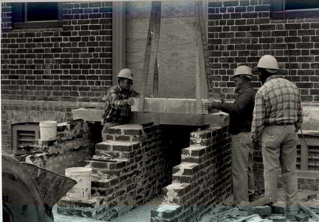 Figure 125
Stone steps are lifted into place. Left to right Early Thompson, Bill Brinkley and Herbert Moore. (CWF 84-TCM-2311-50-26, 10A)
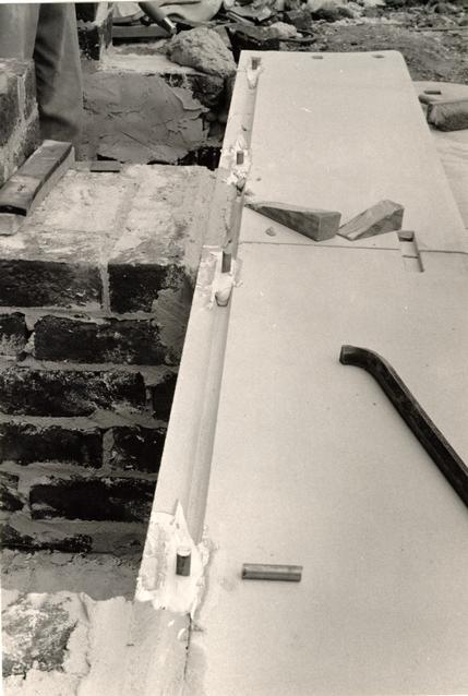 Figure 126
Steel dowels set in grout to interlock steps. (CWF 84-TCM-2310s 26A32, 31
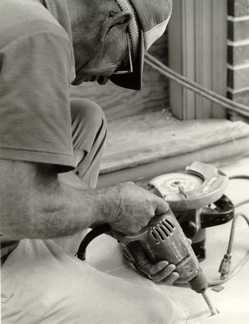 Figure 127
Frank Dunman preparing steps for cramps. (CWF 84-TCM-2610-13)
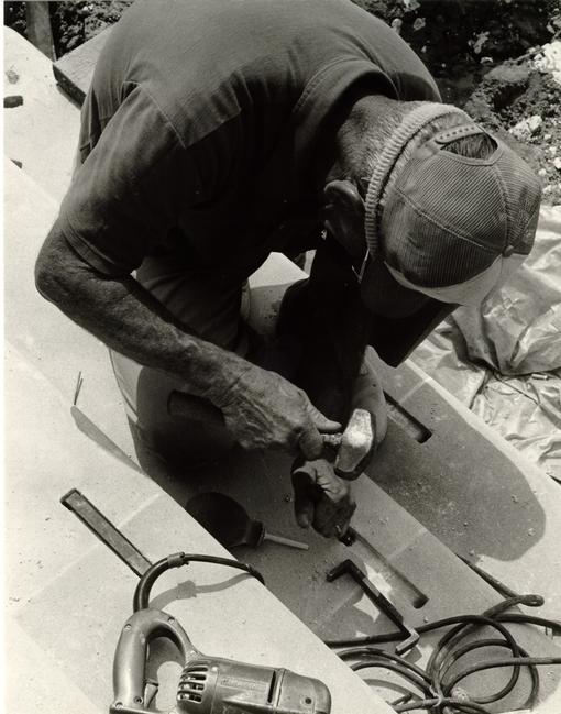 Figure 128
Frank Dunman preparing steps for cramps. (CWF 84-TCM-2610-3)
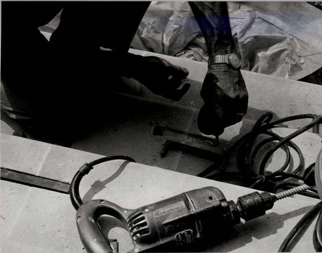 Figure 129
Cramp hole is blown free of debris. (CWF 84-TCM-2610-5)
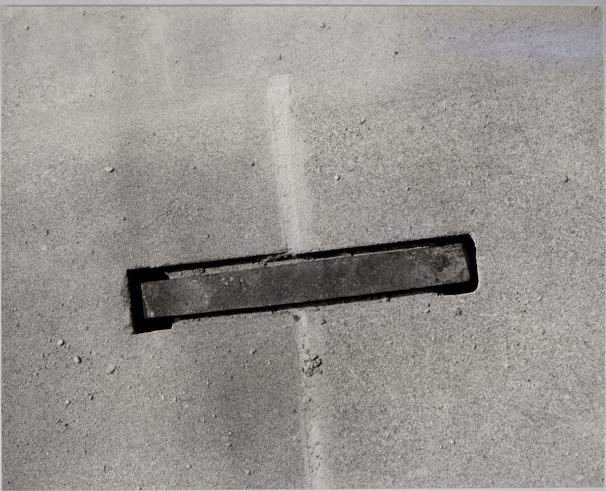 Figure 130
Cramp prior to being set in lead. (CWF 84-TCM-2610-4)
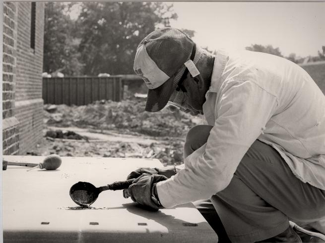 Figure 131
Frank Dunman pours lead to set cramps. (CWF 84-EAC-2457-22)
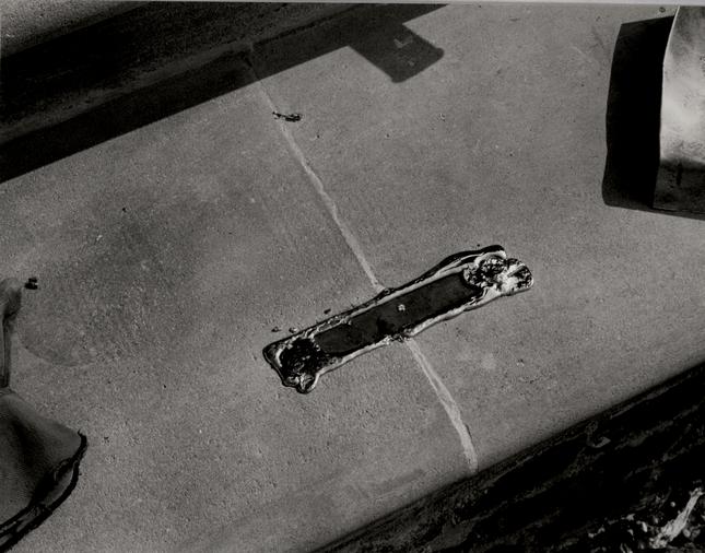 Figure 132
Cramp with lead. (CWF 84-TCM-2610-19)
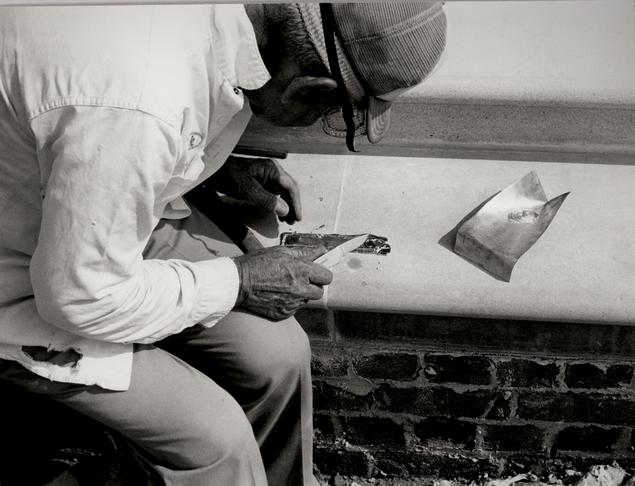 Figure 133
Frank Dunman trims off excess lead from cramp. (CWF 84-TCM-2610-24)
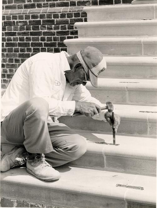 Figure 134
Frank Dunman packs excess lead around cramp. (CWF 84-EAC-2458-27)
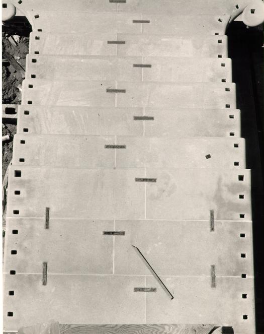 Figure 135
Pattern of cramps in south stairs. (CWF 84-TCM-2609-2)
CHAPTER XVI
NOTES
CHAPTER XVII
DOORS
DESCRIPTION
Each of the Public Hospital's four exterior doorways is centered on an elevation. The principal doorway on the north elevation has a double door of four panels each, with a six light transom above (Fig. 136). The doors on the south, east and west elevations are single six panel constructions with eight light double-row transoms above. Each door has a six inch jamb composed of two cyma moldings and a bead.
DOCUMENTATION
Robert Smith's specifications called for "the outward doors and those to the Middle Rooms to be paneled and the others strong batten doors."1 Specific details were not given and probably became the prerogative of the builder. Nonspecific door references appear in 1786 and 1790: "To cutting through Wall & working in Door frame;"2 and "…working in a door frame."3 No indication is given as to whether this is an interior or exterior door or located in the hospital building proper or one of the outbuildings.
The historic photograph of the north elevation, ca. 1869, offers a view through the open front and rear doors. The width and height of the north pavilion door can be seen as well as a transom and sidelights. The sidelights were evidently added
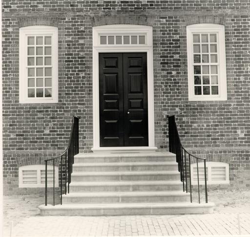 Figure 136
Principal north doors. (CWF 85-FD-406-9)
150
at a later date. The photograph of the south elevation, ca. 1885, shows the central pavilion door, although no details can be seen. This photograph also shows a door and transom in place of a window in the original southeast cell location. By this date, the additional cells in later wings and additional buildings allowed space in the original building to be used for other purposes, as indicated by this door. The height and width of this later door and its transom are correspondingly similar to the conjectural arrangement of the reconstructed south pavilion door.
The Galt drawing depicts the facade entrance as a double door of five panels each. Due to the unknown accuracy of all parts of this drawing, details such as the door were loosely interpreted. In this case, the representation of a panelled double door is probably the most reliable evidence to be derived from the drawing. Heavy lines framing the top panels of the doors might be interpreted as representing a transom. The height relationship between the doors and windows and the belt course are known from the photographs. They provide an indication of the inaccuracy of the Galt drawing and the care that is required in literally relying on early drawings.
PROTOTYPES
In order to determine the various design components of the hospital doors, research and surveys were conducted of a number of original Williamsburg buildings. In a survey of door 151 trim moldings, 24 original buildings dating from 1750-1800 were examined and 5 different trim treatments identified. Of the 24 buildings, 19 had a similar trim molding identified in the survey as type A. This particular trim is composed of two cyma reversa moldings and a corner bead. Two buildings contemporary with the hospital, the Courthouse and Bruton Church tower, were determined to have type A trim. The precedent for this trim provided by the church tower is particularly important because it is known that the builder of the hospital, Benjamin Powell, also constructed the church tower.
The Bruton Church tower also became the precedent for the 1 ½" door trim setback. A similar setback also occurs at the Wythe House and the President's House. The church tower's original west door, along with those at the Wythe House, provided the panel configuration of the hospital's north door. Panel moldings used on all interior and exterior door faces were modelled on those of the Wythe House.
Prototypes for the transoms and door sills were also provided by the Wythe House. The single-row front and double row rear transoms served as models for the hospital's north and south, east, and west doors respectively. A similar single row transom of four lights can be found at the Semple House.
The 8' 6" door height was established by James Waite using the historic photographs. The dimension corresponds to the door height at the Wren Building and the President's House. It 152 is based on a double square ratio, relatively common for eighteenth-century doors.
DESIGN
Doors represent one of the least historically documented elements of the Public Hospital. Robert Smith's specifications refer only to the fact that they should be panelled. The historic photograph of the south elevation shows an obviously later door in place of a cell window, but the rear porch obscures the pavilion door. The historic photograph of the facade shows the doorway with sidelights, but not the door itself. And the potentially inaccurate Galt drawing shows a panelled door with a possible transom, though the latter is seemingly too small in scale to be of any use.
One of the first considerations weighed by the Design Review Committee concerned the east and west doors. There is no direct documentation to suggest the presence of doors centered on the east and west elevations. It was the committee's feeling, however, that doors would have been needed at this location to provide a secondary service access to the building prior to the enclosure of the exercise yards and certainly for access to the yards after the erection of the fences ca. 1790. Whether the doors were added after original construction is simply unknown. Archaeological excavations provided no evidence in the way of porch or stair foundations on the east and west due to the ground disturbance by later periods of construction. An account of 153 replacing the original wooden window sills with stone sills in 1828 documents 36 windows.4 This number would account for one passage window on the end elevations, a logical arrangement assuming there is a door at the east and west.
Because of its function as a public building, it seems extremely likely that the hospital's principal facade entrance had a double door. The three secondary doorways were treated more modestly with one door each. The proportional study of the two historic photographs established the vertical dimension of the masonry opening for the doorway as 10' 4", based on the location of the water table and belt course. once this dimension was established, it was calculated that the logical width of the opening would have been 5' 2", conforming to a double square ratio based on the vertical dimension, a treatment used at the Wythe House. The Wythe House was thus established as the prototype for the hospital doors because of its surviving fabric. The height of the double doors was established at 8' 6", leaving space below the belt course and arch for a single row transom of six lights. The secondary single doors on the south, east, and west were designed to be shorter, 7' 2", with double-row transoms of eight lights. The double-height transom at each end of an otherwise dark passage on the first floor was felt to be a practical necessity. These double transoms were also modelled on the Wythe House (west door) and correspond to the narrower masonry opening and the proportions of the shorter doors.
154Because of a committee decision that all details for an individual element should be derived from a single prototype if possible, the Wythe House provided other details for the doors. In many cases, such as with the trim, setback, and panel arrangement, other appropriate prototypes were recognized as concurring with the details taken from the Wythe House. These details included the door panel configuration, the door panel moldings, the depth of the door trim setback, the wooden sill, and the door trim moldings. The trim moldings were also based on the survey discussed under Prototypes.
A later decision by the committee with reference to the interior design affected the exterior doors. By adding diagonal sheathed boards to the passage side, the east exterior door was of a double thickness. This is discussed in the INTERIOR section of this report.
Modern compromises dictated by safety codes or energy conservation measures were kept to a minimum. At the committee's insistence, the front doors were designed with an authentic inswing. To change the door's swing would have significantly altered the hinges and door trim molding. Because of fire code regulations requiring an outward-swinging door, it was necessary to acquire a variance from the City of Williamsburg which includes the stipulation that the doors remain open during museum hours. In order to accomplish this from the standpoint of energy conservation, Roche/Dinkeloo designed a vestibule for the front doors. The east and west doors were designed with an appropriate 155 in-swing, but the south door in the lobby had to be treated as an exit door with an out-swing. The latter has hidden modern hinges; the committee decided against using fake HL hinges on the interior face. As an added measure of energy conservation, an inset rubber weatherstrip was designed for the underside of the north doors.
An earlier decision to have Roche/Dinkeloo design all interior finishes first influenced the Design Review Committee to decide that interior faces of all exterior doors would not be panelled. In reconsidering this issue, it was decided that both interior and exterior door faces constituted one piece, and to treat the exterior panels in an authentic manner meant that the interior face would have to mirror that configuration.
NAILING PATTERN
The historic nailing pattern for the exterior door frames, similar to that of the windows, was based on research by Mark R. Wenger.5 Documentation for this can be found in the chapter on windows.
CHAPTER XVII
NOTES
CHAPTER XVIII
WINDOWS
DESCRIPTION
The 36 identical windows at the Public Hospital are single-hung, 9/9 light sash with 8" x 10" panes. Each window sash is framed by a 6" jamb inside a 3' 4" x 6' 8" masonry opening. Below each flush wood sill is a bevelled brick course (Fig. 137). The north and south elevations each have 17 windows, including five in the pavilion, while the east and west elevations have one window each on the second floor. Two wooden dead lights are included in the eighteenth-century cell window.
DOCUMENTATION
Robert Smith specified a fairly typical window arrangement in his "Description" of April 9, 1770.
The Windows are 6 hights of Glass 10 x 81 Inches for the hight and 3 for the Width.In other words, Smith described a 9/9 light sash. The specifications for the windows were very general, with the exception of the glass size. If Smith's drawings did not show details, the specifics of the window design would have been left to the builder. These specifics included the size and profile of the muntins and trim moldings, as well as the location of the sill and jamb in the wall. Such details were common and would reflect the local style of building. Smith, however, did not
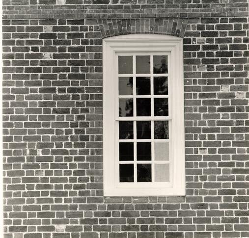 Figure 137
Typical Public Hospital window with two dead lights. (CWF 85-FD-406-1) 158 expect a local builder or carpenter to be familiar with the window grates. Immediately following his single-sentence window specification was a long, detailed description of the interior window gratesand two small, detailed drawings.
From 1773 to 1800, references to hospital windows indicate minor repairs, such as Benjamin Powell's 1775 accounts for "Planking up a Window," "Putting 69 Dead [lights] in Window" and "Planking up Window in Madhouse."2 Accounts for window glass for the hospital record 60 panes purchased from John Prentis over an eight month period in 1774 and an unspecified number of panes replaced by Robert Greenhow in 1788.3 Window repairs and materials supplied by James Anderson in 1789 and 1790 included "stays," "dogg nails," "knees," and a "bar."4
Two nineteenth century references to altered original windows are worth mentioning here. In January 1829, James Guthrie submitted to the directors an account of many repairs and work done during September, 1828. Included in this itemized list was the reference "Putting 36 Stone sills in windows."5 This undoubtedly represents the replacement of the hospital's original wooden windowsills with those of stone and confirms that the builder had probably followed local traditions by using wooden windowsills. By 1828, these sills would have been 56 years old and were replaced because of deterioration or for architectural enhancement. The historic photograph of the north elevation clearly shows these sills and indicates that they were of a dark colored stone. The south elevation photograph also shows them, 159 although in their painted state. The 1829 "Galt" drawing depicts these new stone sills.
Even more important than the reference to the material, is the account for stone sills, which confirmed the presence of 36 windows. Thirty-four windows can be documented through accounts, illustrations and photographs: 16 on the first floor and 18 on the second. The two undocumented windows are most likely those in the second floor of the east and west elevations, completing a total of 36 windows. At the Walnut Street Jail in Philadelphia, Robert Smith provided end elevation windows for staircases and passages, but not for the end cells. Center passage windows, albeit between end chimneys, were the only openings Smith designed for the ends of Nassau Hall.
Another alteration of the original windows occurred in 1843. During the nineteenth century, the hospital benefited from materials produced through new technologies. One such material was cast iron, which began to replace wrought iron for many architectural elements. Cast iron sash, advocated by many asylum reformers, replaced the interior wrought iron grates specified by Robert Smith. These original grilles, ordered by Robert Carter from the Baltimore Iron Works, as well as the cast iron sash, are discussed in the INTERIOR section. The substitution of grilles apparently used on the new west wing and third floor was mentioned in an annual report of January 1843. The annual report of December 1843 stated that the sash were in place.6
160The replacement grilles can be seen in the historic photograph of the north elevation. The availability of the new cast grilles was, no doubt, facilitated by the marketing of cast iron products in the nineteenth century, but also by the prolific period of asylum construction in the United States in the second through the fourth decades of the new century.
Photographs
Much window information came from the two historic photographs. In a memorandum of June 15, 1981, James Waite explained his methodology of using the historic photographs for vertical and horizontal dimensions:
From the photograph of the south elevation I took the horizontal spacing of the voids and solids directly, and fitted them onto a blank elevation whose basic widths of wings and pavilion were provided by archaeology. This gave us the widths of the masonry openings and the brick panels between them: The only limit to this method is the inability to read dimensions too exactly; that is to the specific inch and its fractions. The masonry window openings scale 3'-4" wide, which nicely contains a typical 18th century window arrangement with 9/9 light sashes and normal stiles, muntins, and casings. Windows visible in the north elevation photograph show this arrangement, and are thought to be original.
Using this same method it can be shown that the spacing of windows on either side of the center of the building is the same, one side reflecting the other mirror image. The same method also shows that those windows which can be seen west of the portico in the photograph of the north elevation match the same spacing as exactly as dividers can measure.
The heights of the architectural elements were determined in the same way. The south elevation photograph yields basement window heads (added, probably, but likely in line with earlier example in pavilion), water table, 1st floor window heads, belt 161 course and second floor window heads. Since a scale had been developed for the horizontal units, the vertical units were simply plugged in at the same scale. The photograph of the north elevation was used in the same way and verified the south elevation dimensions. It also gave us the window heights for the first and second floor. These were the same; the total masonry opening scaled about 6'-6". The sloping brick drip cap used below the wood sill brings the total masonry opening to 6'-8".7
In addition to the proportioned dimensions, the two historic photographs and the "Galt" drawing confirmed the fenestration pattern for the north and south elevations. The third floor windows seen in the 1885 photograph have jack arches that are thought to be copied from the original windows. These windows have a cast iron sash of 28 divisional squares. Cast iron sash appear on every visible wing window in the north elevation photograph. The photograph of the south elevation, however, probably taken in the 1880s, shows cast iron sash only on the third floor windows. The windows on the first and second floors had been altered with later 4/4 light sash, indicating that these rooms might not have been used for cells at that time. The easternmost cell window on the first floor is shown in the south elevation photograph as a door, another indication of non-patient use of the former cells. It is also very likely that at least one pavilion window of the second floor had been altered to provide access to an enclosed sun porch or solarium.
PROTOTYPES
The choice of a window trim molding was based on the surviving original window trim on Bruton Church tower during its 162 restoration in 1903. This molding was the same type chosen for the door trim: two cyma moldings and a bead. One of the best surviving window trim moldings of this type from which the details could be taken was that of the Wythe House. The Wythe House windows thus became the prototype for the other window details: muntins, stiles, rails and sill. The bevelled brick course beneath the window is a relatively consistent Williamsburg detail like that of the water table brick, which it resembles. Based on a survey of brick windowsills in the Historic Area, the, mortar joint was found to be slightly less than 1/4" as an average.
Single hung windows were chosen for the Public Hospital based on previously documented cases that indicated their common usage:
A double hung window is one in the case of which both sash slide vertically. It was customary in eighteenth century Virginia to use "single hung" windows,,i.e. windows in which only one sash, the lower, was movable. The architects of Colonial Williamsburg, however, have found only a single instance of the use of double hung windows in colonial times. During the restoration of the Peyton Randolph House positive evidence was found which indicated that the windows of the early two-story west part of the dwelling had been double hung.8
DESIGN
In its first meeting on June 3, 1981, the Design Review Committee agreed to establish the masonry opening of the windows at 3' 4" x 6' 8", based on the proportional analysis of the historic photographs. Other details taken from the photographic evidence included a 9/9 light sash, 8" x 10" lights, and a 6" 163 jamb. The decision to use flush wood windowsills with a bevelled brick course below was based on the prevalence of such examples in Williamsburg. The jack arches above the windows are discussed in a separate chapter. The committee decided to base the window details on one source and to adhere to the evidence that the fenestration pattern was unevenly spaced.
Early in the project it was decided that all the windows would be operable, that simulated crown glass would be used, and that a Plexiglas sheet would be detailed for the interior of each window as an energy conservation measure. The committee decided that if it was necessary to darken the windows for any night time activities, shades would be used. The project manager later ruled against this decision and installed Venetian blinds in the second floor windows.
The decision to use a window trim molding similar to the one chosen for the door trim was based on the original window moldings from Bruton Church tower. Benjamin Powell, having built the tower in 1769, would very likely have used the same moldings on the Public Hospital. Another logical prototype would have been the contemporary Courthouse, if its architectural report had not offered the disappointing information that the fire of 1911 had destroyed the original window trim: "The window sash, frames, trim and sills are new. The single molded trim is the type which was commonly found through Williamsburg in the eighteenth century."9 After a precedent had been established, 164 the Wythe House window trim served as the actual prototype due to its similarity and surviving condition.
The decision to use a modern spring balance mechanism rather than ropes and weights was a modern compromise that became less satisfactory after the specified brand was inexplicably changed to one whose location was not hidden (Fig. 138).
The window frame was designed so that its top edge would correspond to the top edge of the mortar joint of the rubbed jamb. Examples in Williamsburg revealed that frames corresponded to both the top and the bottom of mortar joints.
The two (fake) dowels representing a mortise and tenon joint on the top mire corners of the architrave are based on the Wythe House windows (Fig. 139). These same mire corners proved to be a problem after the assembled frames arrived at the site. Due to long storage at the site prior to installation and a period of high humidity, the corners pulled apart and had to be corrected with marine glue and screws.
Two initial elements of the design were later eliminated. Wrought iron pins on leather straps were designed to secure the windows but were later eliminated when it was found necessary to secure the sash with screws. The other element, changed due to a lack of precedent, was that of a drip at the bottom edge of the wooden sill.
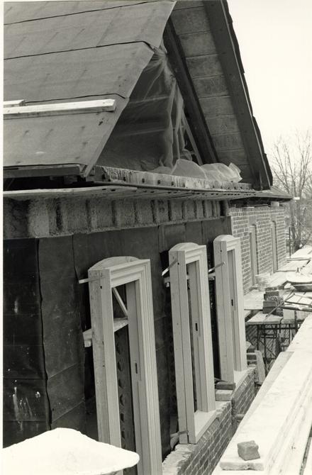 Figure 138
Window frames awaiting brick jambs. (CWF 84-EAC-1347)
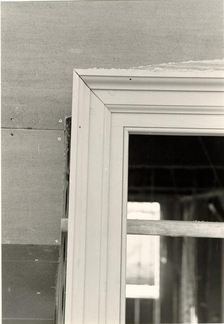 Figure 130
Detail of window frame corner. (CWF 84-TCM-1046s)
NAILING PATTERN
Mark R. Wenger researched and designed the historic nailing pattern for the windows. Because the window frames arrived already assembled from the TMS Millwork Shop, the wrought T-head nails were not functional. The following explanation is quoted from Wenger's research memorandum:
In 18th century buildings, window frames were often composed of solid members pinned together at the corners and chased out on their interior faces for sash weights. Stops were nailed on from the inside (See Wetherburn's Tavern, Deg. #112, and the Carpenters' Company Rulebook, pl. x.). If a three member architrave was desired, the backband or cyma reversa was applied with nails to a solid member which contained the two planes of the architrave. This applied molding occasionally laps over the pegs which connect the solid frame corners.
The backband was nailed on the "swell" of the ogee, close to where it meets the fillet. From photos, it appears that three nails were considered quite enough at the jambs and two at the head of a fairly small window (about 22 x 40"). For larger windows, it seems that four and three fastenings would suffice if spaced roughly equal to one another (See Moorehead Photo Album, "Photographs of Windows and Doors: f.1111. In a photo from the Kendrew Collection (A-Ph-Ken 79), it appears that nails were spaced about 4" from the corners.10
DEAD LIGHTS
On April 15, 1776, Benjamin Powell was called upon to make repairs to the Public Hospital windows, putting in 69 dead lights and "planking up" a window.11 Again in November of that year Powell was paid for "Planking up Window in Madhouse."12 These references to replacing broken window glass with wood could be interpreted as a specific measure taken at the hospital in response to particularly violent patients who were breaking the 166 glass in their cell windows. Other coincidental evidence, however, suggests another reason as well.
It is only in 1777 that dead lights were in evidence at the hospital. Before and after that time glass replaces glass. Despite William Pitt's advertisement in the Virginia Gazette of May 1776 in which he offers window glass for sale, the use of wooden dead lights is most likely the result of an imported glass shortage.13 This supposition is supported by similar occurrences at the Williamsburg Gaol and Capitol. During 1776 and 1777 dead lights and "wood panes" were being used by Phillip Moody and Benjamin Powell for repairs to windows at the Gaol and Capitol.14 Yet another 1777 reference to dead lights occurs at the church of Stratton Major Parish in King and Queen County where it was "Ordered that the church wardens do agree with some person to put dead lights into the Church Windows & Grub up the bushes in the Church yard."15
Glass, in addition to other imported goods, was in shortage after 1775 for a number of reasons. First of all, after the dissolution of the House of Burgesses in 1774, the Association for Non-Importation imposed their own sanctions against imported British goods, including glass. This cut off the supply of British glass, and the importation of non-British glass also became difficult. Further, it has been pointed out that much of the glass supply in Williamsburg may have been depleted due to a severe hail storm in which many windows were reportedly broken.16
167Regardless of why dead lights were used, the Design Review Committee could not ignore the evidence that they were at the Public Hospital in 1777. It could be easily argued that the use of dead lights was only a temporary measure due to the glass shortage. However, the reference to whole windows being "planked up" suggests a remedy for the breaking out window glass by chronically violent patients. By adding two dead lights to the eighteenth-century cell window, we attempt to convey to the visitor some of the reality of violence at the hospital (Fig. 137).
CHAPTER XVIII
NOTES
CHAPTER XIX
ARCHES
DESCRIPTION
The jack arches at the Public hospital form the top of each masonry opening (Fig. 140). Each arch is composed of "rubbed" and gauged brick that forms a flat top and a segmental bottom. Between the window frame and the arch is a plastered brick filler space.
DOCUMENTATION
The evidence for the window jack arches was derived from the two historic photographs of the Public Hospital. On both the north and the south elevations, jack arches with flat tops and shallow segmental bottoms can be seen. In the photograph of the north elevation, ca. 1869, segmental bottom jack arches can be seen above the windows flanking the portico. The presence of this form on the windows of the third story, which was added in 1839-40, indicates that the original jack arches from the first and second floors were copied for those of the new floor. The windows of the pavilion, seen in the photograph of the north elevation, were apparently altered because they show a different sash and flat bottom arches. The south elevation photograph, ca. 1885, shows the flat and segmental jack arches only on the third floor. Again, it is likely that the original arches were copied for the third floor
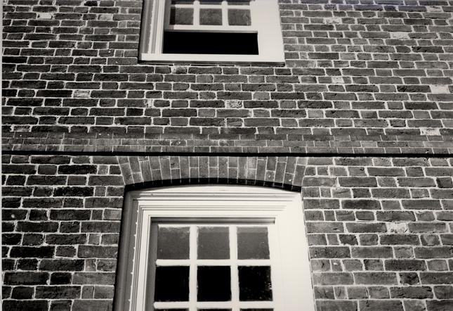 Figure 140
Typical first-floor jack arch. (CWF 84-TCM-2659-13A)
171
windows. The first and second floor windows in this photograph have obviously been altered and different sash added, resulting in a flat bottom arch. It is also interesting that the flanking east and west wings, added in 1844 and 1840 respectively and shown in this photograph, also have the segmental bottom jack arches over the second and third floor windows. No door arches can be seen in the photographs or drawing. It was very common, though, to use the same type of arch for all openings. Therefore, the use of this same type of arch for the doors is conjectural, but entirely reasonable.
The Galt drawing of 1829 depicts flat lintels with corner blocks for the first and second floor windows on the north facade of the hospital, while showing basement windows with arched tops. No other evidence of a written, pictorial, or photographic nature confirms this arrangement. It is believed that this element of the drawing might represent a proposed alteration.
PROTOTYPES
The only example of a similar jack arch form in Williamsburg, with a flat top and segmental bottom, is at the Governor's Palace. The detail is conjectural and probably based on one or both of two contemporary examples in the area: the Nelson House in Yorktown, 1725-40; and Rosewell, 1725-44. In addition, a similar jack arch form can be found in the Shirley dependencies. Other Virginia examples of this relatively rare 172 type of arch include Poplar Grove in New Kent County and outbuildings at Cleve in King George County. Examples outside of Virginia include the Stigerwaslt House in Rowan County, North Carolina; the Daniel Blake Tenements in Charleston, South Carolina; the India Wharf Stores Building in Boston; the Town Hall, Gaol and Courthouse in Bridgetown, Barbados; the Peggy Stewart House, Annapolis; the Manor House, Wardsworth, England; and the Miles Brewton House (rear, second floor), Charleston, South Carolina.
The space between the top of a window frame and the bottom of a segmental arch can either be filled with brick or wood. Williamsburg examples and the survey conducted by Herbert Claiborne (Comments on Virginia brickwork Before 1800) establish the use of brick as the more common filler. Brick arch fillers in Williamsburg occur at the Ludwell-Paradise House, the President's House, the Palmer House, the Archibald Blair Kitchen, the Griffen House and the Greenhow-Repiton Office. In some instances the brick was plastered as either a refinement or to cover the small brick chips necessary for such a small space. The Palmer House, Archibald-Blair Kitchen and the Ludwell-Paradise House all have plaster covering the brick filler. Other Virginia examples identified by Claiborne with brick rather than wood in-fill are: St. John's Church, 1734; Stratford Hall, 1730; the Westover Kitchen, 1730; the Barrett House, 1754; Kenmore, 1752; Smith's Fort, mid-eighteenth century; the Shields House, and the Custom House at Yorktown.
DESIGN
The design of the brick jack arches was based on the two historic photographs of the hospital. The dimensions of the arches was taken from James Waite's proportional analysis of the historic photographs, which corresponded to a common window opening size. The decision to use a brick filler was based on the precedents listed above. The committee felt that, due to the shallowness of the in-fill or filler space, the small brick chips would have been messy and probably covered with plaster. After first suggesting that no rubbed brick would be used below the water table, the committee decided that an exception would be made with the basement window jack arches. This decision was based on the fact that most non-rubbed, non-gauged basement jack arches are composed of all headers in either a flat or segmental rowlock arch. Amore elaborate window arch would most likely have been rubbed and gauged.
Two important changes occurred after the initial design phase. As a result of the brick panel mock-up, the specified 3/32" joint between the gauged brick was recognized as being too large. A survey of original gauged brick arches confirmed that 1/16" was a more common size. This smaller size was then established as the average size for all gauged brickwork, including the belt course.
The other change, involving the north door arch, was only apparent after construction. After the wider north door arch was seen in relationship with the narrower window arches, 174 the angle of side splay was questioned. The soffit arc of both the doors and the windows had been drawn from the same point, creating a steeper angle of splay and a higher filler area for the wider door opening. Examples of ungauged work indicate that the splay is generally taken from the same point as the arc. With finer gauged work, the solution is to draw the soffit arc of a wider opening from a lower, independent point, which results in an identical angle of splay but with the same rise as the other openings. Even though the method of using one point for drawing both the splays and arc seems to be more logical, examples at Rosewell and Shirley suggest independent points.1 Since the single east, west, and south doors had splays of a less pronounced difference, only the north arch was rebuilt. New drawings, PH205A and PH20B were drawn to correct this situation.
One further question was resolved without alteration. Should a splayed arch spring from the middle or the base of a course? Examples of both were found, Rosewell and the Palmer House being representative of each. The hospital arch design, with its spring from the bottom of a brick, was left unaltered.
CONSTRUCTION
During construction the most common problems were presented by gauged brick joint size and the proper alignment of the voussiors. Whole or parts of arches were frequently rebuilt during construction. For a full discussion of the manufacture of arch bricks see the materials section.
175The following photographs document the sequence of arch construction (Figs. 141 - 149).
 Figure 141
In preparation for an arch, flashing is placed over the window frame and splayed jamb bricks are cut and put in place. Note the two wall brackets to which the brick wall is attached by hooks set in a mortar joint. (CWF 84-TCM-1594s)
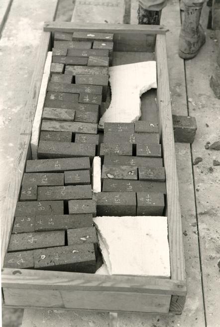 Figure 142
Numbered arch voussoir bricks were lifted up to the scaffolding by forklift. (CWF 84-TCM-1593s)
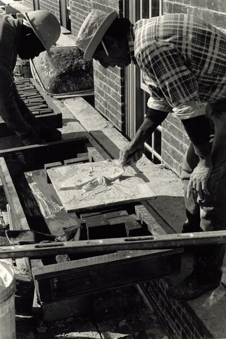 Figure 143
"Putty" mortar without sand is mixed in small quantities for each arch. (CWF 84-EAC-1346s)
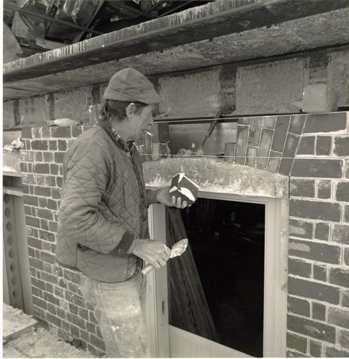 Figure 144
A wooden form work is used to produce the segmental bottom while stringline helps produce an even top. Melvin Haynes, shown here, and Earley Thompson constructed all of the arches. (CWF 84-FD-1268-6s)
 Figure 145
The tights 1/16" joints are achieved by use of a hammer. (CWF 84-FD-1268-4s).
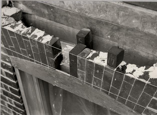 Figure 146
In order to tighten the joints in the whole arch one to three voussoirs were remade slightly larger. (CWF 84-TCM-1038s)
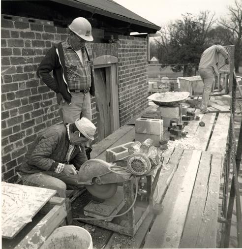 Figure 147
Adjustments to individual pieces were made on the scaffolding with a masonry saw. Melvin Haynes is shown cutting slivers off a brick. (CWF 84-FD-1720-3s)
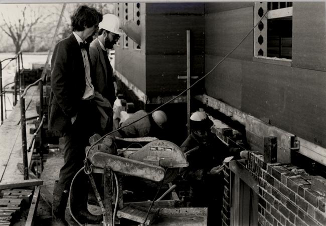 Figure 148
Constant supervision was required to catch oversize and crooked joints. Most arches had to be adjusted or rebuilt at least one. Edward Chappell and Travis McDonald are seen here discussing an arch with Earley Thompson. (CWF 84-WJG-1504s)
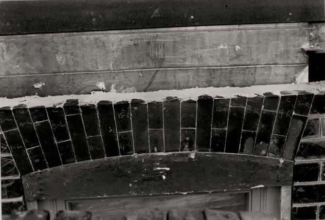 Figure 149
A completed arch. (CWF 84-WJG-1500s)
CHAPTER XIX
NOTES
CHAPTER XX
BELT COURSE
DESCRIPTION
The Public Hospital belt course is a three course band of rubbed and gauged brick that encircles the building at the second story floor level. The belt course is laid in a Flemish bond pattern with narrow putty joints and projects from the wall one inch (Figs. 150-151).
DOCUMENTATION
The historic photograph of the south elevation, scaled by James Waite, revealed that the belt course was about 7" high. This would account for three rubbed courses. The bond could not be determined from the photograph.
PROTOTYPES
Belt courses are a standard feature of Georgian architecture. Typically, they are three courses high, equalling the space of two courses of field brick. The exception in Williamsburg is the molded brick belt course at the Lightfoot House. In Williamsburg, belt courses project from the wall an average of one inch: Wythe House, 1 ¼"; Brafferton Hall, 1"; President's House, 1"; and the Wren Building, ¾". All of these belt courses are composed of rubbed brick laid in a Flemish Bond pattern with lime putty mortar joints.
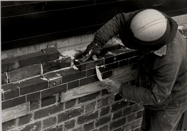 Figure 150
The belt course was constructed of slightly wedge-shaped bricks in order to achieve a tight face joint. bill Brinkly of Snow, Jr. and King, shown here, constructed the belt course. (CWF 84-TCM-1082s)
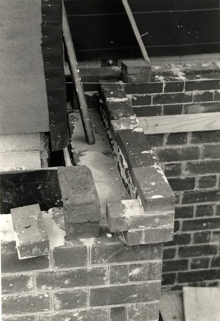 Figure 151
The belt course under construction as it turns the corner of the pavilion. (CWF 84-TCM-1080s)
A number of original buildings were surveyed to determine whether the mortar joints below and above the belt course should be struck. Examples indicated an inconsistent practice and a full range of options. The Ludwell-Paradise House and the Brafferton represent the option chosen for the hospital, that of an unstruck joint below the water table and a struck joint above.
DESIGN
The Design Review Committee's choice to include a belt course in the Public Hospital design was based on evidence from the historic photographs and the Galt drawing. Belt course dimensions are ;based on the photographic proportional analysis and the dimensions of two field brick courses: headers 2 1/16" x 3 ¾" x 3 ¾"; stretchers 2 1/16" x 3 ¾" x 7 19/32"; closers 2 1/16" x 3 ¾ x 1 13/16"; corners 2 1/16" x 3 ¾" x 7 29/32".
CHAPTER XXI
CORNICE
DESCRIPTION
The Public Hospital's modillion cornice is composed of a crown molding (a cyma recta and cyma reversa), a corona or fascia, a soffit, modillions (with a cyma reversa molding) and a bed molding (an ovolo and a cyma reversa) (Fig. 152).
DOCUMENTATION
Robert Smith
Robert Smith made two references to the cornice in his "Description": "… 5 Thousand of Inch Boards for Cornice to the Eves…" and " . . . a neat Mundelian Cornice around the whole …."1 No more specific references were made to the actual appearance of the cornice.
Photographic/Pictorial
Smith's specifications are confirmed by the Galt drawing, which depicts a modillion cornice with a curious line of marks on the wall just below it.
The two historic photographs both show a cornice believed to be the original. The cornice seen in both photographs is that of the third floor. Because of its Georgian scale, it is believed that the cornice was reused when the roof was raised for an additional floor in the Greek Revival period.
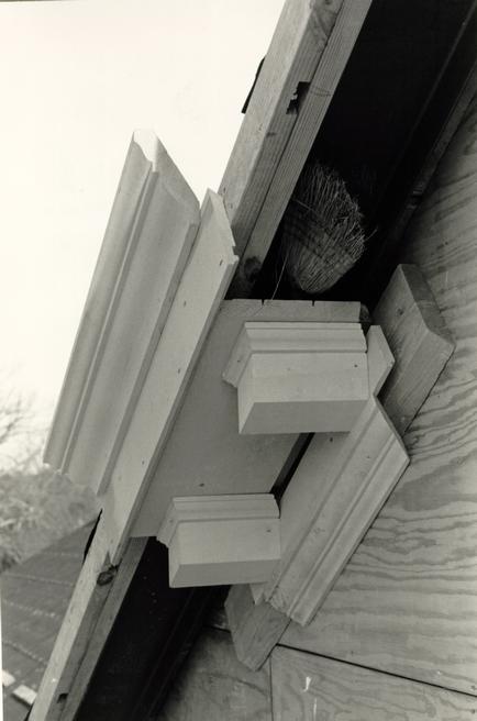 Figure 152
Cornice mock-up showing the various parts. (CWF 84-TCM-1659s)
180
The fact that the cornice on the central pavilion pediment, seen in the photograph of the south elevation, matches the rest of the cornice, leads to the conclusion that the pediment as well as the cornice was reused (see PEDIMENT chapter for a discussion of this). Using the proportional method described earlier, James Waite scaled the cornice seen in both photographs for dimension.
PROTOTYPES
Using on the proportions taken from the historic photograph of the hospital, the cornice was based on that of the Palmer House. This cornice was a typical type, similar to the lower cornice of the Bruton Church tower. The raking modillions of the pediment cornice were based on those of the Prentis Store and Courthouse cornices and will be discussed in the PEDIMENT chapter. The fascia/soffit interface of a fascia drip and a recessed soffit were recognized as elements of the most common surviving Williamsburg example, found at Bassett Hall, the Lightfoot House, the Public Records Office, Peyton Randolph House and the Tayloe House.
DESIGN
A significant alteration to the cornice design occurred when it was decided, in the fall of 1983, to use wood rather than concrete shingles for the roof. To accommodate the addition of 1" x 3" shingle lath (nailed onto the concrete roof deck), the crown molding needed to be raised in order to support the starter 181 and first course of shingles. An additional blocking strip behind the fascia was proposed. This alteration increased the size of both the fascia and the soffit by ¾". By doing this, the fascia became larger than the crown molding, 5 3/8" and 4 ¼" respectively. This situation was found to exist on a number of Williamsburg buildings (the Taliaferro-Cole, Coke-Garrett and Powell-Waller houses). More importantly, the historic photograph of the hospital's south elevation was reexamined and its cornice scaled, which indicated that the crown molding was larger than the fascia. The modillion stayed at its original length of 8 1/8" in order to keep within the sizes of known local prototypes (Powell-Waller 8", Brafferton Hall 8 3/16", Bruton (main cornice) 8 ½"). As a result, a ¾" - 1" space was created between the end of the modillion and the fascia, a condition found to predominate on original cornices in Williamsburg and elsewhere in Virginia. The crown and bed moldings did not change. Lath strips were not necessary for the cupola cornice.
CONSTRUCTION
Two problems were associated with the construction of the cornice. The first problem, which became known immediately, was the result of an incorrect installation of the roof steel. In effect, the steel "rafters" were 3 ½" short, requiring the addition of blocking members behind the crown molding, fascia and soffit (see drawing 70-106, SK84-2-15 "Sketch of Addition [sic] 182 Blocking Required @ Main Cornice to Accommodate Existing Structural Conditions") (Fig. 153).
Ill-fitting modillions on the east and south cornice were the first sign of a complex and cumulative problem. In addition to millwork production problems, the soffit was found to be cupping. Two kerfs were cut into the back of the remaining cornice on the south and west to prevent further warping. Part of the problem was no doubt the result of a flat grain wood that was more prone to warping. Gaps around the modillions were filled with caulking and unfinished portions of the cornice were painted to keep moisture out.
Two new problems then became apparent: mitered fascia corners had split open and the soffit had cracked in the location of the kerfs. Both of these problems, as well as the warped soffit, were the result of a wet soffit that had pushed outward. Through the contractor's negligence, the soffit had absorbed moisture due to wet blocking against which it had been nailed, to unprimed field cuts, and to inadequate protection from rainwater. The fascia was also opening at the corners due to a design problem which did not allow enough lateral movement for the soffit on the inner side, resulting in a "growth" toward the fascia.
Solutions to this problem were more easily proposed for the unbuilt cornice sections than for the already built east, south and west elevations. Three changes were implemented for the north cornice: the top of the modillion band was cut off so
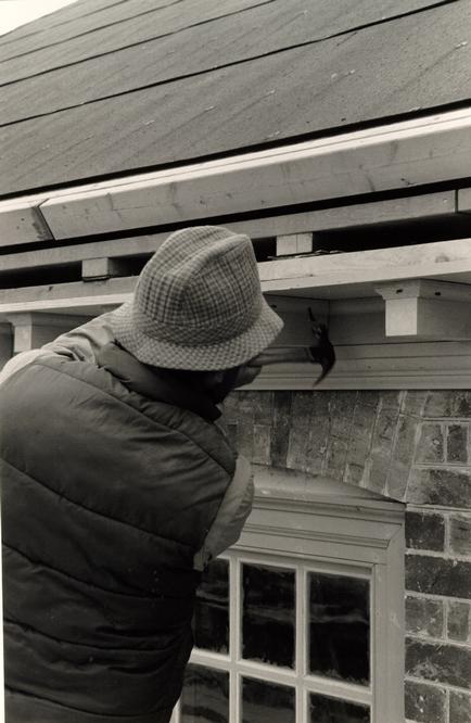 Figure 153
Modillions are nailed on with wrought T-head nails. First method of cornice blocking which resulted in a damaged soffit. Note 2nd 2x4 member for crown molding. (CWF 84-TCM-1655s)
183
that the soffit could expand over it during any lateral movement; the middle and lower 2" x 10" blocking members were reversed so that the ember against the soffit was non-continuous, providing more air space (Fig. 154); and dry blocking members were used. Committee recommendations to rebuild the corners were not implemented.
A more serious, long-range problem resulted from the contractor's continuing failure to protect the cornice from rainwater. Due to the late decision to substitute wood for concrete shingles, application of the hospital roof covering was delayed. Because of the contractor's schedule to take advantage of the masonry contractor's scaffolding, the construction of the cornice was not delayed to coincide with the roof installation. Consequently the cornice remained unprotected for four months during the rainy season and became severely mildewed in places. Despite advice that much of the cornice be rebuilt, the contractor was allowed to simply repaint all affected areas and to fill the open mitered corners.
NAILING PATTERN
The historic nailing pattern for the cornice was researched and designed by Mark R. Wenger and Wenger's recommendations are quoted here:
2
- I.Cymatium
- A.A. This member is always nailed through the cyma reversa into the corona or fascia. This may be seen in the photos of the Semple Quarters (N1615), the Public Records Office (N5748) and Prentis Store
Figure 154
Cornice blocking. Reversing the middle and lower soffit blocking members provided an air space for the soffit. (CWF 84-FD-1267-1s) 184 (Moorehead Album, "Photographs of Cornices, Rakes, etc.", f. 4).- B.Gable end Cymatia seem to be nailed through the cyma recta, into sheathing behind as seen in the photos of the Semple House (N1001) and Prentis Store (Moorhead Album, "Photographs of Cornices, Rakes, etc.", f. 4).
- C.Eave Cymatia are often not nailed through the upper, cyma recta portion of the molding as seen in the photos of Semple Quarters (N1615).
- D.However, since sheathing is to hit the back of the cymatium, as shown in Whiffen's eave detail for the Palmer House (Houses . . . p. 65), the cymatium should be nailed through the cyma recta.
- E.Because none of the above nailing would be dependent on joist locations, nails should not be on centers with the assumed structural module of 24" (This module is very common in the 18th century).
- F.Spacing of these nails falls mostly in the range of 18"-24". Upper and lower nails in the cymatia should not be exactly centered over one another.
- G.These nails were often T-headed as seen in the cornice and baseboard at Market Square Tavern. This particular shape was one of several customarily used for finish work. (See Lee H. Nelson, "Nail Chronology . . .", Technical Leaflet 48, American Association for State and Local History.)
- V.Bed Molding
- A.The top edge of the bed molding was frequently nailed through the top of the ovolo into the modillion band above, or possibly into the blocking behind. Examples of this can be seen in photos of Stratford (#253), the Public Records office (63-AK-179) and the Semple Quarters (N1618).
- B.On brick buildings the Bed Mold could be nailed on its lower edge through the Cyma Reversa into a beaded board "hung" from the face of the plate as shown in Whiffen, p. 54, or it could be nailed to blocking [?] as at Stratford (#253). In the Stratford photo this blocking is not visible, but the nails testify to its presence.
- C.Nails were probably somewhat smaller than in the Cymatium. Spacing does not appear to relate to structures for obvious reasons. At Stratford the spacing often exceeds 185 24". From a modern point of view, it seems wise to space fasteners no wider than about 24".
- D.These nails in the Bed Mold are occasionally smaller than those in the Cymatium or Corona. (Carter's Grove - Hallway Cornice)
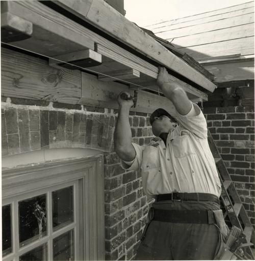
CHAPTER XXI
NOTES
CHAPTER XXII
PEDIMENT
DESCRIPTION
A frame pediment surmounts the north central pavilion (Fig. 155). Its random-width board tympanum is framed by a raked modillion cornice and has a lower weathering covered with shingles. Centered in the tympanum is a bull's eye window.
DOCUMENTATION
Gibbs/Rowe
Robert Smith's "Description" did not mention a pediment, but the "Articles of Agreement" with Benjamin Powell specified that "the north front of the middle building to have a neat Pediment the South East and West ends to be hipped."1
A subsequent reference documented by Gibbs/Rowe that specifically mentioned the pediment was made in 1828 to "shingling 2 pediments."2 Unless this reference indicates that a pediment had been constructed on the south pavilion, for which there is no evidence by this date, the pediment or pediments in question may have been on two new buildings.
Photographic/Pictorial
The Galt drawing shows a pediment above the north pavilion as specified by the builder. No details other than a
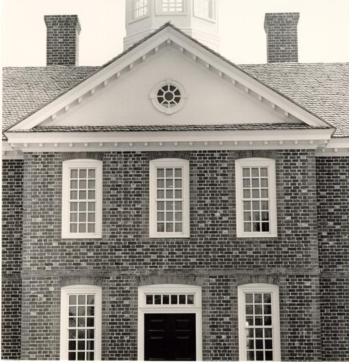 Figure 155
North pediment. (CWF 85-FD-407, 1s)
188
bull's eye window, a lower tympanum weathering, and a raked modillion cornice can be distinguished.
It is the historic photograph of the south elevation that has yielded the greatest amount of information regarding the pediment. From this photograph, James Waite calculated the overall dimensions and the angle of the slope (34 degrees, 8/12). Clearly seen is the flushboard tympanum face, the bull's eye window with its four keystones, the raked modillion cornice, and the tympanum weathering. The reliance on this evidence was predicated on the assumption that the pediment was originally constructed on the north pavilion and was moved to the south when displaced by the Greek Revival portico. The pediment's scale is decidedly Georgian rather than Greek Revival.
PRECEDENTS/PROTOTYPES
While examples of pavilion pediments in Williamsburg are few, the Wren Building's being the most like the hospital's, they were a relatively common eighteenth-century feature on public buildings. Questions concerning the hospital's pediment were ones that involved the material of both the tympanum and its weathering. If the pediment had indeed been moved, was the tympanum originally wood, or had it been brick, rebuilt in wood? The other question concerned the tympanum weathering or the lower sloping face of the pediment. Was it originally flashed with metal, as the south elevation photograph indicates, or was it shingled like the roof?
189Examples of tympanums on eighteenth-century brick buildings can be found constructed in both wood and brick. The decision to design the hospital's tympanum in wood was based on the south elevation photograph and examples of wooden tympanums on such buildings as the Wren Building; Blandfield, 1771; Mount Airy, 1758-67; and Rocky Mills, c. 1750. The Wren Building's tympanum has been documented by a daguerreotype.
The precedent for tympanum weatherings was overwhelmingly strong for a shingled treatment. Eighteenth-century examples from Philadelphia to Virginia were consistently shingled.
DESIGN
The scale and character of the entire pediment seen in the historic photograph of the south elevation indicated that it had been moved from the north side. Based on this assumption, the scale and dimensions of the pediment were derived from the proportional analysis described in chapter XVII. The photograph also provided the primary evidence for a wooden tympanum, with eighteenth-century examples to document such a treatment. The use of shingles to cover the tympanum weathering was based on eighteenth-century precedent.3
Details of raked modillions were based on original examples at the Prentis Store and the Courthouse of 1770. A subsequent change involved changing the ratio of the pediment's slope from 8.125/12 to 8/12, retaining the 34 degree angle.
190The bull's eye window was originally modelled on a similar window at Woodlands, 1794, in Louisa County. The committee felt that this design was too Federal in style and, instead, chose one used by Robert Smith at Carpenters' Hall and the First Presbyterian Church at Carlisle, Pennsylvania. The two part trim surrounding the east circular window at Bruton Church, a cyma reversa and a bead, was the prototype for the window's frame.
CONSTRUCTION
The tympanum was constructed of flush shiplap sheathing applied to plywood on metal studs (Fig. 156). TMS Millwork Shop of Richmond fabricated the bull's eye window, which was then constructed at the site. Shingles were installed and the cornice cut to fit them (Figs. 157 - 158). Tympanum shingles were first installed without copper sisalcraft strip flashing, but were later reinstalled with it; lead-coated copper flashing was placed at the tympanum/shingle juncture.
Due to a problem with the roof framing during shingle installation, the pediment cornice had to be disengaged from its original blocking and renailed to new blocking. This required adding new wire nails to secure the upper cornice, thereby making the wrought T-head nails ineffective.
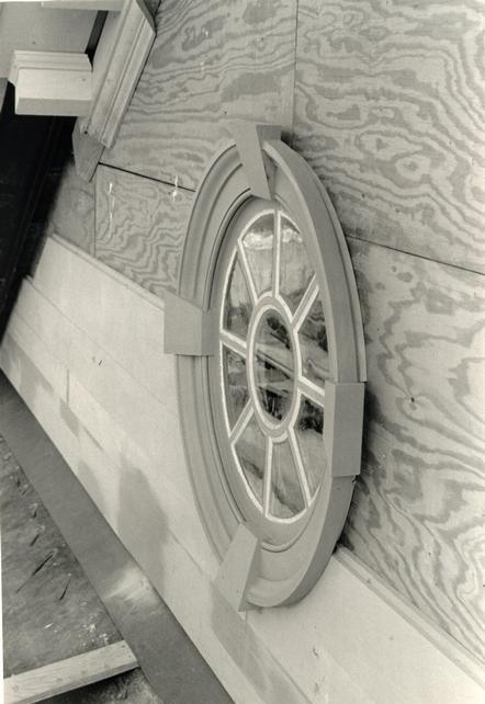 Figure 156
Construction of tympanum sheathing and bull's eye window. (CWFF 84-TCM-1660s)
 Figure 157
Installation of pediment shingles. (CWF 84-TCM-1640s)
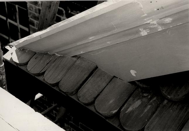 Figure 158
Pediment cornice is cut to fit on installed shingles. (CWF 84-TCM-1641s)
CHAPTER XXII
NOTES
CHAPTER XXIII
ROOF
DESCRIPTION
The Public Hospital's hipped roof is a steel-frame and concrete plank structure covered with cypress shingles (Fig. 159).
DOCUMENTATION
Robert Smith did not mention the roof in his "Description." However, the "Agreement" with Benjamin Powell, the builder, mentioned the roof and specified that its form be hipped and that it "be covered with plank and good Cypress Shingles."1
Two references were made in 1803 and 1808 to some sort of roof platform.2 If these were not a decorative deck, they most likely referred to a scaffolding of some type. The Galt drawing shows no such deck, however. Nor does the drawing show dormer windows, referred to in 1810, which indicates that the reference was most likely for the Convalescent House or perhaps the Galt Cottage.3
The original shingle roof, that had been repaired from time to time, was finally replaced with slate in 1829 in order to make the building more fireproof.4
The Galt drawing depicts the originally specified hipped roof. The south elevation photograph and the Ramn
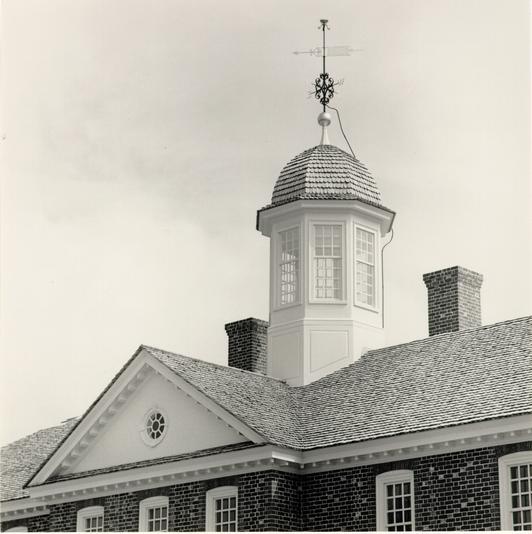 Figure 159
General view of roof showing swept valley.
193
lithograph show that the roof was later changed to a gable, an alteration probably carried out when the third floor was added in 1840.
DESIGN
Powell's "Agreement" and the Galt drawing formed the rationale for the hospital's reconstructed hipped roof. The proportional dimensional analysis established the roof slope as 33 degree 10, which conforms with a common colonial rafter to joist ratio of 5 to 3.
Conventional steel framing forms the principal structural system (Fig. 160-161). To this framing rectangular concrete planks were fitted and tack-welded at their tongue-and-groove metal edges (Fig. 162). Asphalt roofing felt forms the intermediate layer of covering. The roof covering, first specified to be Hendricks cement shingles strip-flashed and nailed directly to the concrete deck, was changed to wooden cypress shingles (see Shingles in the Materials section).
Research into the kick of the roof indicated that late eighteenth-century buildings had only a slight kick caused by the seating of the starter shingles on the crown molding of the cornice.5
CONSTRUCTION
Problems related to the steel roof framing later affected both the cornice and the shingles. In the case of the
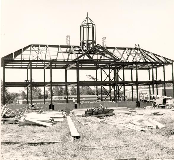 Figure 160
Steel framing of Public Hospital roof.
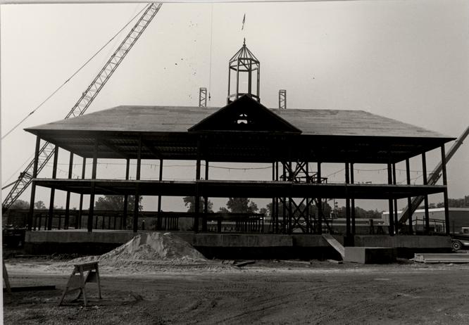 Figure 161
roof with concrete planks on steel framing. (CWF 83-FD-5396-7s).
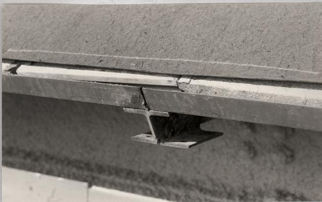 Figure 162
Edge of roof showing concrete plans fit together with tongue-and-groove edges and covered with roofing felt. (CWF 84-TCM-1576s).
194
cornice, the roof steel was found to be 3 ½" short around the entire building, requiring additional cornice blocking: On the pediment roof, the steel was installed with a severe deflection, which later necessitated that each shingle lath strip be individually shimmed.
CHAPTER XXIII
NOTES
CHAPTER XXIV
CHIMNEYS
DESCRIPTION
The Public Hospital's two chimneys flank the cupola just south of the roof ridge (Fig. 163). Each of the chimneys is 3' 1 3/4" square laid in Flemish bond with a three-course corbel cap.
DOCUMENTATION
Gibbs/Rowe
Robert Smith's "Description" specified the symmetrical arrangement of the two chimneys: "The Bricklayers must order it so that the chimneys come out in the Roof at Equal distance from the middle otherwise they will have a very ill Effect. This may be easily done."1
Building and repair records prior to 1800 include a chimney alteration in 1778 and a repair in 1779.2 The type or extent of alterations is unknown
Archaeology
Excavations during the first season in 1972 revealed the chimney foundations in the basement. James Waite's report accompanying his 1972 drawings interpreted the location of the foundations in relationship to their placement in plan:
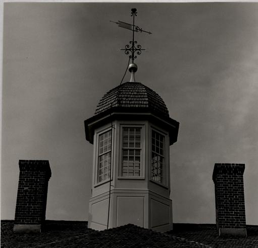 Figure 163
Public Hospital chimneys from the south side.
197
Because the only fireplaces were in the Keeper's Quarters on the first floor and in the directors' meeting room on the second floor, the chimneys were central and off-set to the south in order to correspond to these locations.Foundations for two original chimneys exist, much reworked from their original form. These occur to the east and west of the original cellar space, projecting into the cells south of the Passages. The foundations of the chimneys also project north into the Passages. This is the builder's attempt to locate the chimneys as close to the ridge of the building as possible, still leaving space for doorways between the Hall and the Passages.
The length of the west chimney foundation to the south is seen as the builder's method of providing support for a second floor fireplace, since a fireplace on the first floor would certainly have occurred over the relieving arch in the cellar, fragmentary remains of which have been discovered.3
Photographic/Pictorial
Depicted in the Galt drawing are chimneys believed to be shown in their original size and location. When the chimneys were raised to accommodate the third floor, it can be assumed that they remained unchanged as to location but were, perhaps, rebuilt with a different style of cap. The caps seen on both chimneys in the historic photograph of the north elevation and the east chimney cap seen in the photograph of the south elevation have a two-course corbelled band a couple of courses down from the top. The Galt drawing, on the other hand, shows a corbelled cap at the very top of the chimney. This latter treatment is similar to the chimney cap at the Courthouse of 1770 and is felt to be the more likely original treatment. Seen in 198 the photograph of the south elevation is an obviously enlarged west chimney. This alteration occurred after 1869 because both chimneys can be seen in their smaller size in the photograph of the north elevation.
DESIGN
The Public Hospital chimneys were designed from a number of sources: written, photographic, pictorial and archaeological. Their location is well documented through both archaeological excavations, as well as the views, photographs and the drawing of the building. The height of chimneys, both domestic and public, varies considerably. Central chimneys rising from a hipped roof were found to be about six feet in average height. This height also corresponds to the height of the hospital's rebuilt chimney as seen in the photograph of the south elevation. The fact that it was off-set to the south of the ridge line also accounts for the lower height of the chimneys seen from the north in the Galt drawing. Based on the Courthouse of 1770's chimney, the hospital's chimneys were designed in Flemish bond with a three-course corbel cap.
Due to the function of the reconstructed Public Hospital, it was decided that the chimneys would not be carried down through the building as working chimneys. Initially, Roche/Dinkeloo had accepted the suggestion that the chimneys rather than the cupola be used for intake/exhaust needed for the heating system. Based on this, one chimney was to be used for 199 intake and one for exhaust. Calculations for the heating system then necessitated that both chimneys be used for exhaust. After exploring various methods of using the cupola for air intake, the committee could find no acceptable solution that used the chimneys and cupola in combination for this system. A final solution was adopted, which called for both the air intake and exhaust vents to be located in the west exercise yard. The chimneys were eventually chosen as the logical place to conceal restroom vents.
A question regarding bond, finish courses and a plaster wash prompted the committee to reconsider the probable number of flues and the chimney design. The supposition held that if each chimney contained two or more flues, the bond would be common and not Flemish. The probably number of flues (two for the kitchen and one each for the keeper's quarters and the directors' room) did not resolve the issue, because two adequate flues could be accommodated in a square Flemish bond chimney stack. It is possible that the chimneys may have been common bond but, due to the number of Flemish bond examples, the committee decided not to alter the design.4
The chimney cap was reexamined and its design, based on the Courthouse of 1770, was found to represent the most common extant type, having two courses of corbelling with two straight courses above.
The Design Review Committee considered the use of rubbed brick for the chimney corners but decided against it for 200 lack of relevant prototypes. Lead-coated copper flashing for the chimneys was designed in a cricket and step flashing pattern commonly used in the Historic Area. Subsequent to the design, a late eighteenth-century example of chimney flashing was examined in Petersburg at Strawberry Hill. In this example V-shaped lead flashing was used only on the upper elevation of the chimney; the sides contained only a mortar wash between the brick and the shingles; the lower elevation contained only a brick drip course.5 While the Design Review Committee recognized that the hospital's flashing may not be entirely accurate, a concession was made to insure that the roof is watertight.
CONSTRUCTION
Construction of the chimneys did not deviate from the working drawings. A brick veneer of 4 ½" in a Flemish Bond was tied to ½" plywood sheathing, which in turn was attached to a steel frame (Fig. 164). The chimney tops are sealed with a 3/8" steel plate through which the 4" vent rises.
Because of the contractor's negligence, the top plates remained unprimed and without flashing for a long period, causing rust stains on the brick and mortar.
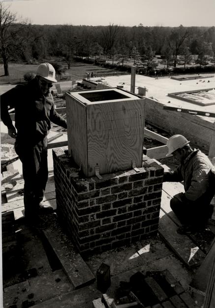 Figure 164
Construction of chimneys. CWF 84-TCM-1048s).
CHAPTER XXIV
NOTES
On the two chimneys in the central portion of Strawberry Hill are remains of the original waterproofing system utilized around the chimneys. This has been preserved because the wings to the house were raised from one story to two stories early in the nineteenth century. The wings now enclose this portion of the chimneys.
A thick piece of lead was nailed to the chimney face on the upper side. In the valley where the roof meets the chimney, the flashing was bent and ran several inches up the roof. Here in the valley it was nailed to a wedge-shape cant strip that was in turn nailed to the roof sheathing. Narrow round-butt shingles apparently lapped over the flashing. The lead flashing rounded the corners slightly, but was not used on any of the other chimney faces. Instead, on the sides the sheathing and shingles butted tight against the brick. A drip course was provided for on the lower edge. About one inch below the drip, the sheathing and shingles butted against the chimney. To keep water from penetrating where shingles met the chimney, mortar was laid on top of the shingles and against the brick. A lot of this mortar remains on the chimney, leaving a ghost of the missing shingles. Mortar was also placed at the top of the flashing to keep water from getting behind the flashing.
The east chimney still retains its original lead 202 flashing secured with wrought nails. The lack of nail holes on any chimney face other than the top, along with the shingle ghosts in the mortar indicates that the flashing was only on the top surface.
The west chimney is a false chimney, built on boards on the attic floor. The stack was necessary to give a symmetrical exterior facade. Though its flashing has been removed, there is much evidence left demonstrating that it was waterproofed in an identical manner to the eastern example. Both chimneys are common bond stacks retaining their original grape-vine joints.
THE PUBLIC HOSPITAL:
AN ARCHITECTURAL HISTORY AND
A CHRONICLE OF RECONSTRUCTION
Architectural Research Department
Colonial Williamsburg Foundation
Williamsburg, Virginia
1986
CHAPTER XXV
CUPOLA
DESCRIPTION
The Public Hospital's cupola is octagonal in plan and fitted with 9/12 light sash. Its base is composed of raised panels on all but its east and west faces. Above the cornice is a shingled roof and a weather vane (Fig. 165).
DOCUMENTATION
There is no mention of a cupola in either Robert Smith's "Description" or Benjamin Powell's "Agreement." William Nelson's letter to Robert Cary in London regarding a weather vane for the hospital is early confirmation of a cupola. It can only be assumed that Smith's drawings depicted the cupola. Repair records at the hospital in 1803 and 1808 refer to the "Steeple" and "Steeple Shingling" respectively, providing further evidence of a cupola.1 The 1808 reference also mentioned "leading" in association with the cupola repairs, no doubt a repair to flashing. The first direct reference to the cupola comes from an 1817 list of repairs by Thomas Sands and James Guthry: To repairing Cupelow to 38 feet Cornish.
To 37- 1/3 feet flashey at 6d
To 19 feet planser. To 32 feet Cant bord.
To putting ogees to 4 windows.
To 2 side Caising to Windows.
To 2 sets Moldings round the Cupelow next the boll.Figure 165
Public Hospital cupola. 204 To glasing 16 pains glas to Do.
To mending planking to Do. To 16 feet old bedmold.
To piecing Cornerbord. To splising joist.2
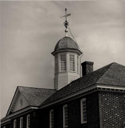
This account of repairs is important for establishing the documentation for a number of elements. Most importantly, the references to "glasing 16 pains glas" and "Caising to windows" confirm that the square-headed windows shown on the Galt drawing were glazed rather than louvered.3 While there is one reference to "putting ogees to 4 windows," the number of windows cannot be determined from this because the account was for repairs and it cannot be assumed that all the windows needed "ogees." Similarly, the dimensions given for the other elements being repaired cannot be taken as the total length or size. The reference to "38 feet Cornish," however, is important. If this dimension is taken at a minimum, and probably the total length, it equals 4' 9" of cornice per side. This is a close approximation of the cupola cornice width (4' 6" per side) independently established through comparisons with other cupolas. The rest of the 1817 references confirm that the cupola was composed of common elements.
While the hospital's shingle roof was entirely replaced by slate in 1829,4 an account in 1831 to "repair and tin the cupola" indicates that the cupola's shingle roof was replaced by tin.5 Ultimately,in 1840, the entire cupola was replaced by a larger one, more appropriate in size for the increased height of 205 the building and more in style with the Greek Revival taste (Figs. 55, 56, 68, 166).6
Photographic/Pictorial
The first known elevations of the cupola, and of the building for that matter, appear on two maps of Williamsburg: the Bucktrout Map, ca. 1800 (Fig. 167), and an unidentified map, early nineteenth century (Fig. 168). Even though these drawings are fairly crude and can offer no specific design details, they do confirm its existence.
Because the original cupola was replaced in 1840, no photographs of it exist. The two historic photographs and the lithographs show the Greek Revival cupola that replaced the original one in 1840. The Galt drawing, however, does show the original cupola (Fig. 169). Depicted in this drawing is an octagonal cupola, centered and straddling the ridge of the hipped roof. Design elements include panels, indicated on six sides of the octagonal base; square-headed windows on at least six sides; a cornice; domed roof; pinnacle; and weather vane. Based on eighteenth-century stylistic trends, it is felt that the shape of the cupola roof shown in the drawing is slightly exaggerated by being too pointed. When judged against contemporary comparative examples, the overall proportions seem to be correct. Using proportional analysis, the cupola's approximate dimensions are: overall (bottom of base to top of spindle)=38'-39'; bottom of base to bottom of ball= 25'; pinnacle=3'-4'; weather vane (bottom
Figure 166
Small watercolor drawing of Public Hospital attributed to Lizzie Galt (Swem Library, College of William and Mary).
Figure 167
Detail of the Bucktrout Map, ca. 1781, showing Public Hospital.
Figure 168
Map of Williamsburg after 1800 showing a depiction of the Public Hospital on "the Bedlem or Madhouse Lots."
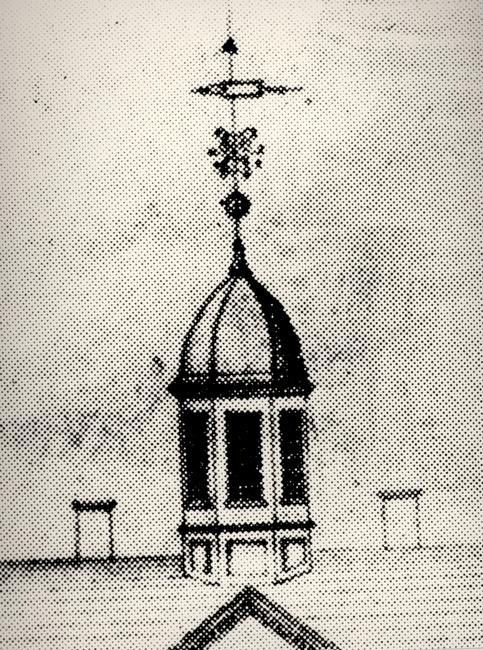 Figure 169
Detail of the Galt Drawing Cupola (CWF 81-2989).
206
of ball to top of spindle)=13'-14'; elevation width at windows = 9'. The Bucktrout plan of Williamsburg also depicts the Public Hospital with a cupola, albeit crudely drawn.
PRECEDENTS/PROTOTYPES
Cupolas in the eighteenth century were generally found on public buildings rather than domestic buildings. Williamsburg was no exception to this rule. Prior to the 1770s, the most important, non-ecclesiastical public buildings in Williamsburg had cupolas, with the exception of the Public Records Office. Cupolas on the Wren Building, the Capitol and the Governor's Palace have all been documented through various sources and thereby reconstructed. These reconstructed buildings and their cupolas, however, all represent the early eighteenth century: the Capitol, 1701-1705; the Wren Building, 1716; and the Palace, 1706-20. The difference in form between these early eighteenth-century cupolas and the last two cupolas erected on public buildings in Williamsburg, the courthouse and the hospital, is considerable. Early cupolas, at least those represented in Williamsburg, were tall and narrow, usually tiered, not unlike the plates of Gibbs' London church steeples shown in Vitruvius Britannicus. A more common form found later in the century was a lower, wider, one-stage cupola.
Another trend can be seen in the general shape of the cupola roof. While those earlier in the century are more bell-shaped with kicked-out or flared edges, the later eighteenth 207 century examples show a more rounded form with straight sides. The Capitol, Wren Building (Fig. 170) and Palace are all examples of the flared roof while the hospital and courthouse cupolas represent the later form (Fig. 171). The 1870s photograph of the Courthouse shows a roof that is lower and more sloped than that of the reconstructed roof.
Robert Smith and Philadelphia
Cupolas by Robert Smith shown an evolution from a flared, angular, bell-cast roof form to one more rounded with relatively straight sides. Smith's major work in which he uses the flared form is St. Peter's Church, Philadelphia, 1758-61 (Fig. 10). This form reflects a general trend in cupola designs. A building contemporary to. St. Peter's though with unclear Smith connections, is the Pennsylvania Hospital. This hospital's cupola, constructed between 1755 and 1757, was much like St. Peter's (Fig. 172). The Pennsylvania Hospital's west wing was designed with a much more rounded, neoclassical roof form by the time of its construction in 1793-96 (Fig. 173). other late colonial buildings by Smith also show this evolution: the Walnut Street Jail, 1773 (Fig. 15) and Carpenters' Hall, 1770 (Fig. 174). The Market House or "Head House," is an example of a post colonial cupola of this type in Philadelphia.
This change in form could be the influence of Colin Campbell's Vitruvius Britannicus, 1731, which shows a proliferation of round roof cupolas. Smith is known to have
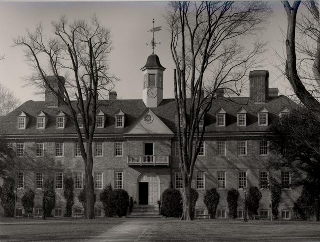 Figure 170
The "Wren Building" at the College of William and Mary (CWF X62-JC-446)
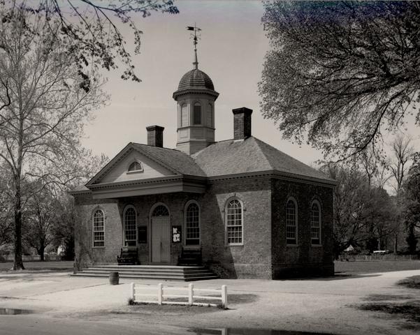 Figure 171
Williamsburg Courthouse, 1770 (CWF 82-FD-3136).
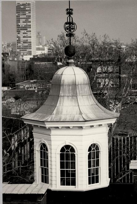 Figure 172
East wing cupola of the Pennsylvania Hospital ca. 1755-57.
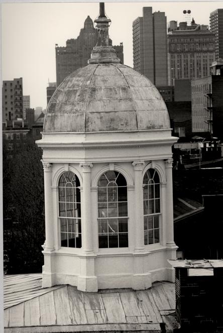 Figure 173
West wing cupola of Pennsylvania Hospital, ca. 1793-99.
 Figure 174
Carpenters' Hall, ca. 1770.
208
purchased a copy of this in Philadelphia in 1756. If the Courthouse constructed in Williamsburg in 1770 was by a local builder, such a book could well have offered prototypical designs for its rounded cupola roof. The connection of the Courthouse cupola with Robert Smith is tenuous at best.
DESIGN
The design of the cupola was a process of numerous studies and discussions. Initiated with a design in 1972, studies of the cupola were again started in the summer of 1981 and continued into the fall of that year.
A set of drawings produced in 1972 represented the first reconstruction scheme for the Public Hospital. These drawings included a cupola design, the sources of which were described in "Architectural Notes on First Preliminary Drawings, December, 1972":
Making the assumption that a cupola was present on the first building, one has been shown on the reconstruction drawing. It has been adapted from four sources: a) the cupola on the Courthouse of 1770; b) the cupolas shown on the 1830s buildings in the nineteenth century illustrations; c) the cupola shown on the illustrations of Smith's Walnut Street Jail, Philadelphia; d) the cupola on Carpenters' Hall, Philadelphia, by Smith.7
This composite cupola was octagonal in form, 7' 4" in width and 19' in height from base to roof (Fig. 175). Its architectural elements included a flush-sided base, round-headed louvered openings with architrave and keystones, pilasters flanking each opening, and a very round roof form. The
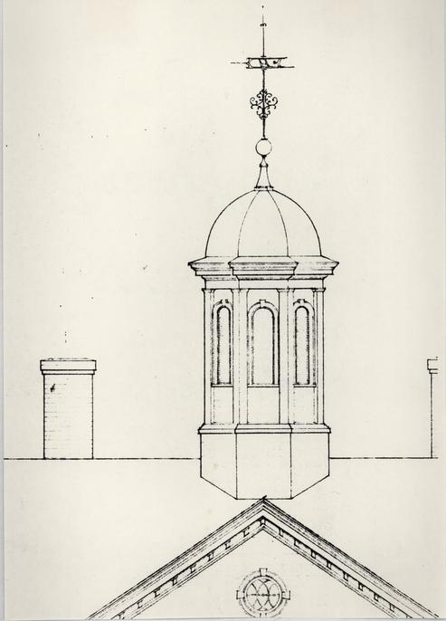 Figure 175
The first cupola scheme.
209
interpretation governing this design was explained in the 1972 report:
As the details of the cupola are conjectural, so is its size. The cupola as shown does not overpower the building, and may be thought to be in keeping with its somewhat retiring character. The cupola shown is, in fact, slightly smaller than the cupola on the Courthouse of 1770. The final bulk of the cupola may in fact depend on a series of mathematical ratios and proportions, as used by some eighteenth-century builders here.8
After an extensive cupola analysis conducted as part of the design review process in July 1981, this earliest cupola design was considered inadequate in its massing. In fact, it was smaller than any of the prototypes mentioned, at least two of which were on buildings smaller than the hospital. A new study, based on the massing of the cupola in the Galt drawing, was based literally on the proportional dimensions taken from that source (Fig. 176).9 These dimensions were approximately 8' 9" for its width and 20' 8" for its height from base to roof.
The third and final phase of cupola studies was begun in July 1981 and subsequently evolved until the final design was approved in October of that year.10
Two designs were first drawn as a comparison, one adapted from Carpenters' Hall cupola (Fig. 177) and one from the Galt drawing (Fig. 178). Both of these schemes used the approximate elevation width from the historic drawing, 8' 10". The Carpenter's Hall scheme measured 21' from base to roof as compared to the "Galt" scheme of 22' 6". Fundamentally, the difference between these two schemes, excluding details, was the
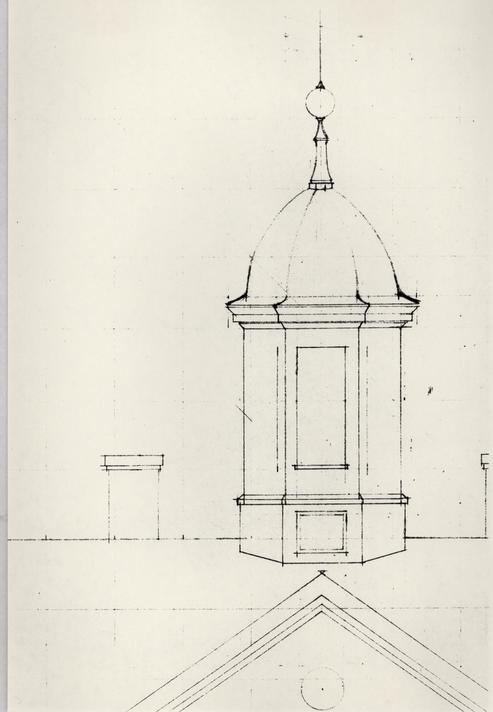 Figure 176
First cupola study based on the Galt drawing.
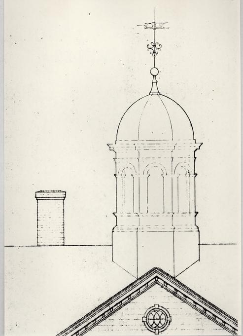 Figure 177
Cupola scheme adapted from Carpenters' Hall.
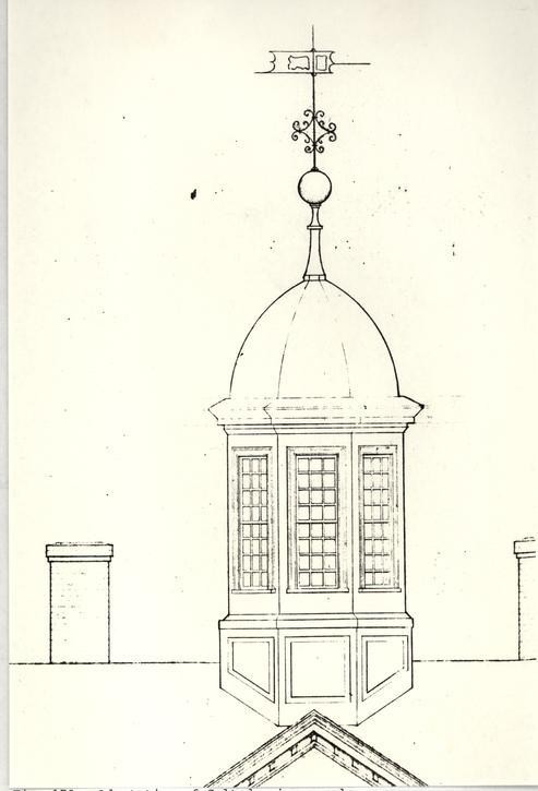 Figure 178
Adaptation of Galt drawing cupola.
210
shape and pitch of the roof. The Carpenters' Hall scheme represented a more rounded roof form. The "Galt" scheme represented a literal interpretation of that drawing with an attenuated, more steeply pitched roof. Based on cupola research partially discussed in the Robert Smith section of this chapter it was felt that the roof form should be more rounded than that shown in the Galt drawing. The width of the cupola elevation was also increased to 9'. This decision was made on the comparative dimensions of Smith cupolas: Nassau Hall, 12'; Pennsylvania Hospital, 12' 6"; St. Peter's Church, 10'; Carpenters' Hall, 9'; the Walnut Street Jail, 11'.11 Cupola dimensions of Nassau Hall and the Walnut Street Jail are approximate, based on illustrations. In addition, the Courthouse of 1770's cupola is 9' 6". In light of this evidence, the earliest cupola drawing with a width of 7' 14" was considered too narrow, and the approximate size and proportions indicated by the Galt drawing were used.
In order to provide for an adequate supporting structure, the octagonal base of the cupola was designed to straddle the roof ridge of the central pediment where it joins the roof of the main building. This arrangement, although awkward, is found at Carpenters' Hall and the Courthouse of 1770.
After an initial recommendation to use the openings and trim of the Carpenters' Hall cupola as prototypes of Robert Smith elements, i.e. round-headed openings, pilasters and impost blocks, the committee decided that the Galt drawing should act as 211 the prototype since it had fulfilled that role with other details. Consequently, the openings were designed as conventional square-headed windows. The first study was one of flat-headed windows with keystones (Fig. 179). Because they are believed to be accurately reconstructed, the cornice and trim moldings of the Courthouse of 1770 were approved as prototypes.
Additional studies involved the proportions of the windows in relationship to the face of each cupola side. After experimenting with a narrower and a wider sash, 6/6 and 16/16 lights respectively, it was decided to rely on an historic glass size of 8" x 10" and to use a 9/12 light sash. Wooden sills similar to those on the other hospital windows were also approved. A discrepancy arose between an earlier drawing of the cupola roof used for the working drawings and a later drawing. This 5" in height represented the difference between the "Galt" roof form and the very rounded roof of the Courthouse; the higher dimension was approved based on an earlier decision regarding the shape of the roof.
Keystones were studied in two different forms: a simple, flat, one piece form versus a more elaborate type with three parts. The eventual decision to omit keystones was based on a research memorandum, as were other decisions about degree of elaboration:
Keystones: Despite an extensive search, we can discover no really relevant examples of square headed frame openings with keystones. The closest parallels I can find are several interior doorways at Liberty Hall, Frankfort, Kentucky (c. 1796) and the wooden first and
Figure 179
Final cupola study based on Galt drawing; keystones were omitted. 212 second-story window frames of Carpenter's Hall. The latter are within masonry openings and the whole building has more elaborate detail than is documented for the Public Hospital.Although rounded arched windows seem more common for 18th-century American cupolas, and these windows most often have keystones, those few square headed cupola windows that we know lack keystones. The later represent a wide range of date and scale: Wren Building, Macpheadris-Warner House, Bruton, Maryland State House, and Mt. Vernon. The most relevant decorated cupola windows I find are the segmental ones in Richard Munday's 1739 Colony House in Newport, and these are part of a larger design scheme that includes projecting cornice fragments. Further, I think we can agree that Munday's overall design has a funky character that removes it from the realm of the Public Hospital.
Most important, perhaps, is the picture that emerges concerning the general character of the Public Hospital design. It was an important pubic building, apparently the object of considerable public pride, and it was designed by a distant Philadelphia architect. On the other hand, we can assume (I think) that its details were the result of local, traditional ideas and craftsmanship. The Bruton tower and original Courthouse cupola seem to owe more to endemic buildings than to published prototypes or Philadelphia designs. Complexes as grand as Menokin and Jefferson-authored houses show simplifications in execution. They were, to some degree, "adapted to the Nature of the Country by the Gentlemen there." Our assumptions about the frame tympanum, simple bevelled watertable bricks, indigenous moldings, etc., are in part a product of this idea. To attempt to embellish the cupola with undocumented details places us too far out on a subjective limb.
Panels below the windows: Include with the possible exception of the east and west faces. While we are uncertain about the form or existence of panels on the east and west faces of the cupola, we should not allow this design problem to lead us away from the use of a feature that the Blanton drawing clearly indicates for the other faces. There seems to be more evidence for their use here than at the Capitol, Wren, Bruton, and the Courthouse.
I assume that these would be conventional raised panels, like those on exterior doors and shutters. The 213 east and west faces might have short rectangular panels or pairs of triangles. The use of such irregular shapes can be roughly paralleled by the undersides of pulpit sounding boards, St. Andrew's-cross doors, the spandrels above the door at Carpenters' Hall, and (perhaps) the balcony of the R. I. Colony House (see Downing & Scully, plate 63). The other option is to omit the panels from the two faces.
Modillion cornice: Uncertain, but probably omit modillions. Cupolas with and without modillion cornices can be found on buildings with both modillion and plain cornices. The strongest evidence against the use of modillions here is the fact that none are visible in our print of the Blanton drawing, while they do seem to be visible on the cornices of the main building and flankers. The early cupola at the Pennsylvania Hospital does, of course, have a modillion cornice. On the other hand, Carpenters' Hall does not; like a sizable number of other examples (including the Chowan Co. Courthouse), it has a fairly plain entablature. The Jeremiah Lee house cupola and the upper stages on the Maryland State House dome seem to have only plain cornices. The old Delaware State House example has very small dentils.
In sum, there are prototypes for almost any combination of cornice elements. Based on the Blanton drawing and the general simplicity that we perceive in the Hospital cupola, I believe our best course would be a simple cornice without modillions.12
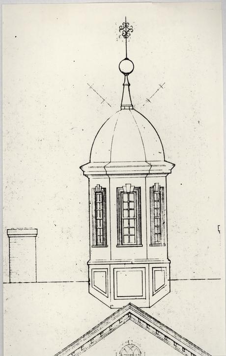
Raised panels on the cupola base had been included on detailed drawings sent to the working drawings contractor because of their appearance in the Galt drawing. When applied to all eight sides of the base, awkward panel configurations were formed on the east and west faces because of the juncture of the roof ridge with the cupola. It was decided to omit these east and west panels since their presence cannot be seen in the Galt" drawing or documented in any other way. The committee considered omitting all panels, but ultimately decided to follow the configuration of the Galt drawing.
214Research on modillion cornices, quoted above, resulted in the committee's decision to omit this element altogether.
At one point in the design process the cupola was considered part of a solution to get fresh air into the heating and cooling system. Various schemes included a partially open sash, louvers around the base and a recessed screen in a window. These were all rejected because of their negative visual impact. When it was calculated that a cupola size would be inadequate for the volume of required air, six possible locations for air intake were considered. The most logical of these was a grade level grille inside the west exercise yard. This worked well for a number of reasons: 1) it eliminated any adverse visual impact on the exterior of the building; 2) it was also acceptable as an air exhaust solution, freeing the chimneys from such a function; 3) a location at grade was economical for running ducts from the mechanical system in the basement; and, 4) its location was out of public view.
The use of the hospital attic affected, to some extent, the cupola's interior. Because of the attic's intended function as a work space, the cupola needed to be open and unobstructed in order to act as a skylight. Ideas for any type of viewing platform were rejected because of this, but a removable ladder was recommended and approved for occasional viewing. The interior finish was changed from gypsum board to random width sheathing with wrought T-head nails (Fig. 180).
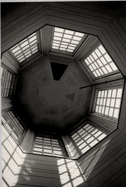 Figure 180
Sheathed interior of Public hospital cupola (CWF 85-TCM-344-36).
The 15,000 lb. cupola was designed as a steel cage (Figs. 181, 182), integral with the roof framing, with an applied interior and exterior wooden frame (Figs. 183, 184). Backing consists of 2 ply 3/8" plywood. Both the cornice and the base panels were designed following eighteenth-century construction techniques rather than those of modern practice (Fig. 185).
CONSTRUCTION
Only minor problems plagued the construction of the cupola. On the exterior, ill-fitting and damaged panels constituted the most serious problem. On the interior, steel flanges had to be trimmed and plastic conduits for the lightning system had to be rerouted in order for the sheathed boards to fit. After construction began, batt insulation was recommended and installed in the cupola side walls (Figs. 186, 187).
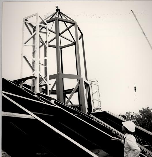 Figure 181
Travis C. McDonald inspects steel cage of cupola (CWF-83-DS-4953).
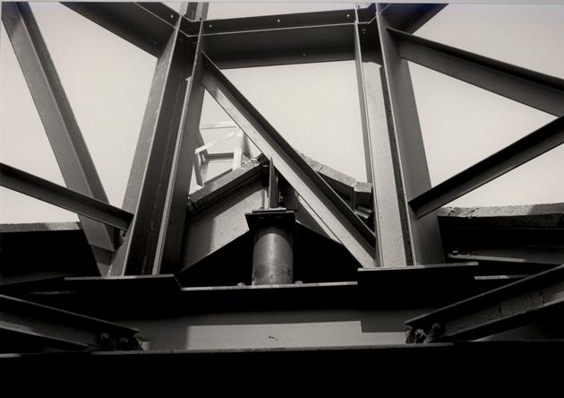 Figure 182
Detail, steel framing of cupola (83-TCM-5396-26s).
 Figure 183
Wooden framing members bolted onto steel framing to accept wooden sheathing.
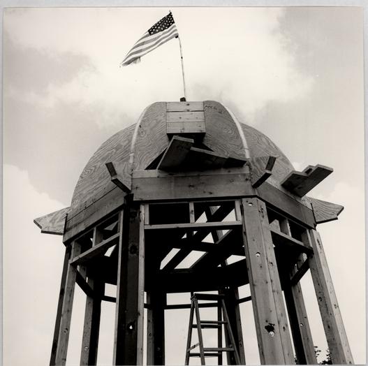 Figure 184
Wooden framing for roof.
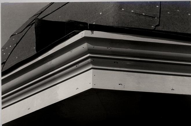 Figure 185
Detail of cupola cornice (83-TCM-5397-16s).
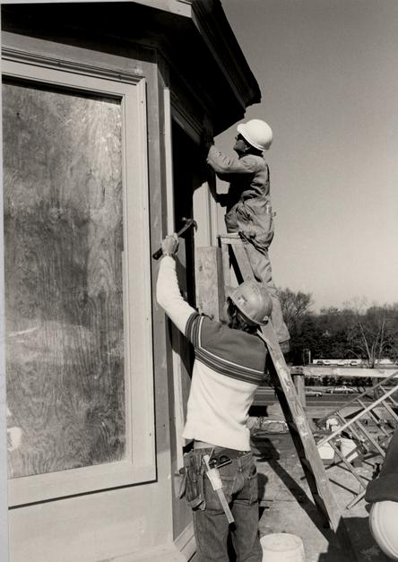 Figure 186
Exterior trim is applied to cupola (84-TCM-1054s).
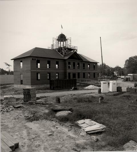 Figure 187
Cupola construction (83-FD-5512).
CHAPTER XXV
NOTES
CHAPTER XXVI
WEATHER VANE
DESCRIPTION
The Public Hospital weather vane is a 10' 1" high composition of hand-wrought elements consisting of a 15" hollow copper ball, a tapered iron spindle, compass arms with cardinal letters, scrollwork above and below the arms, a 5' 6" long banneret vane, and a modern lightning protection device disguised with scrolls as a decorative top piece (Fig. 188). With the exception of the copper ball and the stainless steel lightning device, all parts are hand-wrought iron. The ball, compass letters and banneret vane are gilded.
A BRIEF HISTORY OF WEATHER VANES
Although the history of weather vanes can be traced back to classical times, their development during the Middle Ages is most relevant to eighteenth-century designs. Medieval nobility were distinguished by the square cloth banners carried into battle and placed on castles. These banners were kept by metal rods unfurled for easy identification by metal rods and eventually were transformed into a thin metal form of iron, copper or bronze. The lesser nobility were permitted to carry rectangular cloth pennants or bannerets that became the prototypes for later eighteenth-century weather vanes.
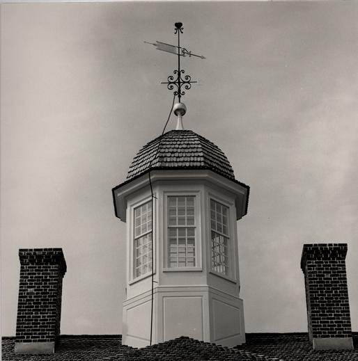 Figure 188
The Public Hospital weather vane with the attached lightning conductor. (CWF 85-FD-407-7s)
By the Georgian period, the English nobility had grown to such great numbers that heraldry and heraldic motifs lost their former status and meaning. It has been suggested that it was at this time that architects began using these symbols as a decorative design on buildings. Jones, Wren, Gibbs, Chambers, Dance, et al. used a similar banneret vane form to top off cupolas and steeples. This form was characterized by a guidon shaped "flag" that extended beyond the rod or spindle on which it swivelled. The tail of the banneret ended in one or two points, in a waved or straight form. To the front of the banneret extended a barbed, arrowhead like pointer. Scrollwork and other decorative designs on the banneret, spindle or compass points provided an endless variety of forms. A common feature of a weathervane ensemble was a fixed hollow metal ball at the juncture of the cupola roof or steeple pinnacle and the vane. Another common element was a symbolic motif fixed on the spindle above the banneret, frequently capping the whole vane ensemble. Vanes were also symbolically or descriptively embellished by punched-out letters, dates or symbols on the flag portion of the banneret. Figurative vanes were also in common use, symbolically depicting the function of the building by the substitution of a large three-dimensional figure in place of a flat banneret vane. The cock was, of course, in widespread use on church steeples.
Although a variety of weather vane designs existed contemporaneously in the eighteenth century, the common form was the banneret vane described earlier. The prevalence of this form 219 was no doubt due in part to the reliance of carpenters and builders on architectural handbooks. The style and form of vanes depicted in these books was almost exclusively the double-pointed, swallow-tailed banneret vane. A survey of the most popular handbooks bears this out: Campbell's Vitruvius Britannicus, v. 1-3, 1715-25; Woolfe and Gandon's Vitruvius Britannicus, v. 4, 1767 and v. 5, 1771; Adam's Vitruvius Scoticus, early 18th c., printed 1815; Gibb's Book of Architecture, 1728; Langley's Builder's Compleat Assistant, 1738; Ware's A Complete Body of Architecture 1756 (1766?) and Pain's Builder's Companion, 1765. Two eighteenth-century English ironwork books illustrated weather vanes in a somewhat fanciful way as components of their primary subject: elaborate and intricately scrolled spindles. It is the opinion of English ironwork historians that these two books, J. Jores' A New Book of Iron Work, 1759 and W. and J. Welldon's The Smith's Right Hand, 1765, had little influence on weather vane design.
AMERICAN VANES
The earliest weather vanes in America, those of the seventeenth century, were the square banner vanes common to England. Most of these early American vanes were made by local blacksmiths and were consequently fairly simple and crude. The other early form of American vane was the cock, used traditionally on churches. It was not until the eighteenth 220 century, however, that the banneret vane became widely used in the colonies.
The best secondary documentation on American vanes is Myrna Kaye's Yankee Weathervanes (E. P. Dutton, 1975) and Ken Fitzgerald's Weathervanes & Whirligigs (Bramhall Hall, 1967) but these books unfortunately do not provide enough precise data on the origin, makers or cost of American vanes. Without this information it is hard to differentiate and compare American and English works. Both original vanes in Williamsburg, at Bruton and the Courthouse, seem fairly crude when compared to other contemporary examples. The conclusion of crude-domestic vs. fancy-import cannot be made however. Vanes on buildings in England vary from elegant to very crude. Further, some eighteenth-century vanes found in populated urban areas such as New York, Philadelphia, Boston or Charleston were almost surely locally made and yet they are as fine as any English examples. This is certainly true of the work of America's most famous weather vane maker, Shem Drowne (1683-1744) of Boston. Drowne's most famous surviving work is the grasshopper vane on Boston's Faneuil Hall. This three-dimensional vane represents the other type of weather vane found in England and America. Symbolic figurative objects themselves sometimes become the vane, such as the large copper key (or keys?) vane that topped the cupola of Robert Smith's Walnut Street Jail in Philadelphia (Fig. 189).1 In other cases, a symbolic form was placed on the very top of the spindle, such as the bishop's mitre on the top of Christ Church's
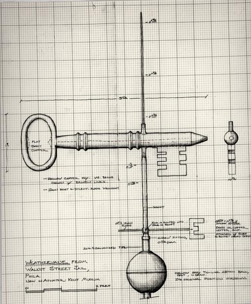 Figure 189
Weather vane from the Walnut Street Jail, Philadelphia. Drawing by Edward A. Chappell.
221
steeple by Robert Smith in Philadelphia, the compass and rule on Carpenters' Hall by Smith (Fig. 190), and the Viking helmet on Old Swedes' Church. By far though, it was the flat, banneret vane that reigned over colonial America. Predominately, weather vanes were used on public buildings such as churches, courthouses, schools, jails and prisons, state houses and market houses. Weather vanes did grace domestic structures such as the Governor Palace in Williamsburg, Mount Vernon, and Mulberry in South Carolina, but generally they denoted a public function.
WILLIAMSBURG WEATHER VANES
Weather vanes in Colonial Williamsburg today represent a design range spanning the entire eighteenth century. Examples include vanes at the Wren Building, 1695 (Fig. 191); the Capitol, 1700 (Fig. 192); the Palace, 1706-20 (Fig. 193); the Windmill, 1721; Bruton Church tower, 1769 (Fig. 194); and the Courthouse, 1770 (Fig. 195).2 Of these six, only the church and the Courthouse vanes are original. Bruton Church tower is topped with a banneret vane pierced with the initials "BP" and a simple scroll design on the spindle. The crudeness of the design and execution suggests that it may have been made locally. That the Courthouse vane may have been made by the same person is suggested by its similar design. Pre-fire photographs of the Courthouse show an additional piece of scrollwork between the compass arms and the banneret. There is perhaps one more segment of an original vane in town. The rod and scrollwork on the
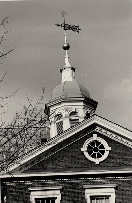 Figure 190
Original weather vane, Carpenters' Hall, Philadelphia. (CWF 83-1670, EAC)
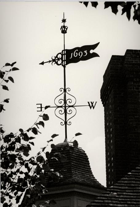 Figure 191
Wren Building weather vane, College of William and Mary. (CWF 81-FD-2854s)
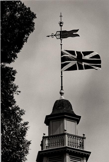 Figure 192
Capitol weather vane. (CWF 81-FD-2856s)
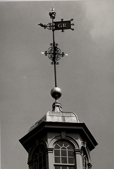 Figure 193
Governor's Palace weather vane. (CWF 81-FD-2858s)
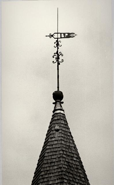 Figure 194
Original weather vane, Bruton Parish Church, ca. 1769. (CWF 81-FD-2853s)
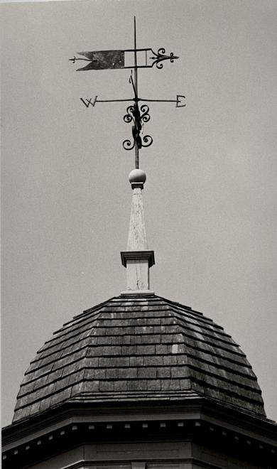 Figure 195
Original weather vane, Courthouse of 1770. (CWF 81-FD-2859s)
222
Powder Magazine's finial may have carried a banneret, as the stepped-down treatment of the spindle indicates (Fig. 196). Considering the building's function, this top piece might also have served the lightning conductor that was on the building; many weather vanes provided this secondary function for public buildings.
PHILADELPHIA AND ROBERT SMITH EXAMPLES
Banneret vanes in Philadelphia during the last half of the eighteenth century reflect a basic design conformity with contemporary vanes in Williamsburg and throughout America. A sampling of Philadelphia vanes ranging in date from 1747 to 1804 shows that the standard design on public buildings consisted of a pinnacle, ball, shaft or spindle, and banneret vane: Old City Hall, ca. 1747; Christ Church, 1752-54 (Fig. 9); Pennsylvania Hospital, East Wing, 1755-57 (Fig. 173); Carpenter's Hall, 177074 (Figs. 14, 191); Walnut Street Jail, 1773-77 Figs. 15, 190); Pennsylvania Hospital, West Wing 1793-96 (Fig. 174); and the Market House, 1804. The basic design was supplemented on different vanes with scrollwork, compass points, and symbolic or decorative motifs.
Robert Smith's work featuring weather vanes included: Second Presbyterian Church, 1749; Christ Church 1752; Nassau Hall, Princeton 1753 (Fig. 13); St. Peter's Church, 1759 (Fig. 10); and the Walnut Street Jail, 1773. The most accurate
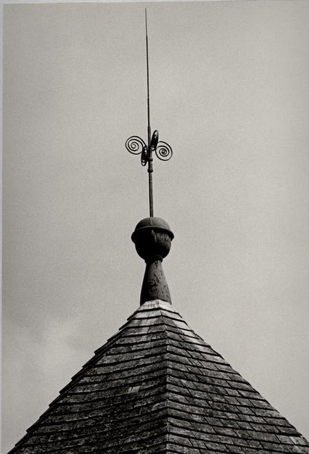 Figure 196
Original weather vane on the Magazine, parts missing. (CWF 81-FD-2855s)
223
representation of these vanes comes, of course, from those that are extant: Christ Church and Carpenters' Hall.
DOCUMENTATION
Robert Smith's written description did not mention the weather vane, or, for that matter, the cupola. However, it is highly likely that his drawings depicted these elements. Nor is the weather vane mentioned in Benjamin Powell's contract, which excluded "such other things as are usually important from England." We do know that the weather vane was one such item ordered from England by hospital director William Nelson. Details of Nelson's initial invoice are unknown. Did he enclose a detailed written description, a drawing or perhaps a reference to a well known existing English vane? Nelson's accompanying cover letter to London merchant Robert Cary dated January 21, 1771 sheds little light on the order:
The Legislature of this Colony having voted money to erect an Hospital for the Reception and maintenance of Ideots & Lunaticks, I have promised the Gentlemen, who are to direct the Building to procure such Materials, as will be wanted from England; I therefore desire that you send the several Articles mention'd in the inclosed Invoice, by the first ship, observing to insure them, & to place them to the Account of
Your most hble Servt.
Wm. Nelson3
It is in three subsequent letters from Nelson to Cary where specific reference is made to the vane:
September 5, 1771
224The Invoice of the Cross, vane & ca amounting to E 27.14..- which is received & I credit you for it in Account, but the Builder says, that it is most extravagantly dear, & that he had one made here nearly as Good for E 2 our Currency, tho's the spindle is not turned, as this is; and therefore, if no Abatement is made, I shall think they take a very unfair Advantage of Charging what they please for their goods.4
November 21, 1771
I hope you will try to get some Allowance for the Excessive Charge of the Weather Cock, which I complain'd of before or I shall think hardly dealt by.5
February 21, 1771
I observe the Reasons, which Mr. Millington gives for the high price of the Vane & Ca. which I suppose I must be satisfied with tho not convinced that it was not too Dear.6
By reference, these letters manage to provide important bits of information regarding the design of the hospital vane. The word "Cross" in the letter of September 5, 1771 indicates the common use of crossed directional arms of the compass points. The reference to a "turned" spindle indicates that the main vertical shaft for the vane assembly or part of it, was lathe-turned. The word "Weather Cock" in the letter of November 21, 1771 refers to the whole vane, being a misnomer stemming from the once common symbolic cock vanes on church steeples. The words weather vane and weathercock became synonymous.
Nelson's reference to a local vane is also important. The "nearly as Good" local vane costing £12 would be a good basis for a comparative analysis if it was known to which vane Benjamin Powell referred. Due to the limited number of vanes in 225 Williamsburg, especially those made in 1770, it can be surmised that the vane in question was either on Bruton Church or the Courthouse. Powell built the church tower in 1769. It is not known who built the Courthouse or the origin of its vane, but this may be the more likely vane referred to because of its superior quality as compared to the very simple Bruton vane.7
On December 30, 1771 the Treasurer's office paid William Nelson £188.13.9 for "Materials imported by him for the Hospital"8 This undoubtedly included the "too Dear" payment for the vane.
Another possible written reference was made in 1817 when Thomas Sands and James Guthry repaired "2 sets moldings round the Cupelow next the boll."9 It is possible that the "boll" refers to that of the weather vane.
Pictorial documentation consists of the Galt drawing of 1829 (Fig. 42), the Millington and Ramn lithographs of 1840 and 1855 respectively and the ca. 1885 photograph of the south elevation.10 The Galt drawing best illustrates the vane, although the details cannot be clearly distinguished. It does confirm the sequence from bottom to top of a ball, compass points, scrollwork, banneret vane, and a small decorative or symbolic piece near the top of the spindle.
The other illustrations cannot be used because there is no evidence that the original vane was reused for the new Greek Revival cupola in 1840. The Millington lithograph (Fig. 55) shows a banneret vane on a spindle without any other parts and 226 the Ramn lithograph (Fig. 56) shows compass points below a banneret vane. The vane in the Millington illustration, at least, looks suspiciously like a nineteenth-century work. A clear print of the ca. 1885 photograph (Fig. 68) faintly shows the widely spaced east-west compass arms.
DESIGN
All of the various elements of the hospital's weather vane were documented through the Nelson letters or the Galt drawing. For details, however, extant and documented English and American eighteenth-century vanes were researched. Throughout the entire design process the foremost considerations were proper scale, complexity of design and the relationship of the design to the Galt drawing vane.
The earliest weather vane design considerations emerged as part of the cupola studies. In a comparative analysis of cupola designs the vane was first drawn at comparative scales; 9' 3" (from bottom of ball to top of spindle), 9' 10" (based on Carpenters' Hall) and 13' 9" (based on the Galt drawing.)11 Comparative weather vane dimensions, in some cases based on scaled illustrations, were: Nassau Hall 12'; East Wing of Pennsylvania Hospital 13'; Carpenters' Hall 9' 6"; the Williamsburg Courthouse 9' 6"; and the Walnut Street Jail 8'.
During the last few months of 1981, research was conducted to determine the general history of weather vanes and the most appropriate design characteristics for an English vane
227
made in 1771.12 Based on this research a number of designs were considered for the banneret, scrolls, compass arms and decorative top piece (Fig. 197). The designs consisted of English, American, and local prototypes combined in a number of ways. The first preliminary designs were based on three theses: a Robert Smith influenced design that relied on Philadelphia banneret prototypes and English scrollwork; a completely English design; and the somewhat literal visual interpretation of the Galt drawing vane. A large part of the design review discussion centered on an interpretation of the Galt drawing and whether its depicted vane was pointing left or right. This was finally interpreted as a left orientation with a tail section longer than the front section. A banneret adapted from the St. Martin-in-the-Fields vane with a tail arrow from Congress Hall was first suggested in combination with scrollwork from Christ Church, Shrewsbury and a decorative top piece from Independence Hall (Fig. 198). This first tentative design had the cut out date 1770 on the banneret and a composition that placed the scrollwork closer to the ball rather than the banneret. The St. Martin design featured a front with two scrolls flanking an arrow point, a form common to both English and American examples, but one that varied greatly in execution. By using a prototype such as St. Martin's the vane takes on a more highly crafted appearance when compared to the Church or Courthouse vanes. Because the Galt drawing seemed to indicate a single rather than swallowtail rear, the St. Martin example provided a new distinctive type of
 Figure 197
Early studies for the Public Hospital weather vane. Drawings by James F. Waite.
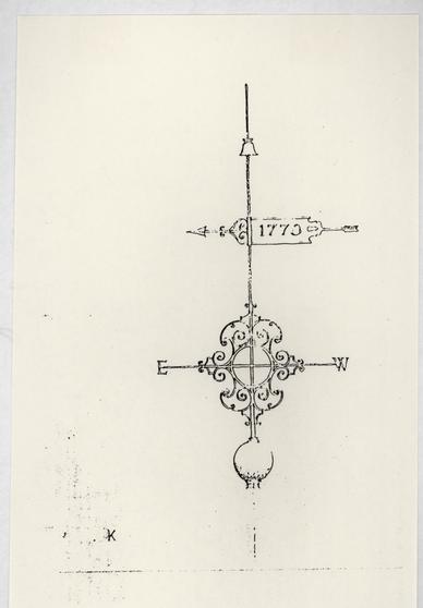 Figure 198
Interim design for the Public Hospital weather vane. Drawing by James F. Waite.
228
banneret vane in Williamsburg. The addition of an arrow tail was a concession to the interpreted Galt drawing and to what seemed to be basically an American element. A tail that protrudes from either a single or double pointed flag seems to be an American contribution to weather vanes. Because the specifications for the hospital vane are unknown, this detail acknowledges the possible American influence on the English product. Robert Smith's drawings just might have been detailed enough to depict a specific type of vane.
Further studies of scrolls prompted a design loosely based on the overthrow of the gate at Westover. A discussion of this study led to a careful examination and reinterpretation of the scrolls in the Galt drawing. The conclusion was that individual scroll pieces could actually be fairly simple, but seen together as an eight piece combination, the whole mass takes on a more complex form, as likely seen in the Galt drawing. Reacting against the past propensity to "over design" details in the Historic Area, the committee studied Ed Chappell's survey of weather vane scrollwork, especially the simple design of "C" scrolls much like those on the Stanwell Church, Middlesex, 1756.13 The committee debated the fact that the cost of the original vane had been considered "too Dear" and also the reference that the builder referred to a local vane that was "nearly as Good." While the builder's claim might be taken as a protest ploy, it could not be overlooked.
229A number of additional changes to the design were proposed in March 1982, but due to more urgent research considerations the weather vane design entered a two year hiatus. During this period, however, two significant events occurred that ultimately affected the design. In October 1982 painter's scaffolding on the Courthouse of 1770 allowed members of the Architectural Research Department and blacksmith Peter Ross to closely examine the weathervane, taking measurements and photographs. At about this same time, the Director of Engineering at Colonial Williamsburg determined that the Public Hospital and Wallace Gallery were in a moderate to severe category of risk assessment regarding loss due to lightning.14 Once this assessment was determined and a lightning protection system recommended, the Design Review Committee was faced with two alternatives regarding an NFPA approved system: numerous 12" conductor points all over the hospital and Gallery or one "Preventor" unit that would be attached to the weather vane, which would protect both buildings. Given the choice of two evils the radioactive "Preventor" system was chosen for reasons of cost as well as visual considerations. It was reasoned that, if the top point of the saucer-shaped "Preventor" unit could be extended, it might take the place of the decorative top piece of the vane ensemble. The manufacturer agreed to extend the unit's 9" point to 18" and to paint the bottom of the unit.15 Even though the reconstructed lightning conductor had been designed by this time, it would not satisfy the engineers or project 230 director, especially since it only protected the hospital. Perhaps more importantly, it was determined that the reconstructed eighteenth-century conductor running down the exterior of the building from the weather vane would not interfere with the "Preventor" unit that was grounded through the structural steel of the building.
Research and design discussions began again in April 1984. The committee met in early May and reviewed the previous design along with new considerations. Peter Ross informed the committee that he interpreted "turned spindle" to mean lathe-turned rather than twisted. This interpretation was reviewed and ultimately the detail was changed. The previously selected St. Martin banneret was again confirmed as a proper prototype with a slight elongation of its tail. The committee reinterpreted the Galt drawing and decided on an arrow point for the rear as well as the front (Fig. 199). The arbitrary use of a building date on the banneret was deleted due to the widespread use of such dates on colonial revival vanes and on the lack of documentation for its inclusion. Picking up where it had left off, the committee reviewed the complexity of scrollwork based on a number of English weather vanes photographed by Carl Lounsbury during his courthouse research trip and concluded that a simple "C" scroll would be appropriate.16
The committee met with Peter Ross on May 10 to review the first two sheets of full-scale detail drawings by James Waite. From this meeting came a number of construction detail
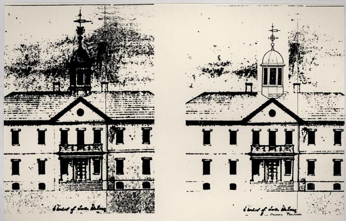 Figure 199
Comparison of the reconstructed vane, right, with the Galt drawing, left.
231
changes, many of which were based on details from the Courthouse of 1770 vane-17 Two additional meetings were necessary to refine the design before a final set of working drawings were produced. The location of the vane's various elements on the spindle and the its scale in combination with the cupola were major considerations. The following documentation from Edward Chappell and Travis McDonald referred to the final June 12, 1984 set of drawings:
Total Height
The vane in the Galt drawing was scaled by Jim Waite to be about 15' in height from the base of the ball to the tip. Comparison with most original vanes (e.g. the 9' Carpenter's Hall spindle and the 10' Christ Church spindle) indicates that the parts of the vane may have been consistently overscaled on the Galt drawing. In trying to proportion the overall height to the various parts, based on examples cited below and other vanes in our burgeoning vane file, we have established a dimension of 10' 10".
Placement
The relative spacing and location of the components are based on the Galt drawing; Christ Church, Shrewsbury; and the Pennsylvania Hospital's 1755 vane.
Banneret
The banneret itself is based on St. Martin-in-the-Fields, with the addition of a rear arrow intended to duplicate an arrow-like feature included on the Galt vane. Carpenters' Hall, Bruton, and the Courthouse of 1770 have rear arrows. A vertical bar just before the spindle was added for stability, based on similar banneret details at the "Old First" Church in Newark, New Jersey and Congress Hall, Philadelphia
The scrolls framing the front are taken from the St. Martin vane and are similar to those at Christ Church, Shrewsbury; Parkman Market, Boston; and the Old Town Hall, Newcastle, Delaware. The relationship of the arrow length to the scrolls is similar to Christ 232 Church, Shrewsbury and Reigate, Surry, but the rear arrow was lengthened to conform to the Galt drawing. The actual arrowhead shape was based on Carpenters' Hall, St. Martin and Stanwell Church, Middlesex. The smaller rear arrowhead is found at the Town Hall; Newcastle, Delaware and Congress Hall, Pennsylvania. The solid part of the vane is proportioned from the Galt drawing.
The scaled length of the banneret in the Galt drawing is about 8', which is most likely oversized. Although there are examples of relatively long bannerets, such as the Old City Hall vane, Philadelphia, 7' 2"; Independence Hall vane, 9'; and the Pennsylvania Hospital;'s 1755 banneret, about 7', a more commonly used size for a building the scale of the Hospital is about 5' 6". Most of our measurements are approximate, but Carpenters' Hall and the Old Swedes Church in Philadelphia are 5' 6"; the Moravian Church in Salem has a 5' banneret and the Town Hall in Newcastle has one 4' 6" in length. As a result, we have chosen 5' 6" for our banneret. The height was drawn by Jim Waite to be in proportion to its length, based on the examples cited above. Examples show that bannerets rest on both spindle shoulders and on flared collars; based on Bruton Church and the Courthouse of 1770, the former was adopted for the Hospital banneret.
Scrolls
Recently, there was committee consensus that the Galt drawing shows relatively simple c scrolls framing the directional arms. From most angles, this will result in a rather complex design. The scrolls of the Bruton Church and Courthouse vanes were the specific inspiration for the Hospital design; these are similar to those on Holy Trinity Church, Rudgwick, West Sussex. Scrolls are typically fastened by collars when more than two come together, as on the spindle, and riveted together when two come together, as on the arrow on the compass arms. Collars used in a similar manner are found at the Magazine, Holy Trinity Church, Rudgwick; the Town Hall at Yarm; and at the Town Hall at Reigate. It was decided to use a molded collar like the one on the Courthouse of 1770.
Letters
The best prototype for compass letters are those on the Courthouse of 1770, although reference has also been made to a wide range of serifed weather vane letters. The Courthouse letters are welded to the ends 233 of the compass arms. The shape of the letters and their proportionate size are also taken from the Courthouse example.
Compass Arms
These have been established at 1' 8" in length, measured from the spindle to the letter. This is based on the visual analysis of a relationship with the length of the vane and on the 1' 8" arms at Christ Church, Shrewsbury; the 1' 6" arms at the Courthouse of 1770; and the 1' 4" arms at the Parkman Market, Boston. The Courthouse of 1770 is the prototype for the details of these arms, with the exception of the mortised wedge above the arms, which is not needed since the upper scrolls will secure the arms to the spindle.
Ball
The size of the ball has been set at 15" in diameter based on a comparison of balls on similarly scaled buildings. Carpenters' Hall and the Old Town Hall have 16" balls while Christ Church, Shrewsbury has a 13" ball. Based on the proportions of the Galt drawing ball (scaled at 20"), the 15" size seemed to work the best. The ball from the Walnut Street Jail measured 12", while that at Mt. Holly, New Jersey, Courthouse was 20". The center seam construction of the ball was based on recent detailed photographs of the Christ Church ball. This prototype was not used in its entirety, however. The Christ Church ball was basically made in four pieces, having large top and bottom plates (similar to the Moravian Church's vane). To reproduce all these parts seemed unwise due to the potential of water problems. A small square cover plate, based on the ghost of one seen on the Christ Church vane, was designed to protect the top of the ball. A flanged bottom was designed to that the ball fit down on the cupola's wooden pinnacle.
Miscellaneous Details
The reference to a "turned spindle" is interpreted by Peter Ross to mean a lathe-turned detail rather than a twisted configuration.18
As a final aspect of the design the committee considered alternative schemes to mitigate the inappropriate shape of the lightning "Preventor" unit atop the vane. The 234 committee reviewed selected eighteenth-century weather vane dodads that lent themselves to a position below the device (Fig. 200). A simple spread scroll piece from the Germantown Academy, 1760, was selected and drawn full-scale to accompany the working drawings set.
CONSTRUCTION
Construction of a full scale weather vane mock-up constituted the first step in the construction phase. Earlier mock-ups in brick, mortar and shingles had shown themselves to be well worth their trouble. A weather vane mock-up was considered especially important not only because of the great amount of anticipated labor on the part of the blacksmiths but also to judge its scale in combination with the building. The vane looked fine in drawings but actually viewing it on the building was considered crucial before work began.
The weather vane mock-up placed on the hospital cupola on June 6, 1983 succeeded in confirming a compatible and proper scale (Figs. 201 - 203). This foamcore and bamboo vane was so successful, in fact, that it remained on the building for about one month, faithfully turning in the wind until it was dismantled.19 The committee hesitantly concurred that the addition of scrolls to the "Preventor" greatly enhanced its form.
Eighteenth-century weather vanes were commonly constructed of two materials: wrought iron and copper. Presumably a more expensive and well-made vane would be composed
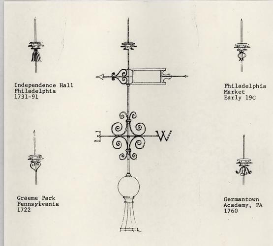 Figure 200
Various designs considered for the "Preventor" unit on the Public Hospital weather vane.
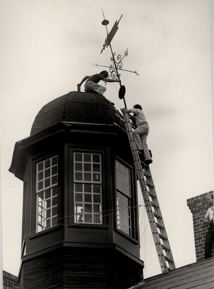 Figure 201
Installation of the weather vane mock-up. Travis C. McDonald (left) and Willie Graham (right). (CWF 84-EAC-2370-22)
 Figure 202
Repair of the weather vane mock-up. Edward A. Chappell (left) and Travis C. McDonald (right). (CWF 84-SH-2372, 30s)
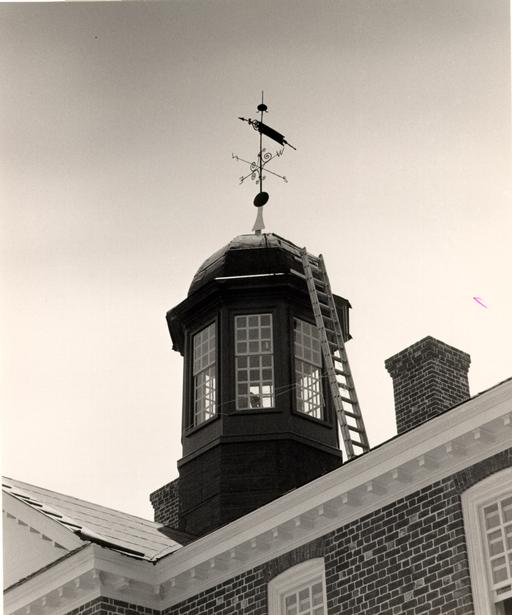 Figure 203
Weather vane mock-up in place. (CWF 84-TCM-2609-26)
235
of both materials while a less expensive one might be entirely of iron. Wrought iron elements would include the spindle, scrolls, compass arms and, perhaps, the decorative top piece. Copper was generally used for the ball, compass letters and banneret. These latter elements in copper and the top piece were the parts frequently specified to be covered in gold leaf. It is entirely likely that the original hospital vane was composed of some copper parts and that those parts were gilded to catch the rays of the sun. Most English weather vanes of the seventeenth and eighteenth centuries were made with "flags" or vanes of "gilt copper." J. Starkie Gardner documents a number of these in his book, English Ironwork of the XVIIth and XVIIIth Centuries. American weather vanes, of a local or imported origin, were also frequently composed of wrought iron and copper. In Boston, Shem Drowne made a number of copper vanes: Christ Church, 1740; Faneuil Hall, 1749; and a "cock gilt in the best manner" in 1771. Certainly, many vanes made in America were entirely of iron but J. Rayner Whipple in "Old New England Weather Vanes," characterized the majority of New England's vanes as "copper covered with gold leaf." At least three buildings by Robert Smith in Philadelphia also bore copper and iron vanes. In the 1758 building specifications for St. Peter's Church, Smith specified a vane 'composed of copper to be neatly gilt' to top off the cupola. Christ Church had a copper and iron vane, and a contemporary description of the Walnut Street Jail vane in Teeter's Cradle of the Penitentiary mentions that its vane was
236
gilded. An additional reference to paint colors is found in a letter from Robert Smith in 1771 in which he specified that the weather vane spindle on Christ Church be painted "Black of a dark couler."
Despite this evidence, however, the hospital vane was constructed entirely of wrought iron with the exception of the ball. In large part this was a practical decision to avoid a possible electrolytic reaction between copper and iron that would accelerate the corrosion of copper. Both original local vanes provided precedent for an all iron vane.
Construction of the weather vane took place at the Deane Forge blacksmith shop and at the Golden Ball shop. At the former location master blacksmith Peter Ross and four assistant smiths fashioned the spindle, scrolls, compass arms and letters, banneret and top scrolls (Figs. 204 - 208).20 Master silversmith James Curtis and his assistant hammered the two-piece 15" copper ball out of flat copper plate at the Golden Ball (Fig. 209).21 Both groups of craftsmen were deferred to on a number of construction details. For instance, the blacksmiths recommended collars rather than rivets to hold the scrolls on the spindle, based on the Courthouse vane example (Figs. 210 - 211). They also recommended a gradually tapered spindle (2" to 1 ¼") rather than a stepped-down detail and the riveted plate method of forming the banneret (Fig. 212). The serified letters indicating the compass points were based on the iron examples on the Courthouse vane. Rather than securing the cross arms to the
 Figure 204
Peter Ross attaching a cardinal directional arm to the weather vane. (CWF 85-TCM-339-8) (Photo 1984)
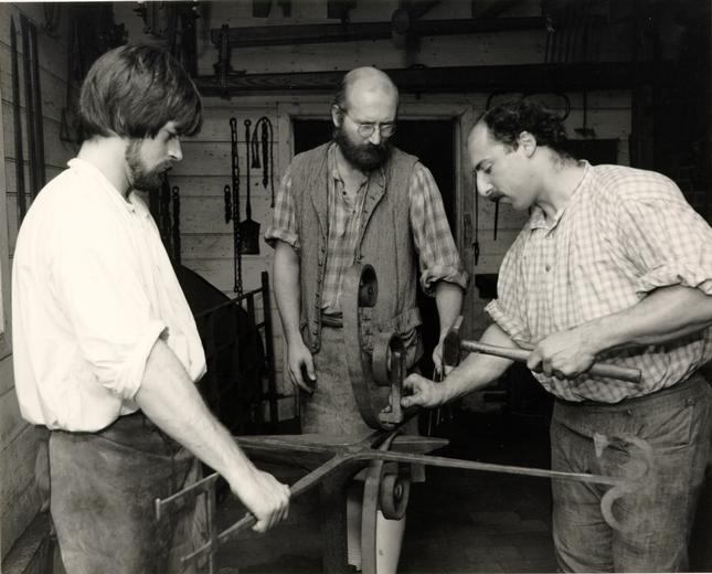 Figure 205
Ken Swartz, Rick Guthrie and Peter Ross attach the scrolls to the vane's cross arms by rivets. (CWF 1984)
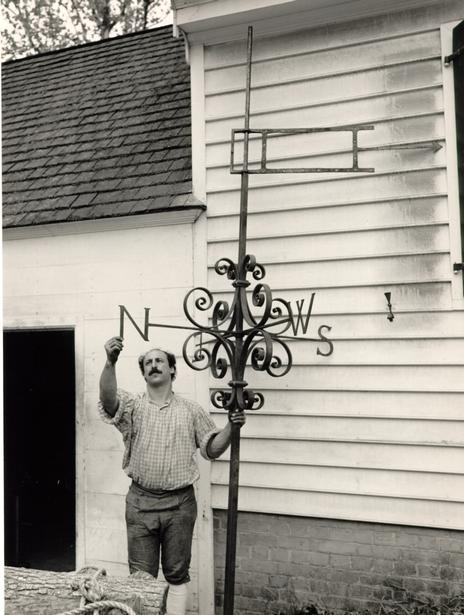 Figure 206
Peter Ross examines partially completed vane. (CWF 85-TCM) (Photo 1984)
 Figure 207
Detail of incomplete bannerett. (CWF 85-TCM-342-18) (Photo 1984)
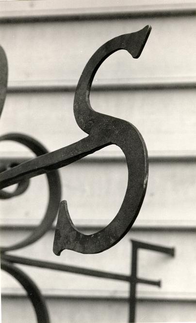 Figure 208
Detail of Cardinal letter prior to painting and gold leaf. (CWF 85-TCM-342-5) (Photo 1984)
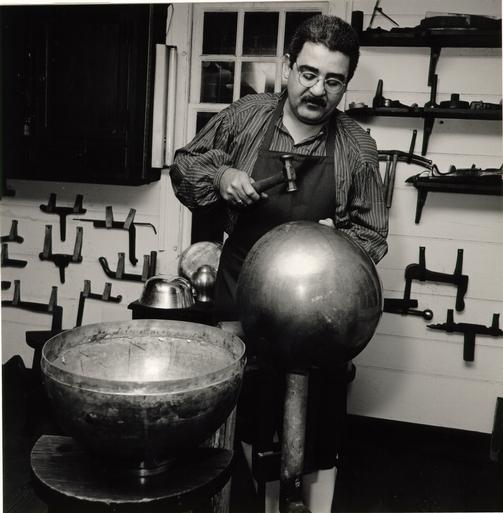 Figure 209
Silversmith James Curtis fashions the two halves of a sphere from flat sheets of copper. (CWF 84-FD-2247)
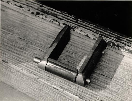 Figure 210
Detail of collar which fastens the scrolls to the spindle. (CWF 85-TCM-343-28A) (Photo 1984)
 Figure 211
Detail of the scrolls and their attachment to the spindle. (CWF 85-TCM-342-10) (Photo 1984)
 Figure 212
Detail of bannerett. (CWF 85-TCM-342-15) (Photo 1984)
237
spindle with mortised wedge as in the Courthouse example, the wedge was omitted in favor of having the scrolls hold the arms in place.
one of the most difficult aspects of constructing the vane was that of balancing the banneret (Fig. 213). To turn freely in the wind the front and rear portions of the banneret must be perfectly balanced at the point of intersection with the spindle. When the plate was riveted to the tail section an imbalance in favor of the rear occurred. The most convenient solution was to thicken the front arrowhead since it needed to be remade in a more sharply pointed form. Apparently, this solution was not a new one, based on the obvious additions to the arrow points of the Home Moravian Church and Independence Hall vanes. The large scrolls affixed to the arrows of the Bruton Church and Courthouse of 1770 vanes might easily have been added for this same practical reason. This solution worked to an extent but it did not completely balance the banneret. Ultimately, the front shaft was lengthened about two inches in order to create the necessary balance (Fig. 214).
After completion of the spindle but prior to the vane assembly, the spindle was taken to the production blacksmith shop where its end was threaded to receive the "Preventor" unit.22 The completed copper ball had also been sent to the sheet metal shop to receive its bottom flange.23 With the spindle back at the Deane Forge, the scrolls and compass arms were attached and
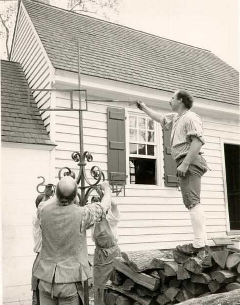 Figure 213
Peter Ross checks the balance of the partially completed bannerett. (CWF-85-TCM) (Photo 1984)
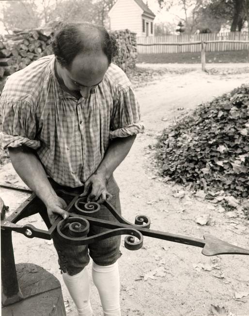 Figure 214
Peter Ross rivets front scrolls to bannerett. (CWF-85-TCM) (Photo 1984)
238
the vane then transported via horsecart to the paint shop to be painted and gilded (Fig. 215 - 217).24
The completed weather vane was considered so outstanding that it went on public display in the Courthouse of 1770 for one week prior to its installation on December 5th.25 On that snowy morning at 10:00 a.m. the vane left the Courthouse by horsecart for its trip to the hospital (Fig. 218). An installation ceremony developed around the tradition of placing objects in a weather vane's ball (Fig. 219). This tradition is an ancient one, documented as early as the thirteenth century where at the Cathedral of St. Paul's in Jordan the weather vane's ball "was filled with relics of saints destined to protect it from storms, and these were examined and renewed from time to time with much ceremony."26 more relevant example comes from Faneuil Hall in Boston. The famous grasshopper vane by Shem Drowne suffered several mishaps, including a fall caused by the 1755 earthquake and another fall in 1889. During one of the repairs related to these accidents, the grasshopper was found to have a "vest pocket" in which was found a paper with the following history:
Shem Drowne made it May 25, 1742. To my brethren and fellow Grasshopper: Fell in ye year 1753 Nov. 18, early in ye morning by a great earthquake by my old Master above … Again Like to have met with my Utter Ruin by fire, but hopping timely from my Public Situation came of with Broken bones and much Bruised Cured and fixed . . (by) Old Master's son Thomas Drowne June 28, 1768, and though I will promise to Discharge my Office, yet I shall vary as yet wind.27
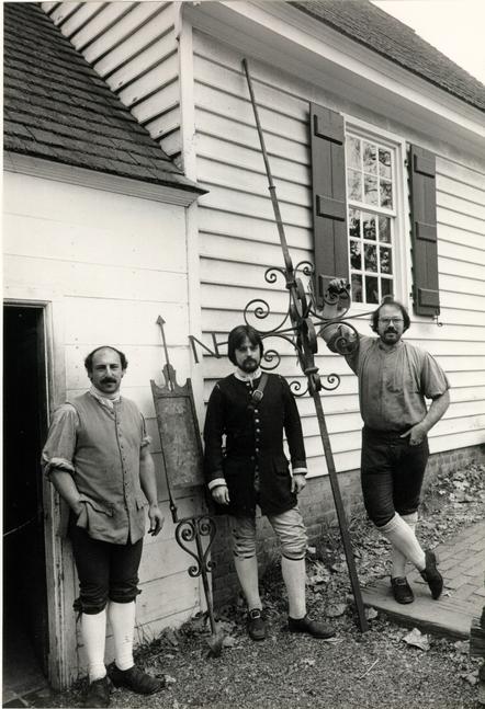 Figure 215
Peter Ross, Kenneth Swartz and David Harvey stand near the completed vane. (CWF 85-TCM-342-23) (photo 1984)
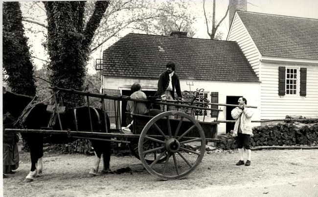 Figure 216
The completed vane is loaded onto a horse cart for a trip to the paint shop. (CWF TCM-341-13)
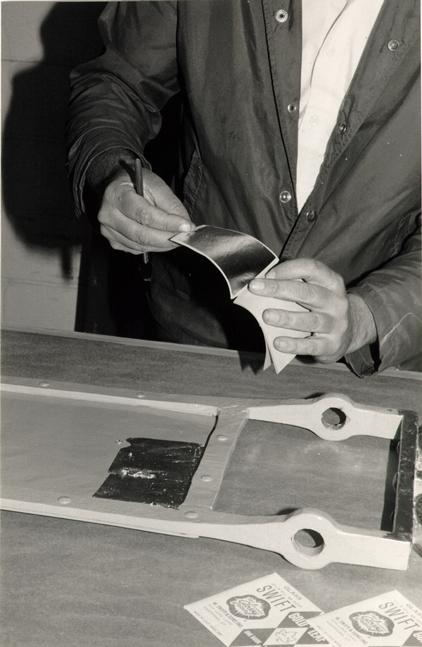 Figure 217
At the paint shop gold leaf is applied to the bannerett. (CWF 84-TCM-2614-34A)
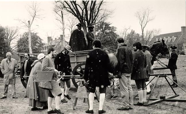 Figure 218
The weather vane arrives at the Public Hospital site for installation. (84-FD-2625-2A)
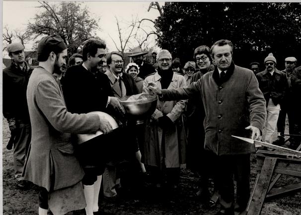 Figure 219
Robert C. Birney places commemorative objects in the weather vane ball. George Cloyed and James Curtis hold the ball while Travis McDonald, Nicholas Pappas and Beatrix Rumford look on. (CWF 84-FD-2655-16)
Concerning another eighteenth-century Boston landmark, Christ Church, Reverend William Croswell recorded in his diary in 1834 when the vane was repaired that he "wrote something to put in the ball of the steeple, arranged in the shape of a cross."28 The same steeple and vane were repaired in 1934. At that time, "a sodden mass of papers," thought to date from an 1847 repair, were removed from the ball and new documents were once again sealed in the ball.29
Although there is no documentation that objects were originally placed in the Public Hospital weather vane ball, or in any other Williamsburg vane for that matter, the tradition of doing so presented an opportunity to celebrate the most ornamental feature of the building. Into the spherical capsule were placed two engraved copper plates: one with the names of those responsible for the design and manufacture of the vane and one with a short history of the original and the reconstructed building.30 In the place of "saint's relics" were substituted fragments of the original hospital's brick and mortar. Other items included photographs of the weather vane during fabrication; photographs of the hospital under construction; articles referring to the reconstruction project; 1984 coins; and a 1/3 scale heart cypress shingle signed by the four shingle makers. And finally, into this "cornerstone" of sorts went two sheets of paper filled with the signature of all those employees, workers and bystanders who witnessed the installation.
240Preparations were made of the weather vane on the ground before a crane lifted it to the cupola (Figs. 220 - 222). This included slipping a teflon washer onto the spindle and applying a liberal amount of grease to help the banneret fulfill its purpose. Around section of pipe with a 2" diameter was placed on the bottom of the square spindle in order to help the spindle fit tightly inside of its square tube receptacle on the cupola (Fig. 223). Two holes had already been drilled in the spindle and when it had been lifted into place it was bolted onto the cupola tube. Later, when the contractor was asked to adjust the alignment of the vane to match the axis orientation of the building, the spindle bolts were taken out altogether and the spindle/pipe sleeve were welded to the cupola tube.31 The copper ball had been slipped on the spindle with its top wrought iron cover cap and attached to the upper part of the wooden pinnacle. The complete pinnacle was not in place, however, due to millwork fabrication problems, which prevented the final placement of the ball.32 When the corrected pinnacle was finally placed on the cupola it was screwed together around the steel tube in two halves. The wrought iron cap that protects the top hole of the ball was secured solely by caulking. As a final measure of preparation and to take advantage of the cupola scaffolding, painters touched up the paint and gilding on the vane (Figs. 224 - 226).33
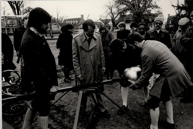 Figure 220
James Curtis and George Cloyed fit the ball on the spindle as Ken Swartz and Travis McDonald look on. (CWF 84-FD-2655-17)
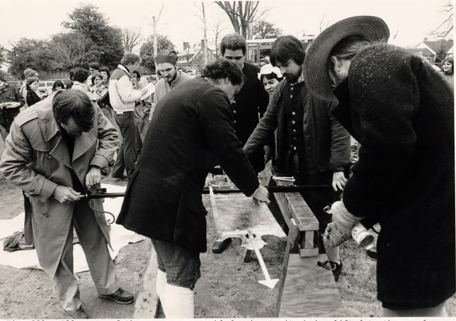 Figure 221
All parts of the vane are assembled prior to its being lifted to the cupola. (CWF 84-FD-2655-4)
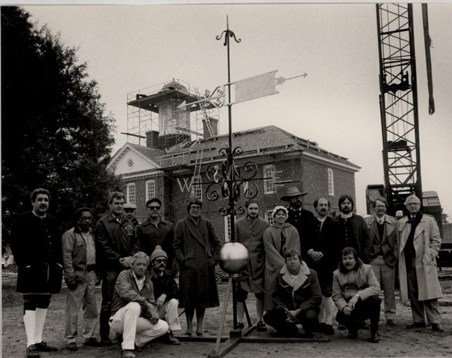 Figure 222
Group photograph of craftsmen and others who worked on the vane. (CWF 84-FD)
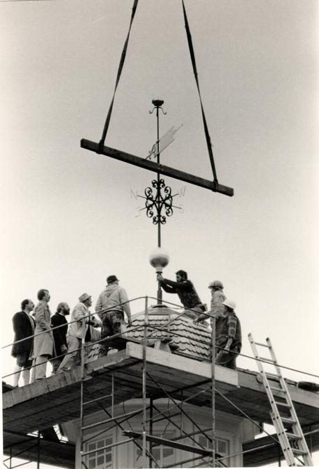 Figure 223
A crane lifts the weather vane onto the cupola. (CWF 84-Fd-2656-16A)
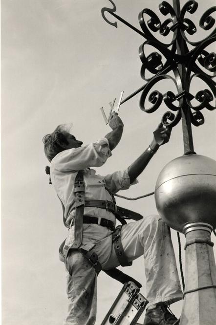 Figure 224
A painter reapplies gold leaf to the weather vane after its installation. (CWF 85-TCM-42-29A)
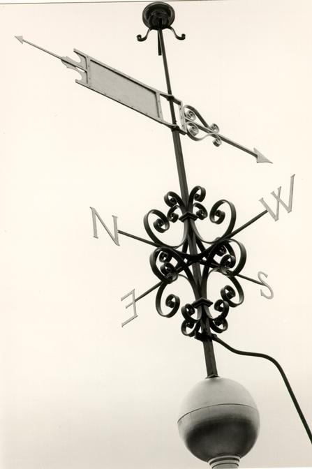 Figure 225
The completed weather vane in place with its lightning conductor attachment. (CWF 85-TCM-41, 34s)
 Figure 226
Public Hospital weather vane. (CWF 85 TCM-327-34a)
CHAPTER XXVI
NOTES
The Capitol vane is very similar to that on the Wren Building. Again, it would have been an important piece because of its design and workmanship and would have represented a good English banneret vane of ca. 1700. The absence of scrollwork beneath the banneret is appropriate for the time. Like the Wren Building's vane, a symbolic crown tops the spindle and the letters "A R" incorporated into the banneret represent the reigning monarch, Queen Anne (reigned 1702-1714).
The Governor's Palace vane is a good design for the time represented, ca. 1720, and for the type of building. The design of the vane is very appropriate. It is a transitional form between the earlier banner type and the later banneret type. The "flag" part of the vane is very traditional, taking the form of the early tail-less banners. The attached fleur-de-lis traditionally represented the monarch's standard. In addition, the "G R" pierced in the vane is meant to represent the reigning monarch, George I (reigned 1714-1727), and the symbolic crown above represents a royal building. The combination of the 242 forward scrolled pointed, with the obviously separate banner to the rear, provides a transitional character to the whole vane appropriate for the time. The elaborate scrollwork is fancy for the period but also appropriate considering that it was the royal governor's residence. The vane is meant to represent the latter part of the construction, ca. 1714-1720, because of the reference to King George.
The vane on Robertson's Windmill is very appropriate for its 1721 date. Not only is the simple, locally made form in keeping with the type of structure and period, but is literally based on a surviving Pennsylvania vane of 1699. The likelihood that such a vane existed on Robertson's Windmill is remote.
The actual designs of reproduced vanes used in Williamsburg were literally based on contemporary prototypes in some instances and loosely based on a number of prototypes in others. Two early books that might have helped as reference works are J. Starkie Gardner's English Ironwork of the XVIIth and XVIIIth Centuries, published in 1911, and Albert Sonn's Early American Wrought Iron, published in 1928. Famous American vanes might have been seen in situ, such as the four identical vanes at Mulberry Castle at Oakley, South Carolina, but their publication in books like Sonn's provided easy references and prototypes. There is little doubt that Mulberry Castle's 1714 vanes, pictured in Plate 243 of Sonn, was used as the prototype for the Governor's Palace. There is also little doubt that the Chester Creek Mill vane of 1699, pictured in Plate 242 of Sonn, was used as the prototype for Robertson's Windmill. Other designs could be a combination of prototypes shown in a book like Gardner's. For example, the Capitol vane could be a combination of the "flag" section of the Greenwich Hospital vane, shown in Fig. 155 of Gardner, and the "pointer" from the Minister at Sheppey, shown in Fig. 161 of Gardner. This imaginative combination of elements would have produced unique designs in the spirit of original seventeenth and eighteenth century vanes.
PLATE ONE
The Public Hospital was constructed in 1771-1773 after designs by Robert Smith of Philadelphia. It was built by contractor Benjamin Powell and bricklayer Samuel Spurr of Williamsburg. Afire in 1885 destroyed the building.
Reconstruction of the building took place between 1981 245 and 1985. Designed by the Public Hospital Design Review Committee (CWF) with the firm of Roche Dinkeloo and Associates. Construction by the R. E. Lee Company and the Colonial Williamsburg Foundation.
PLATE TWO
This weather vane constructed in 1984 and erected on December 5, 1984.
Public Hospital Design Review Committee
- Edward A. Chappell
- Travis C. McDonald
- Nicholas A. Pappas
- Beatrix T. Rumford
- James F. Waite
Blacksmiths
- Richard Guthrie
- David Harvey
- Marget Kellam
- Peter M. Ross
- Kenneth Schwartz
Silversmiths
- George Cloyed
- James A. Curtis
Painters/Gilders
- Joe Camacho
- John Hickman
- W. D. McClassister
- Phillip Moore
Others
- Bernie Bilenki
- Arnold Campbell
- Willie Graham
- Robert Ward
CHAPTER XXVII
LIGHTNING CONDUCTOR
DESCRIPTION
The Public Hospital lightning conductor is a ¾" diameter wrought iron rod that extends in two linked sections from the weather vane to the ground. It is clamped to the weather vane and attached by wrought iron hooks to the cupola, roof, and brick wall. A short separate link connects the conductor to a wrought iron ground below grade.
DOCUMENTATION
While re-excavating the original foundations in September, 1982 to examine brick colors, the hospital's eighteenth-century lightning conductor ground was discovered (Fig. 227). Observing what appeared to be a wrought iron rod with a hooked end near the south pavilion's west wall, Travis McDonald directed the archaeologists doing salvage work at the site to examine the piece.1 What they found was a hand wrought, Y-shaped iron bar lying horizontally in the ground with its widely spaced arms pointing away from the building toward the southwest (Figs. 228 - 229). One arm measured 4' 7 ½" x 1 ¼-½" x 1" with a round eye on the neck end and a round hook on the other. A 4' 0" piece of similar thickness and with a similar hook had been joined to this about 9" from the end to form the other arm. Attached through the hooks and driven into the
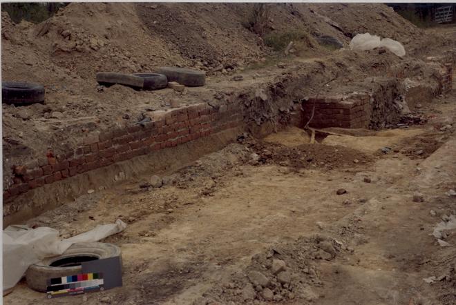 Figure 227
Public Hospital lightning conductor ground in-situ at west corner of south pavilion. (CWF 82-FD-750)
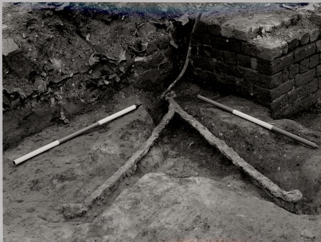 Figure 228
Public Hospital lightning conductor ground. West corner of south pavilion wall. (CWF 82-FD-4982)
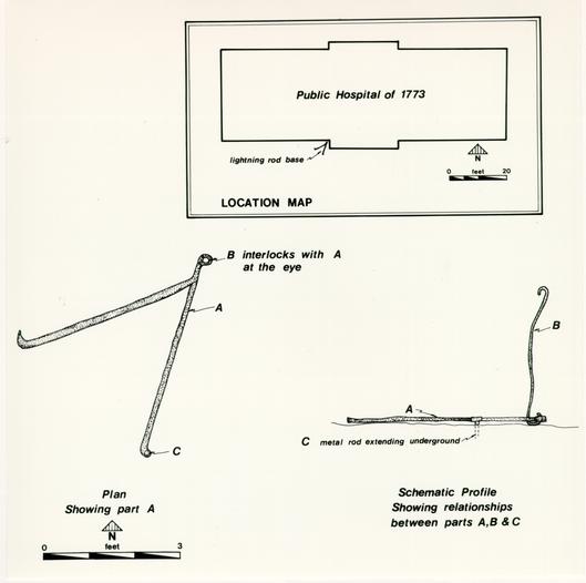 Figure 229
Public Hospital lightning conductor ground. (Drawing by Virginia Caldwell) (CWF #86-416)
248
ground, at a 90 degree angle, were two wrought iron spikes 3' 5 ½" long with flat 2 ½" long heads. Hooked onto the neck eye was a ¾" round line 3' long that would have extended slightly above grade where it, in turn, would have hooked onto the conductor (Fig. 230). Curiously, this piece was only partially excavated during the 1971-72 season and not documented in any way except that it appears in a photograph of the excavated foundations (Fig. 80).2
There are no reasons to suspect that a lightning conductor was not an original part of the building in 1773 or added shortly thereafter. The anchor spikes that had been driven into the clay subsoil indicate that the ground had not moved since installation. However, the principal evidence for this assertion is an account of blacksmith James Anderson in 1789. Among the repairs and work at the hospital recorded in Anderson's ledger for that year is the entry for taking down, altering and putting back up "the Conductors."3 original construction records do not survive, but the absence of any reference to a hospital conductor in Anderson's 1778-1785 ledger makes it very likely that the lightning conductor was placed on the building at its completion. Repairs to the conductor after a sixteen year period are also very likely. To substantiate that the ground was indeed an eighteenth-century form and to find further design evidence for the actual conductor, intensive research was conducted and presented to the Design Review Committee a month after the discovery.4 The committee enthusiastically endorsed a
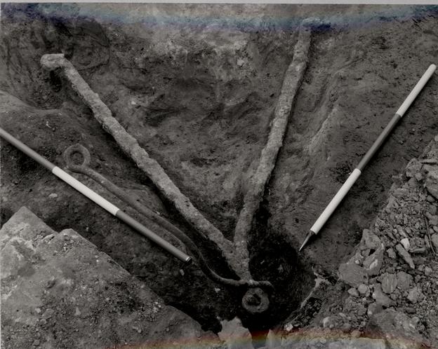 Figure 230
Public Hospital lightning conductor ground in-situ. (CWF 82-FD-4984)
249
reconstructed lightning conductor and approved an initial design.5 The lack of previous research on eighteenth-century conductors dictates that much of the research and analysis be included in this report by way of comparative examples.
The south elevation of the Public Hospital, photographed ca. 1884 (Fig. 69) shows a lightning conductor extending up the building from a point where the anchor was found. This conductor does not follow the roof line above the cornice and eaves, but makes a straight line for the cupola and vane. This is evidently a later conductor. It was probably common to replace conductors but to retain the anchors. If there was a connecting link the new conductor could be attached above grade. The conductor on the old photograph of the Courthouse makes a similar direct line to the cupola, a quick and easy way to put a replacement up. The Gibbs and Rowe report makes reference to a new conductor in 1877, but a careful reading of the reference leads to the conclusion that it was actually a downspout water conductor.
ORIGINS OF THE LIGHTNING CONDUCTOR
Benjamin Franklin began reaching conclusions based upon his experiments with electrical conductors in 1749. In the following year he published what would be the beginning of numerous discussions and recommendations based on his investigations.6 By 1752, Franklin had installed a lightning conductor on his own house and similar devices had been installed 250 on the Pennsylvania Statehouse and the Academy in Philadelphia.7 And, by 1753, Franklin's popular Poor Richard contained instructions for making and erecting lightning conductors.8 Soon Franklin began receiving correspondence from both Europe and America containing questions regarding the erection of conductors, horror stories of lightning striking unprotected houses and testimonials from grateful owners of protected houses. Franklin continued to perfect his invention, so that by 1767 he would offer the following instructions:
An iron rod being placed on the outside of a building, from the highest part continued down into the moist earth, in any direction strait or crooked, following the form of the roof or other parts of the building, will receive the lightning at its upper end, attracting it so as to prevent its striking any other part; and, affording it a good conveyance into the earth, will prevent its damaging any part of the building.
A small quantity of metal is found able to conduct a great quantity of this fluid. A wire no bigger than a goose quill, has been known to conduct (with safety to the building as far as the wire was continued) a quantity of lightning that did prodigious damage both above and below it; and probably larger rods are not necessary, tho' it is common in America, to make them of half an inch, some of three quarters, or an inch diameter.
The rod may be fastened to the wall, chimney, &c. with staples of iron. The lightning will not leave the rod (a good conductor) to pass into the wall (a bad conductor), through those staples. It would rather, if any were in the wall, pass out of it into the rod to get more readily by that conductor into the earth.
If the building be very large and extensive, two or more rods may be placed at different parts, for greater security.
It is therefore that we elevate the upper end of the rod six or eight feet above the highest part of the building, tapering it gradually to a fine sharp point, which is gilt to prevent its rusting.
251Thus the pointed rod either prevents a stroke from the cloud, or, if a stroke is made, conducts it to the earth with safety to the building.
The lower end of the rod should enter the earth so deep as to come at the moist part, perhaps two or three feet; and if bent when under the surface so as to go in a horizontal line six or eight feet from the wall, and then bent downwards three or four feet, it will prevent damage to any of the stone of the foundation . (…)9
Franklin spent a considerable amount of time in London in the 1760s and 1770s. We find him writing to John Winthrop from London in 1770 that "St. Paul's Church is now guarded agreeable to the Directions of a Committee of our Society; and many Gentlemen's Houses in the Villages around London are now furnished with Conductors."10 Winthrop replied to Franklin from Cambridge, Massachusetts the same year: "I am very glad to find your admirable invention of Lightning Rods is coming into fashion in England … . I have on all occasions encouraged them in this country, and have the satisfaction to find, that it has not been without effect. A little piece I inserted in our newspapers last summer induced the people of Waltham (a town a few miles from hence), to fix rods upon their steeple, which had just before been much shattered and set a fire by lightning. They are now becoming pretty common among us, and numbers of people seem convinced of their efficacy."11 The battle of erecting conductors seems to have been won in America faster than in Europe. Franklin wrote to a friend in 1772 that "Pointed Conductors to secure Buildings from Lightning have now been in use near 20 years in America, and are there become so common, 252 that numbers of them appear on private Houses in every Street of the principal Towns, besides those on Churches, Publick Buildings, Magazines of Powder, and Gentlemen's Seats in the Country. Here in England the Practice has made a slower Progress… ."12 Virginia, it seems, was no laggard in putting Franklin's invention into use.
EARLY CONDUCTORS IN VIRGINIA
The earliest account of conductors in Virginia is found in the Gentleman's Magazine (London) May, 1752, in which a letter from Maryland described a conductor, depicted a rod, and stated that "There is a person goes about Virginia, erecting machines…"13 Their acceptance must have been quick. The Reverend Andrew Burnaby, who travelled through Virginia in 1759, noted among other observations, the frequency of conductors and stated "I believe no country has more certainly proved the efficacy of electrical rods, than this… ."14 Other sources make reference to conductors, such as a Virginia Gazette notice in July, 1768, that would seem to indicate conductors were not widespread: "On Wednesday the 6th instant, about dusk . . . the house of Ryland Randolph, Esq. in Henrico was stuck with lightning:… (as the expense of an Electrical Machine is so trifling, it is suprising that they are not more general)."15 Yet, by the 1780s, two separate accounts from European travellers corroborate indications of widespread use of conductors. Chevalier D'Ancteville, commenting on Williamsburg in 1781, 253 remarked that "Upon nearly all the houses are lightning rods."16 A description of Virginia in 1783 by Johann David Schoepf states: "By reason of the numerous storms, which rage especially here and in North Carolina, but are little sparing of the entire coast of North America, and everywhere work great destruction, the people generally have spared neither cost nor trouble in protecting their houses by electric conductors, that beneficent discovery of the great Franklin. One fails to see them almost nowhere in the great towns or on the larger houses in the country."17
CONDUCTORS IN WILLIAMSBURG
There are eight extant lightning conductors in the Historic Area today. Of these, four are wrought iron and date to the late eighteenth or early nineteenth century: the Brafferton, George Reid House, Benjamin Waller House and one formerly on the Tayloe House. Two conductors appear to be late nineteenth century: Bracken House and Bassett Hall (east chimney); and two are more recent: Palmer House and Bassett Hall (west chimney). The four original conductors are straggling survivors in a town that was filled with such devices by the close of the eighteenth century, as D'Ancteville's account suggests. Photographs also confirm that public buildings, as well as houses, in Williamsburg were prime candidates for lightning conductors. Conductors, either original or replacements, once adorned the Bruton Parish Church steeple, the Courthouse's cupola, the Powder Magazine, and the Wren Building (Fig. 231 - 232).18 One can imagine that the
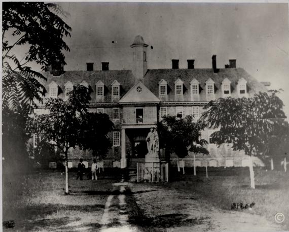 Figure 231
The Wren Building, College of William and Mary, showing a lightning conductor to the left of the pavilion. (CWF N 1960)
 Figure 232
Bruton Parish Church, showing a lightning conductor on its north side. (CWF N1489)
254
Governor's Palace, the Public Records Office and the Capitol would have also rated such protection. In addition to the alteration of the Public Hospital's conductor in 1789, there are at least seven other lightning conductor references in James Anderson's ledger of 1789-1799.19 A systematic manuscript search would undoubtedly uncover more references to Anderson's and other blacksmith's work in and around Williamsburg. In fact, a glance through any book showing early views of architecture in the Chesapeake, for example Johnston and Waterman's The Early Architecture of North Carolina, will document many examples of lightning conductors albeit many dating to the nineteenth century.20
CONDUCTOR GROUND PROTOTYPES
Similar in form to the hospital's ground is one that was excavated at Kingsmill near Williamsburg on the James River.21 Shown on the excavation plan (Fig. 233), the wrought iron conductor ground was found on the exterior of the west wall of the house built before 1736. Artifacts associated with the anchor's installation include creamware (post 1770) and a piece of painted pearlware (1785-1800), establishing a terminus post quem of 1785.22 The terminus ante quem can be established as 1844, the date of Kingsmill's destruction by fire.23
The Kingsmill ground is very similar in form and overall dimensions to the hospital's (Fig. 234 - 235). The major differences are a perpendicular neck section, and stakes that are
Figure 233
Plan of Kingsmill Plantation mansion, showing lightning conductor ground on its west side. (Virginia Research Center for Archaeology)
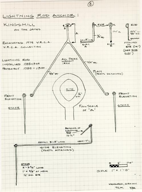 Figure 234
Lightning conductor ground from Kingsmill. (Drawing by Travis C. McDonald)
Figure 235
Kingsmill lightning conductor ground in-situ. (Photograph: Virginia Research Center for Archaeology)
255
actually attached to the arm eyes (Figs. 236 - 237). The small remnant of a conductor is also smaller in diameter than the hospital's. Considering the similarity, the Kingsmill ground was most likely constructed in the late eighteenth, early nineteenth century.
Another clearly documented example of a conductor anchor in Williamsburg was photographed at the Benjamin Waller House in 1951. The photograph of a foundation trench shows a portion of the conductor ground anchor and its link with the conductor (Fig. 238). It is identical to the hospital anchor: square wrought iron arms; a horizontal neck of about 9" - 10"; a round neck eye; and a hooked-on conductor. Presumably, the ends of the anchor are secured by long stakes driven into the ground.
The nature of the ground anchors at the George Reid, Bracken or Palmer Houses is not known,but there is some indication of the Braffertons' conductor anchor. A portion of the latter was seen during the excavation for a utility trench within the past two years.24 The top of the perpendicular neck that rises above grade (Fig. 239) was described as connecting to horizontal arms that forked, seemingly a common form of anchor. A restoration progress photograph of the Wren Building shows a perpendicular anchor neck that appears to be identical to that seen above grade at the Brafferton (Fig. 240). The fact that lightning conductors were ordered for the Wren Building, the Brafferton and the President's House in 1771 indicates that their
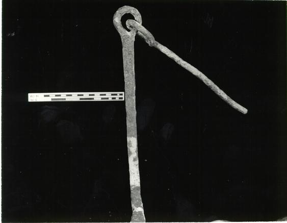 Figure 236
Detail of neck and connecting link, Kingsmill lightning conductor ground. (Photograph: Travis C. McDonald)
 Figure 237
Detail of arm and spike connection, Kingsmill lightning conductor ground. (Photograph: Travis C. McDonald)
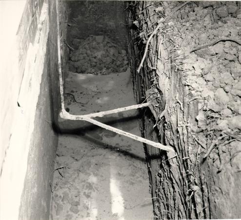 Figure 238
Lightning conductor ground, Benjamin Waller House. (CWF 51-W-700)
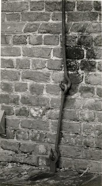 Figure 239
Brafferton Hall lightning conductor and its connecting link with its buried ground. (CWF 83-1047s-EAC)
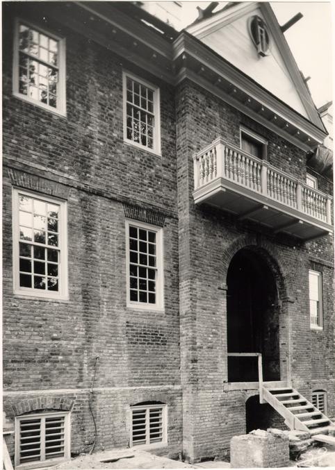 Figure 240
Restoration progress photograph of the Wren Building, College of William and Mary, showing the connecting link of the lightning conductor and the neck of its ground in the corner. (CWF L-659)
256
anchors and conductors were made at the same time by the same person.25
Two other lightning conductor grounds came to light through archaeology after the rediscovery of the hospital's ground. In August of 1983, the eye of a wrought iron lightning conductor ground was seen sticking out of the earth near the north wall of the Bruton church tower (Fig. 241). This location corresponded to a lightning conductor seen in old photographs of the church steeple (Fig. 232).26 Believing that this was an eighteenth-century ground, archaeologists were asked to excavate it in hope of shedding comparative light on the hospital's ground. Excavation revealed that a concrete trough had been poured around the tower walls below grade, encasing the protruding neck of the conductor ground (Fig. 242 - 243). This exposed piece was similar to the connecting link of the hospital's ground, a wrought iron bar ¾" in diameter whose end was bent to form an eye. Excavation continued in hope that the arms of the ground would be revealed. This proved to be partially successful.27 The end of one arm was found to be sticking out of the concrete about 7" (Fig. 244). This arm appeared to be about 3' in length and had its end eye staked into the ground by an inter-hooking spike. Presumably the other arm was covered by the concrete. What this revealed was a ground very similar to those already documented. The 1' 6" depth of the arm would make its connecting link about 6" shorter than the hospital's.
 Figure 241
Bruton Parish Church. Neck of lightning conductor ground on north side of tower. (CWF 83-DS-4341)
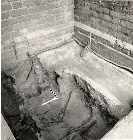 Figure 242
Archaeology of Bruton Parish Church lightning conductor ground. PHotograph shows above grade neck in the center and the end of one arm with its spike just to the left of the dimensional strike. (CWF 83-DS-4342)
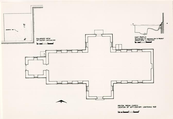 Figure 243
Plan and section of the Bruton parish Church lightening conductor. (Drawing by Virginia Caldwell) (CWF 83-FD-4493)
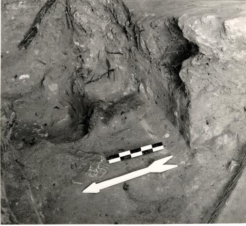 Figure 244
Detail of the arm and spike of the Bruton Parish Church lightning conductor. (CWF 83-DS-4343)
The other discovery occurred at the Tazewell Hall site in 1984 where an excavation was already underway. This was not as fruitful, however. Tazewell Hall's west wing, demolished in 1836, revealed a lightning conductor ground trench on the south side of the west wing and hyphen juncture (Fig. 245). The ground had been salvaged when the wing was demolished, but its two spikes were left behind, delineating yet another Y shaped ground. These ½" diameter spikes, with a ½" x 1" eye hole, were 2' 10" in length (Fig. 246). Assuming the conductor dates to the building's completion, 1762, or within a decade or so after that, it provides further documentation of a consistent local form for conductor grounds.28
An example farther afield can be found at Drayton Hall (1738-42) on the Ashley River near Charleston, South Carolina. During archaeological investigations in 1975, a lightning conductor anchor was discovered 3.5 feet below grade next to the south wall.29 This wrought iron v-shaped anchor, constructed of two 4' arms and an eye, was placed horizontally in the ground with a 4' link hooked onto its eye and extending upward. The major difference in form as compared to the Williamsburg area anchors is the absence of any kind of stakes and the construction of the eye without a neck section. Along with white salt-glazed stoneware sherds were two pieces of transfer-printed pearlware, thought to establish a terminus post quem of 1795. A recent reevaluation of the artifacts has established a probable installation date of 1810.30
 Figure 245
Plan of Tazewell Hall, showing location of lightning conductor. (Drawing by Virginia Caldwell) (CWF 86-371)
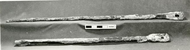 Figure 246
Two spikes from the Tazewell Hall lightning conductor. (CWF OEC B84-0187)
CONDUCTOR PROTOTYPES
The surviving examples of old conductors in Williamsburg exhibit a pattern of basic construction. Most important as a prototype is the Brafferton lightning conductor. There is no evidence to suggest that this is not the original conductor placed on the building ca. 1771. The 1932 architectural report for its restoration is further confirmation of this: "The old lightning rod which was formerly on this face (west) of the building has been repaired and reset."31 The Brafferton's conductor is composed of a 1' 7 ½" connecting link whose hook is attached to the perpendicular neck of the ground anchor and whose eye is attached to the hook of the principal conductor rod (Figs. 247 - 249). Four foot sections of 7/8" diameter iron are wrought together into a single piece that is held to the brick wall with wrought iron holders. The conductor bends around the cornice and eaves, following the roof line to the chimney where it is hooked to a tapered point that bends around the cap and rises above it.
The George Reid House offers a similar example. In this case, however, the connecting link has been replaced with a modern wire cable. Wrought iron pieces 5/8" - 11/16" in diameter are wrought together in a continuous piece that extends from the bottom hook up the chimney to where it hooks onto a 3' - 4' tapered point link that rises above the chimney (Figs. 250-252). The conductor is attached to the chimney by six wrought iron holders.
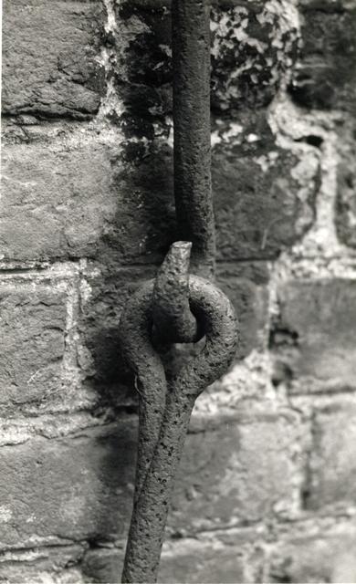 Figure 247
Hook and eye juncture of the Brafferton's lightning conductor with its connecting ground link. (CWF 83-1016s-EAC)
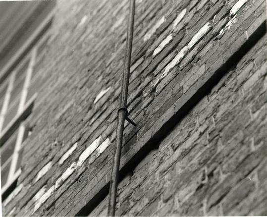 Figure 248
A wrought iron holder secures the continuous conductor to the Brafferton's wall and enables it to clear the beltcourse. (CWF 83-1048s-EAC)
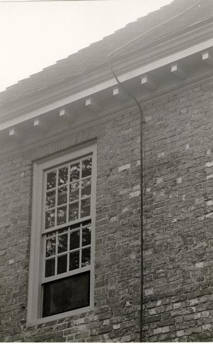 Figure 249
The Brafferton's conductor bends around the cornice and leads to the chimney. (CWF 83-1046s-EAC)
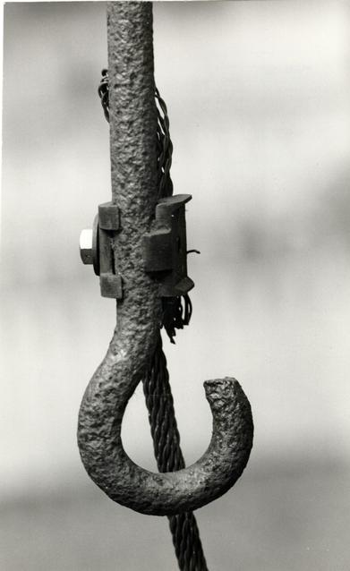 Figure 250
The hooked end of the George Reid House conductor with a later braided wire conductor to the ground. (CWF 83-1021s-EAC)
 Figure 251
George Reid House lightning conductor attached to chimney by wrought iron hooks. (CWF 83-1020s-EAC)
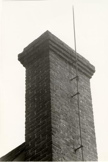 Figure 252
George Reid House lightning conductor. (CWF 83-1019s-EAC)
Attached to the west wall of the Benjamin Waller House is another surviving conductor.32 Although it breaks the pattern of having a transitional connecting link between the anchor and the conductor, it conforms to the construction pattern of multiple lengths of iron wrought together as one piece. A possible joint can be seen about 11' above grade. As with the Brafferton and Reid examples, the conductor is continuous until it hooks onto the point link (similar to Brafferton's point) attached to the chimney (Figs. 253 - 254). Benjamin Waller added the western portion of this house sometime in the third quarter of the eighteenth century, perhaps installing the conductor at the same time.
The Tayloe House retained its lightning conductor until June, 1981. At that time it was removed and stored in the warehouse yard. Like the Brafferton, Reid and Waller examples, the Tayloe conductor is a continuous piece of wrought iron 5/8" in diameter that bent around the cornice and eaves and hooked onto the chimney point link. When it was removed, the broken end of the conductor was found clamped onto a modern 10' 2" spike; a hook might have originally formed the end of the conductor. Wooden blocks had replaced wrought iron holders that held the conductor to the weatherboards. The top chimney point link is 10' 9 3/4" long and similar to that on the Brafferton and Tayloe House. The Tayloe conductor and point were used as a model for both the Palmer House conductor (Fig. 255) and the west conductor of Providence Hall.33
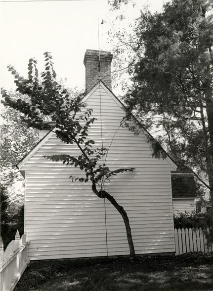 Figure 253
Benjamin Waller House lightning conductor. (CWF 83-1728s-TCM)
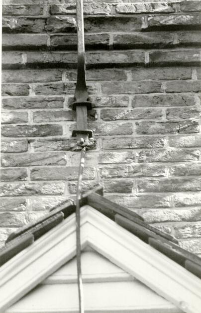 Figure 254
Benjamin Waller House lightning conductor top point on chimney. (CWF 83-1726s-TCM)
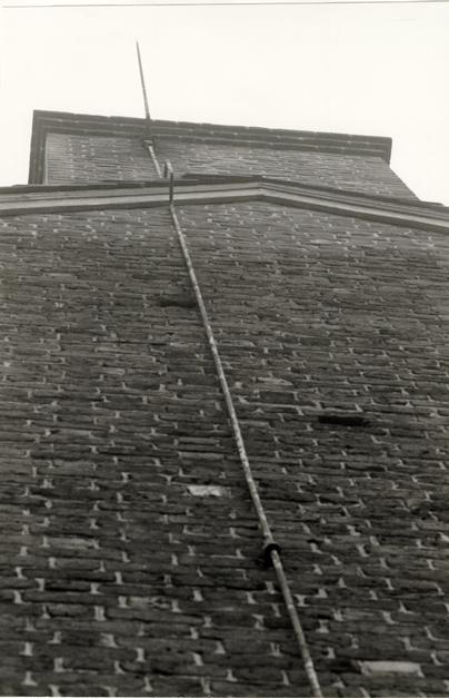 Figure 255
Palmer House lightning conductor, (CWF 83-1022s-EAC)
Strawberry Hill in Petersburg, Virginia, retains its late eighteenth- or early nineteenth-century conductor. The conductor covers the brick seam of the 1818 addition on the north elevation indicating that either the conductor is original to the 1790 house and was reused on the addition or it was installed with the addition. The eye of a perpendicular anchor neck or a connecting link is just visible above the concrete which was later poured around it. Hooked onto this eye is the principal wrought iron conductor of 7/8" - 15/16" diameter. The conductor, attached to the brick wall with wrought iron staples, hooks under the eaves, bends around the cornice and extends for 6' 3 ½" before hooking onto another wrought iron link (5/8" - 7/8" diameter, 9' 1 ½" long) which, in turn, is hooked to the chimney point link (¾" diameter, 15' 8" long) (Figs. 256-257). The top link splits into three points at its end and has an off-set bend that reflects a lower chimney cap of some earlier date (Figs. 258-259).
Farther away at Tuckahoe in Goochland County, a conductor on the south wing is partially in situ on the lower part of a chimney wall.34 This is not like Williamsburg examples, being unusual in its form and elaboration. Wrought iron pieces square in section and typically 4' 6" in length are linked together by hooked ends (Fig 260). The now unattached top piece is a cross-shaped forked piece with five points (Figs. 261 - 262).
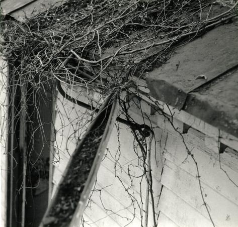 Figure 256
Strawberry Hill, Petersburg, lightning conductor, showing a connecting link as it bends around the cornice. (CWF 82-5633-TCM)
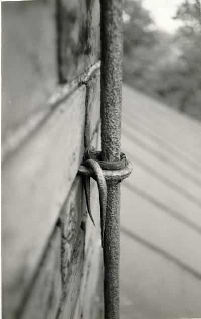 Figure 257
Strawberry Hill, Petersburg, lightning conductor showing wrought iron staple and wooden insulator. (CWF-82-5623s-TCM)
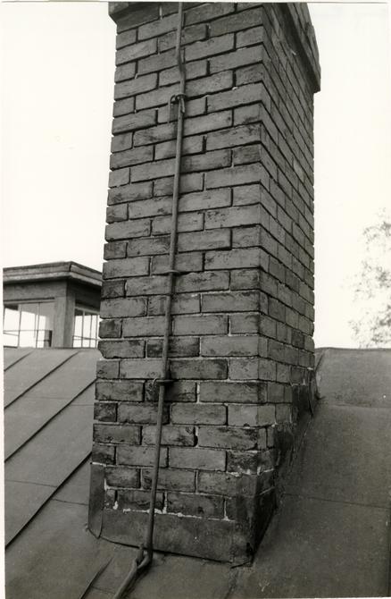 Figure 258
Strawberry Hill, Petersburg, lightning conductor attached to chimney. (CWF 82-5622s-TCM)
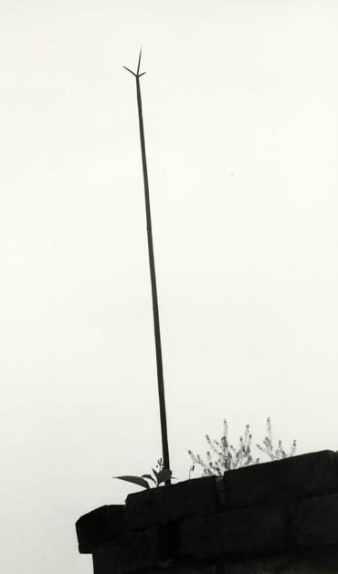 Figure 259
Strawberry Hill, Petersburg, lightning conductor point. (CWF 82-5637s-TCM)
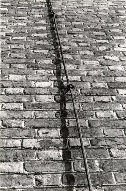 Figure 260
Tuckahoe, Goochland County, lightning conductor. (CWF 83-4754s-WJG)
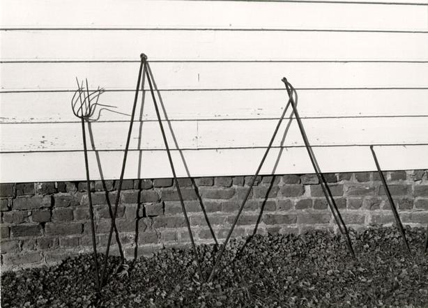 Figure 261
Tuckahoe, Goochland County, lightning conductor. (CWF 83-4771s-WJG)
 Figure 262
Tuckahoe, Goochland County, lightning conductor top point. (CWF 83-4824s-WJG)
While a detailed regional investigation might determine whether the construction pattern of lightning conductors in Williamsburg is in any way indigenous, a comparison with the high concentration of contemporary conductors in Old Salem, North Carolina does hint at that. In an examination of seven eighteenth- and early nineteenth-century conductors, a local pattern emerged which indicates that to some extent the construction of lightning conductors was dependent on the experience of the maker, as well as prototypes.35 The Old Salem conductors used for comparison are distinguished by three common features: they all go directly into the earth without any sort of connecting link (no anchors have been documented or seen) (Fig. 263); the conductors are constructed of joined rather than wrought pieces forming one piece (4 lapped and joined and 2 hooked) (Figs. 264 - 266); and the top points are part of a longer conductor link rather than a shorter piece attached by a hook (Fig. 266). The two eighteenth-century examples have a documented installation date of 1788; these are the two examples with hooked connections, whereas the other four early nineteenth-century examples use lapped pieces held with rivets or bolts.36
DESIGN
Location
The location of the reconstructed conductor, on the south elevation near the south pavilion/west wing wall juncture, was based on the location of the surviving ground. Although the
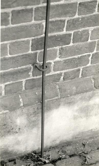 Figure 263
John Vogler House, Old Salem, North Carolina, lightning conductor and wall fastener. (CWF 82-5490s-TCM)
 Figure 264
John Vogler House, Old Salem, North Carolina, rivet juncture of square lightning conductor. (CWF 82-5488s-TCM)
 Figure 265
Single Brothers House, Old Salem, North Carolina, hooked connection of conductor and wrought iron staple holder. (CWF 82-5476s-TCM)
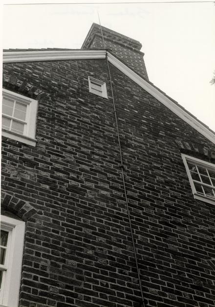 Figure 266
Salem Tavern, Old Salem, North Carolina, lightning conductor of long hooked sections held by wrought iron staples. (CWF 82-5464s-TCM)
262
photograph of the hospital's south elevation shows a replacement conductor, this provided further documentation. The Wren Building conductor was in a similar location in relation to the pavilion and wing walls, the difference being that this example was on the facade.
Placement
Placement and attachment of the conductor was established by two prototypes: Brafferton Hall and the Home Moravian Church in Salem. Brafferton Hall's conductor is the most logical prototype because it is relevant in both time and place. However, the presence of a cupola necessitated another prototype, that of the Moravian Church. From the ground and connecting link, the hospital conductor runs up the wall, bends around the cornice, and runs in a direct line west of the pavilion's hip roof valley to the base of the cupola (Fig. 267). At this point it connects to another piece that is attached to the cupola and up to the weather vane (Fig. 268).
Hooks
Wrought iron hooks to hold the conductor to the wall and the cupola were based on those at the Brafferton. The Home Moravian Church has a similar hook holding its conductor to the cupola. Similar hooks are also found at the George Reid House, the Palmer House and at the Roberts House in Isle of Wight County. A common variation of this, seen at Shirley, Berkeley
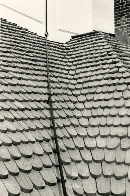 Figure 267
Public Hospital lightning conductor and its connection at the cupola base. (CWF 85-TCM-1053, 19AS)
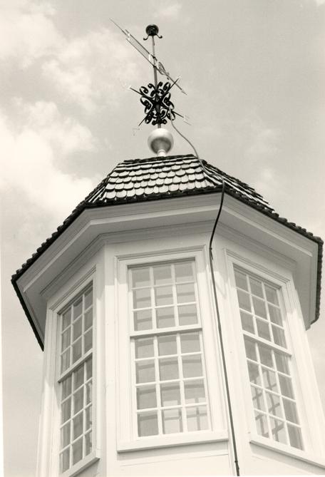 Figure 268
Public Hospital lightning conductor. (CWF 85-TCM-1053-20AS)
263
and several Salem houses, features a hook that has a flatter shank and a thicker, wider hook (possible nineteenth century); these hooks are generally an open circle that is not bent around the conductor. The other common type of hook is a simple staple, examples of which are found at Tuckahoe, Strawberry Hill and houses in Salem. James Anderson's ledgers also refer to staples for conductors.
Three wall hooks were located five feet above grade, just above the belt course and just below the cornice, as at Brafferton Hall. These were driven into mortar joints using a lead sleeve for tightness. The two cupola hooks, just below the eaves and at the base, were based on the Home Moravian Church (Fig. 269).
Historically, conductors seem to have simply laid on a roof surface without attachment; the Brafferton's roof attachment is thought to be modern. In order to be in conformance with the National Fire Protection Agency codes, the addition of two roof hooks was recommended. These wrought iron hooks were similar to the other hooks but made to screw to the surface of the shingles (Fig. 270). This concession and the fact that the reconstructed conductor would be bonded to the modern system via the weather vane satisfied a representative of the Lightning Protection Institute that the two systems were compatible.37
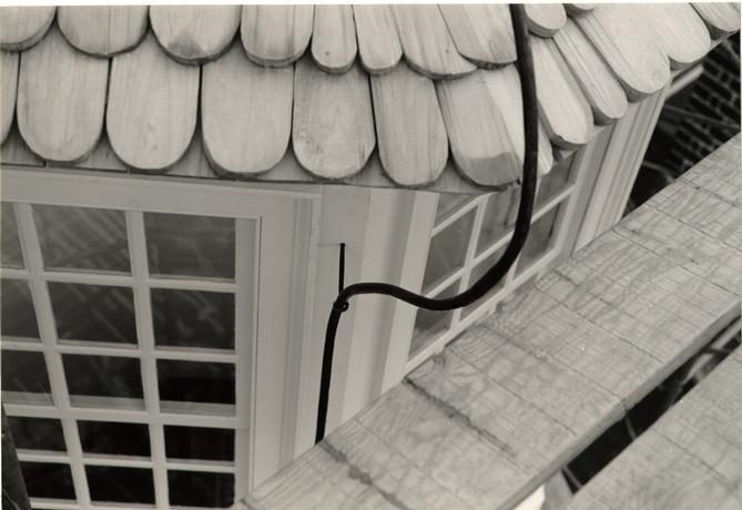 Figure 269
Public Hospital lightning conductor showing its wrought iron holder and its bend around the cupola cornice. (85-TCM-41-27)
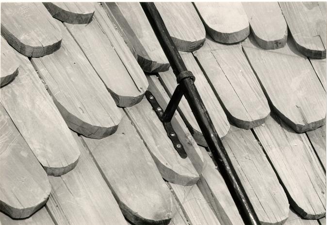 Figure 270
Public Hospital lightning conductor and its attachment to the roof shingles. (CWF-85-TCM-1053-17AS)
Conductor
The original connecting link that provided the transition between the Public Hospital's conductor and its ground provided the ¾" diameter size of the whole conductor. Examples at Brafferton Hall, Strawberry Hill and Kingsmill indicate that the necks or eyes of grounds, connecting links and the principal conductor were generally made from the same size stock. Because of its nature, the numerous lengths of iron wrought together as a continuous piece vary as much as ½". The continuous conductor from connecting link to cupola link was based on Brafferton Hall. The length of the connecting link, 4' 2", was determined from a field measurement after the conductor was in place.
Ground
Although the hospital conductor ground was the only truly authenticated part of the design, it was the part that did not actually have to follow precedent because of its location below grade. Nevertheless, due to its functional necessity, a hand wrought Y-shaped ground was made of 1" square stock. This was slightly smaller than the original, having 28" long arms spread 32" and a 7 ½" long neck.
Weather Vane Connection
There were two alternatives for attaching the lightning conductor to the weather vane, either through the bottom of the ball or over its surface. The committee first chose the former 265 option. This was based on the example of the Home Moravian Church in Salem, the prototype for the conductor-cupola attachment (Fig. 271). The committee later reversed its decision and chose the second option. This, too, was partially based on a Moravian church at Bethabra, North Carolina, whose lightning conductor clamps directly onto the weather vane spindle (Fig. 272). It was also felt that the perpendicular hook above the ball on the Christ Church, Shrewsbury, New Jersey, vane might have held a conductor. The Public Hospital weather vane was most likely placed on the cupola before the installation of the conductor. This sequence would suggest a direct, external method of attachment. Close examination of Bruton Church photographs reveal a conductor that seems to pass over the ball on the steeple (N 1489). The end of the hospital conductor was bent 90 degrees and flattened out to form one half of a clamp to which the other half was bolted around the spindle (Figs. 273-274).
Finish
There are no specific references to painting lightning conductors in Williamsburg. There is an 1802 recipe in the Domestic Encyclopedia for coating lightning conductors with a crust of black lead formed from melted sulphur.38 Based on specifications for painting weather vanes, the conductor was also painted black.
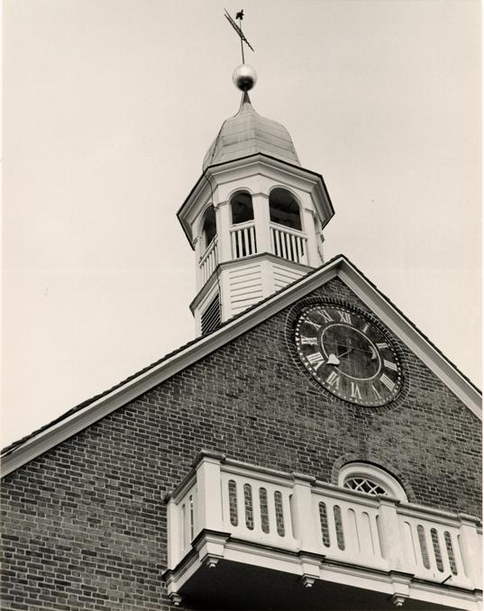 Figure 271
Home Moravian Church, Old Salem, North Carolina, lightning conductor attaches to base of weather vane at base of ball. (CWF 84-TCM-2611-7A)
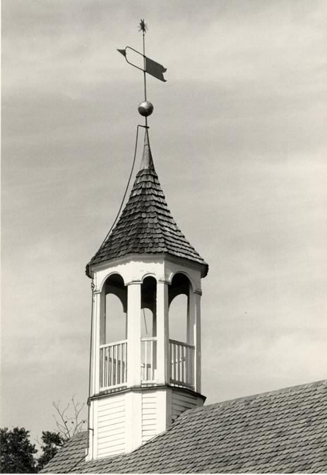 Figure 272
Wrought iron lightning conductor on the Moravian Church at Bethabara, Winston-Salem, North Carolina (Old Salem photograph). (CWF #86-410)
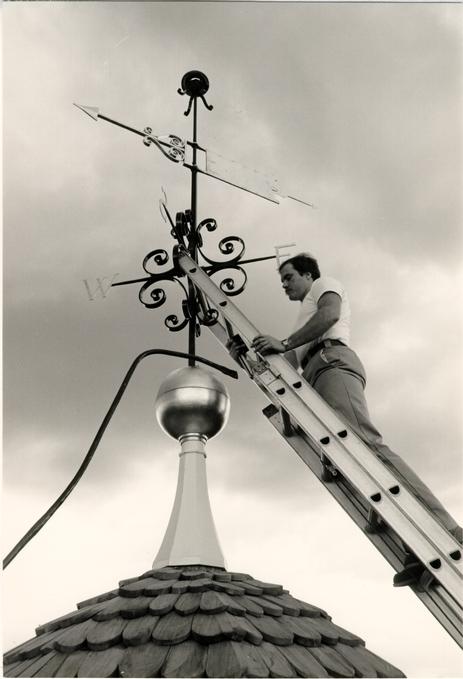 Figure 273
Public Hospital lightning conductor being attached to weather vane spindle. (CWF 85-TCM-43-29)
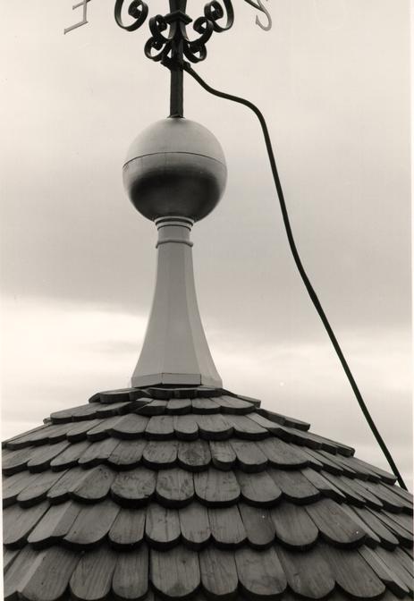 Figure 274
Public Hospital lightning conductor showing its method of attachment to the weather vane. (CWF 85-TCM-41-36)
CONSTRUCTION
Two sheets of working drawings were completed in April, 1983 and given to Peter Ross. The length of the conductor posed an immediate production problem. Given the small space in the Deane Forge shop, the solution to forging a long continuous conductor was to open a hole in the rear forge chimney wall. This enabled the conductor to extend out of the chimney as new pieces were wrought onto the length (Fig. 275). Square stock was hammered into the ¾" diameter round conductor (Figs. 276-277).
With scaled drawings of the hospital, the blacksmiths staked out the full scale wall, roof and cupola on the ground with string. Using the crook of a nearby tree, they then bent the two sections of the conductor, the lower section with its bend for the cornice and the upper section with its bend for the cupola cornice and roof. The conductor's top piece was installed first in order to take advantage of the cupola scaffold (Figs. 278 - 279). Whereas the top section of the conductor was painted in the paint shop, the lower section was hand carried from the Deane Forge to the hospital site by five men and then painted at the site before installation (Fig. 280). The final installation was that of the connecting link and ground in May, 1985 (Fig. 281). Because of the presence of the gallery tunnel roof, the ground was placed 18" below grade and was installed without the use of spikes.
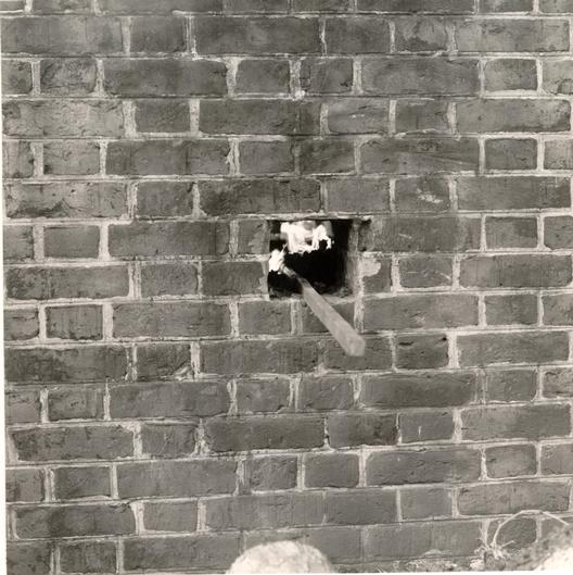 Figure 275
Rear chimney wall of the Deane Forge showing the lightning conductor sticking out. (CWF 84-DS-2238-9s)
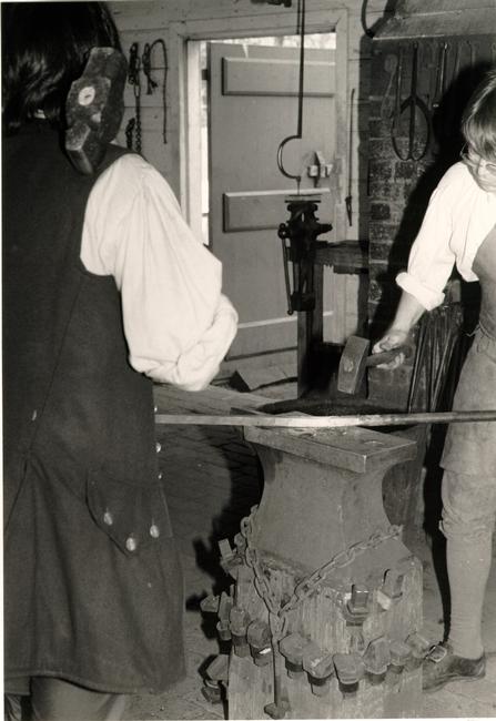 Figure 276
Square lengths of iron rod are hammered together and then the edges are hammered to produce a round rod. (CWF 84-TCM-2320-25A)
 Figure 277
Detail of the lightning conductor stock rod before (square) and after (round) it is hammered. (CWF -84-DS 2239-12s)
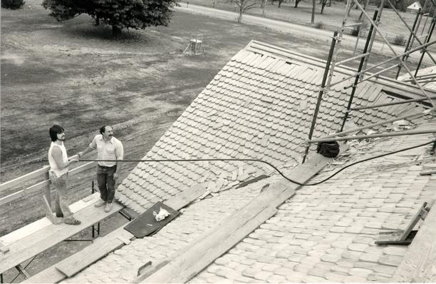 Figure 278
Installation of the conductor's top piece. (Ken Schwartz and Peter Ross) (CWF 85-TCM-43-22)
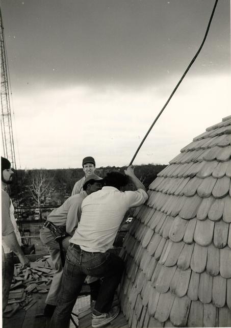 Figure 279
Installation of the conductor's top piece. (CWF 85-TCM-43-31)
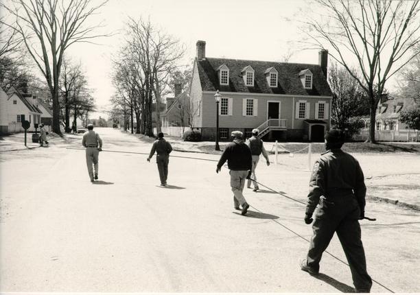 Figure 280
The lower section of the conductor is carried from the Deane Forge to the Public Hospital. (CWF-85-TCM-1054-7s)
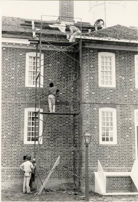 Figure 281
Installation of the conductor's bottom section. (CWF 85-TCM-1054-33s)
CHAPTER XXVII
NOTES
| 1789 | The Lunatic Hospital | |
| Aug 25 | To taken down and putting | £ |
| up the Conductors | .10.- | |
| To Altering Ditto 2/6 | .2.6 | |
| By 69wt of old Iron @ |
It has pleased God in his goodness to Mankind, at Length to discover to them the Means of securing their Habitations and other Buildings from Mischief by Thunder and Lightning. The method of this: Provide a small Iron Rod (it may be made of the Rod-iron used by the Nailers) but of such a Length, that one End being three or four feet in the moist Ground, the other may be six or eight Feet above the highest Part of the Building. To the upper End of the Rod fasten about a Foot of Brass Wire, the Size of a common Knitting 268 needle, sharpened to a fine Point; the Rod may be secured to the House by a few small Staples. If the House or Barn be long, there may be a Rod and Point at each End, and a middling Wire, along the Ridge from one to the other. A House thus furnished will not be damaged by Lightning, it being attracted by the Points, and passing thro the Metal into the Ground without hurting any Thing. Vessels also, having a sharp pointed Rod fix'd on the Top of their Masts, with a Wire from the Foot of the Rod reaching down, round one of the Shrouds, to the Water, will not be hurt by Lightning.
I believe no country has more certainly proved the efficacy of electrical rods, than this: before the discovery of them, these gusts were frequently productive of melancholy consequences; but now it is rare to hear of such instances. It is observable that no house was ever struck, where they were fixed: and although it has frequently happened that the rods themselves have been melted, or broken to pieces, and the houses scorched along the sides of them, which manifested that they had received the stroke, but that the quantity of lightning was too great to be carried off by the conductor, yet never has any misfortune happened; such a direction having been given to the lightning, as to prevent any danger or ill consequence. These circumstances, one would imagine, should induce every person to get over those prejudices which many have entertained; and to consider the neglect, rather than the use of them as criminal, since they seem to be means put into our hands by Providence, for our safety and protection.
Mary R. M. Goodwin, William and Mary Historical Notes, Vol. II, page 204, Colonial Williamsburg Foundation.
Journal of the Meetings of the President and Masters (1729- 1784):
"Resol: that Points & Conductors be fix'd on the College, the President's House, & the Brafferton-School: that the Direction of the same be left to the Revd Mr. Gwatkin Professor of Mathematics."
No evidence has been found of the conductor on the President's House.
p. 31 George Carter 1790 June 20 New bottom for Lightning Spire 15/6
p. 87
John Hicks Richmond
1791
June 9 To a Conductor for a Chimney 184 wt @ 8d 66..2..8
To a Brass Point Ditto 6/ putting up Ditto -12..-
p. 170 John Hopkins
1793
Apr 9 To repairing point of a Conductor 3/
To taking down and putting up ditto 10-
To a staple 7 ½ -..7 ½
p. 227 Mr. Banjmain Harrison 1793 April 25 To a Conductor 170 lbs @9 6..7..6
270 To a brass point for ditto 7/6 7..6
To two eyes for ditto 1/6 3..-
To two staples 1/2. putting up ditto 6/ 7..-
p. 244
Doctr. James Currie
1793
July 9 To Lenghting a Conductor & bottom iron 57 ½
2..3..1
To two eyes 3 ¼ lb 2/5 ½ two large staples
½ -3..8 ½
To taking down and putting up ditto 2..-..
p. 265
John Barret
1794
May 4 To putting up lightning Rod 6/ four staples 3/
-9. -
To lengthening ditto 12 ob 9d -9..-
p. 312
James Cringham
1795
May 2 To 5 Staples for leghtning Rod @ 8d -3..4
To altering the Conductor &c -5..-
There is another group of references to James Anderson in The Order Book and Related Papers of the Common Hall of the Borough of Norfolk, Virginia, 1736-1798 (Richmond: Virginia State Library), 1979. Curiously, James Anderson is listed in 1786 as a Freeholder citizen of Norfolk (reference from John Hemphill). There is also reference in the same order book to William Anderson (relationship unknown) working on a conductor in 1797:
p. 259 28 May 1788 James Anderson employed to "Erect a Conductor to the Magazine: £ 11.16.10."
p. 401-402 15 Aug 1797: The Committee Appointed to Examine into the State and Situation of Franklin on the Magazine and have the same fixed up, report, that they had Employed William Anderson to have the said Work done whose Account Amounts to Three pounds ten shillings and Sixpence.
Domestic examples, primarily from photographic evidence include: Monticello; Sabine Hall (1773 diary entry of Landon Carter); Powhatan; Berkeley; Shirley; Fairfield, Gloucester; Ye Dudlies, Virginia Beach; Tuckahoe, Goochland County (Agricultural Buildings Project files); Robert House, Isle of Wight County (photographed); Mount Clare, Md.; Ridout House, Annapolis (slides by Mark R. Wenger); No. 7 Meeting Street, Charleston (photograph by Willie Graham); Mulberry near Charleston; Clivedon, Pa.; Mt. Airy, Va.; the Pine Street Presbyterian Church, Philadelphia; the Cadwalader House in Philadelphia (1770 87.4.1); the Moravian Seminary, Pa.; and the Longfellow House, Ma.
A lightning rod, probably a century old or more had been attached to the west chimney. Because of its essential usefulness and because of historical associations, it was retained. Although it was rebuilt, it retained all of the old rod, including the topmost needle point. New ground connections were provided.
An answer has been received from Pa. about lightning rods. There will be a meeting of the Conferences and other interested Brn. to discuss the matter.
[24 June 1788] Mr. Bagge is willing to have a lightning conductor set up on the Store, if he can persuade his wife, who does not like it. Since the Store is built at an angle, the conductor can serve for both wings. It is not advisable to install the conductor at the other part of the wing, because that part of the house contains too much steel and iron ware.
273 Afterwards conductors shall be installed at the tavern, which will serve also two wings. We think that it will be good to have the conductors a little bit distant from the house, also to lead them a few feet above the ground away from the houses, rather than lead it into the ground first.
[19 June 1788] It was furthermore reported that the Single Brethern have installed the first lightning conductor on their house. At the installment they took the necessary precautions so that no body would be harmed by it. Br. Christ. Vogler wishes that people who want him to make a lightning conductor for their houses inform him of this, since he has too much work to do it later on.
Other references indicate that eighteenth-century conductors existed on the powder house, 1790; the School House, 1794. An early nineteenth-century conductor appeared on the Gemeinhaus, 1803.
THE PUBLIC HOSPITAL:
AN ARCHITECTURAL HISTORY AND
A CHRONICLE OF RECONSTRUCTION
Architectural Research Department
Colonial Williamsburg Foundation
Williamsburg, Virginia
1986
CHAPTER XXVIII
EXERCISE YARDS
DESCRIPTION
Exercise yards, 32' 1" x 82' 0", flank the Public Hospital on the east and west (Fig. 282). The east yard represents a historical use while the west yard is used for handicapped visitor access and other modern conveniences. The wooden fences that define the yards are conjectural designs; only the type of wood and the vehicular gate in the west yard fence are features known to have existed at the Public Hospital. The fence is composed of 8" square posts, four 2 ½" x 4" rails per panel, and 3/4" thick pales of 6" - 10" random width. Posts and pales extend 11' 8" and 11' 10" high from grade respectively (north elevation). Each yard has a 3' 9" wide pedestrian gate. Refer to drawings PH-8, PH-9 and PH-130.
DOCUMENTATION
On the one hand, documentation for the physical evidence of the exercise yards is strong, yet on the other, the written evidence is confusing and will always remain something of a mystery. Archaeology provided the location of nearly every fence posthole in the east yard and partial evidence for those in the west yard (Fig. 283). Initially, the written documentation seemed to fit into the picture very nicely. The hospital directors reported to the House of Burgesses in February 1772
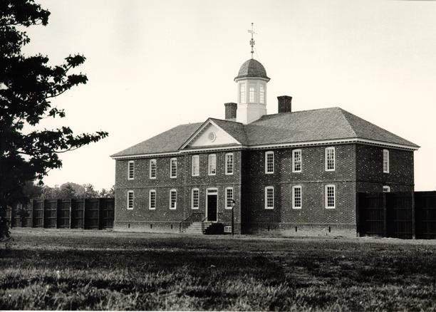 Figure 282
The Public Hospital flanked by its exercise yard fences. (CWF 85-WW-408-3s)
 Figure 283
Archaeologists excavate the east exercise yard. (CWF 80-FD-4398E)
275
that it would "be necessary to inclose a Garden and Yards for Patients to walk and take the Air in … ." The Burgesses responded immediately and authorized £800. The work was advertised in July and in December of the following year Benjamin Powell was paid a sizeable sum for "paling in the Lots belonging to the Hospital."1
This neat combination of physical and written documentation was soon found to be impossibly connected. Ivor Noël Hume reported "with confidence" that the artifactual evidence from the postholes and posthole molds dated the fence "no earlier than ca. 1780 and probably closer to 1790 (Fig. 284)."2 He went on to say that a group of privy pit holes, that artifactually dated later than 1775, had been cut by a fence post hole, placing the fence even later. The 1772-73 references to enclosures were for a perimeter lot fence, Noël Hume reasoned, rather than any airing yards for patients. The Frenchman's and Rochambeau maps of 1781 show the hospital lots enclosed, providing further evidence of this, he felt. Noël Hume also postulated that the small number of patients, six when the institution opened, provided no urgent need for fenced yards.
With a post-colonial date for the yards in mind, all written documentation to eighteenth-century enclosures at the hospital was reexamined. Despite the authorization for "Inclosures for the Patients to walk, and take the Air in," the 1772-73 property. The large sum of £ 143.17.3 ½ also suggests this
 Figure 284
Drawing of the east exercise yard showing posthole molds and postholes. (CWF 86-374)
276
interpretation. There is also the possibility that exercise yards were built behind the hospital at this time, but archaeological evidence neither confirms nor denies this.
In March 1786 the Directors ordered "That the said Committee be authorized to employ some proper Person to make an Estimate of the Sum of Money, which may be necessary to repair the said Hospital, and other Buildings thereto belonging and to inclose the same with a proper Inclosure as it formerly stood."3 This reference and a similar one the following month would indicate that the hospital and outbuildings were being enclosed. More importantly, the words "as it formerly stood" seem to imply an earlier fence around the entire grounds, most likely the 1773 work by Powell. More explicitly, in 1787 the Directors "Ordered that the whole of the Ground belonging to the Hospital be immediately enclosed… ."4 In December of that year and in May of the following, John Saunders received £ 142..5..- for "Paling."5 These references are probably to a second perimeter fence. If the entire property was enclosed in 1773, it is not unreasonable to assume that the fences needed rebuilding by 1787. The French soldiers encamped around the hospital during the war might very well have use the earlier fences for fuel. Saunder's payment is also remarkably similar to that received by Powell in 1773.
The next reference to enclosures occurred in 1794:
These are the first clear references to exercise or airing yards for patients. They also indicate, through the use of words "enlarge," "enlarged" and "enlargement," that specific exercise yard or yards already existed by this time. If the reference to the "ground East and West" is taken to mean the area adjacent to the building, this could very well be the yards discovered by archaeology. The question remains, however, as to where the earlier yard or yards were located.May
Ordered that Mr. President, Mr. Bracken, Mr. Benjamin Waller, Mr. Andrews, and Mr. Hunt be appointed a 277 Committee any three of whom may act for the purpose of agreeing with proper workmen to enlarge the Walks or Yards of that part of the Hospital allotted to the patients so as to comprehend all the ground East and West, South of the building reserving sufficient ground for the Domestic Accommodation of the Hospital.6
November
The Court anxious that the humane intentions of the legislature is establishing this Hospital for the accommodation of the unfortunate objects of its institution may be fully answered and convinced both from their own observation and the Report of the Physician that the Yards ought to be considerably enlarged, and at the same time guarded against the inconveniency to which they are exposed in the Summer Months from being so limited in the grounds at present appropriated to their use, think it their duty to propose to the Legislature the enlargement of the Yards of the Hospital.
Resolved therefore that the Delegate from the City of Williamsburg be requested to move the Legislature to direct that the expences which it is conceived will not exceed four hundred pounds and which may be incurred in such enlargement of the Yards be paid out of the public Treasury.7
By August 1799 the Directors reported that "…from their own view … the yards in which the Patients are confined required to be entirely rebuilt, and it also appearing to the Court that a Brick inclosure will be most convenient and in the 278 end less expensive."8 James Semple entered into a contract with the Directors to provide brick walls 10' high, 2 bricks thick, 90' long, and 40' wide. Just about one year later the size was altered to 12' high from the foundation; the thickness was changed to 3 bricks thick to grade, 2 ½ bricks to the water table and 2 bricks above that; 72' in length and 47' wide.9 These brick walls are depicted on the "Galt drawing" (Fig. 43) as dotted lines which flank the building. The foundations of these walls were documented by archaeology.
The 1799 reference raises the obvious question of why, if they were built in 1794, the fences needed rebuilding just five years later. If the flanking fences were constructed prior to 1794, why is there no written record within the detailed set of minutes? The significant point is that there were yards for the patients prior to 1794, possibly from the earliest years, and that their inclusion in the reconstruction was considered crucial to a proper medical and social interpretation.
As previously discussed, an early gallery plan called for exhibition space to be housed inside reconstructed brick exercise yard walls. With the move of the gallery to a separate building, the exercise yards were dropped from the design. In June, 1981 Edward Chappell lobbied for recreation of the yards because of their visual and interpretive potential.10
The inclusion of yards won fairly easy acceptance by the Program Planning Committee. The question became one of wooden fences vs. brick walls. In the end, wooden fences 279 prevailed because of the Design Review Committee's desire to portray the hospital in its earliest period. However, the lack of evidence for an earlier enclosure pushed forward the reconstruction date to ca. 1790, so that the flanking fences could be used. The interpretive importance of including the yards, and secondarily, of attention-calling fences attached to a rather innocuous public building, was felt to be superior to holding the timeline to 1773.
There are no documented structures within the yards prior to 1800. At that time, "The Physicians to the Hospital … stated to the Court that a covered Walk within the Brick yards to the Hospital was necessary for the protection of the Patients from the heat of the Sun."11 Again in 1804, there is an account for "Building shelter in mens yard (Fig. 285)."12 After 1805, a variety of references are found to both the men's and women's yards: wells (1805); shelters (1808); steps (1810); bench (1814); double seat (1817); "Cink" (1817); doors (1820); gates (1820); spout (1825); etc.13
Segregated yards, like segregated wells, were not unusual. John Howard mentioned in his 1789 account of lazzarettos in Europe that London's Bedlam Hospital had "airing grounds for each sex (Fig. 37)." The proliferation of privately run asylums in England in the early nineteenth century commonly featured two or more yards for patients, examples being Whitney, Hook Norton, Brislington, West Auckland and Fishponds. Early American hospitals and asylums followed this pattern.
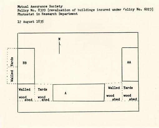 Figure 285
Mutual Assurance Society plan showing yards and indication of "wood shed" shelters. Plan drawn from original by Patricia Gibbs and Linda Rowe.
280
Ironically, the Pennsylvania Hospital first erected a "Pallisade Fence in 1760" to keep back the public "in order to prevent the Disturbance which is given to the Lunatics confined in the Cells by the great numbers of people who frequently resort and converse with them… ."14 The Pennsylvania Hospital later constructed walls for the "Lunatic yard." Other early American institutions followed suit: the New York Hospital; New York's Bloomingdale Asylum; Boston's McLean Asylum; Vermont's Brattleboro Retreat; Hartford's Retreat; Virginia's Western State Lunatic Asylum (Fig. 286); South Carolina's Asylum (Fig. 287); etc.
In fact, by the nineteenth century, it can be said that yards for patients were standard at every facility for the insane. Furthermore, yards became classified and subclassified as Moral Management treatment influenced the separation of patients by degree of infliction. Not surprisingly, this practice had been established by the Tukes at their York Retreat around the turn of the century (Fig. 61). Where formerly one would find "desolute courts, where no tree nor shrub nor flower nor blade of grass grew," the yards became relatively pleasurable and integral to treatment, as least for the better class of patients.15 At Fishponds Asylum near Bristol in the early nineteenth century, a hierarchy of yards developed, "the worst being reserved for the worst description of patients."16
In Williamsburg, at least by 1835, each flanking yard had been divided in half and the new building to the west provided with an adjacent divided yard to its rear. In each of
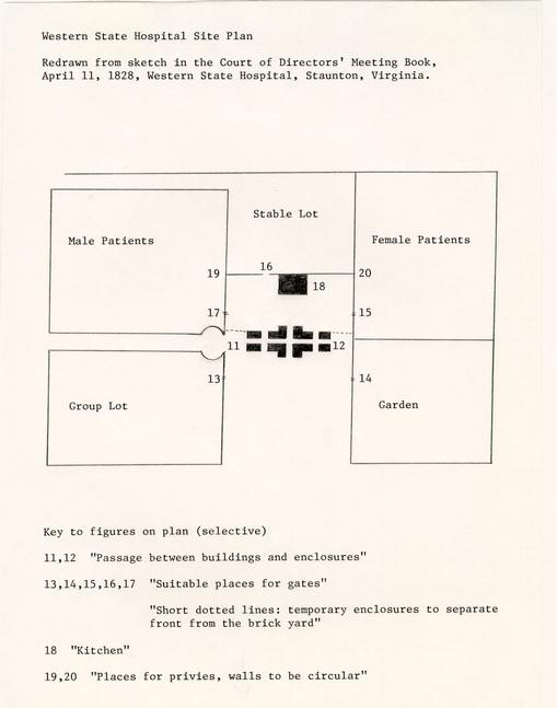 Figure 286
Site plan of Western State Hospital, Staunton, VA. Redrawn from sketch in the Court of Directors' Meeting Book, April 11, 1828, Western State Hospital Collection.
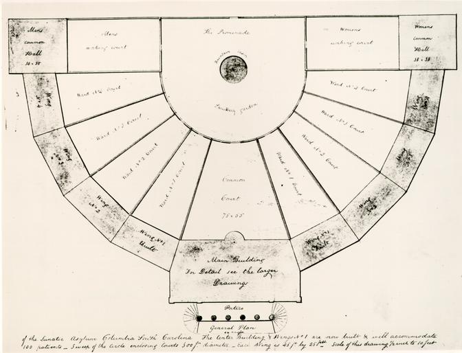 Figure 287
Lunatic Asylum, Columbia, SC. Plan by Robert Mills, ca. 1825, showing segregated yards. (CWF 84-TS-1843) From the original in the South Carolina Archives.
281
the four yards east and west of the original building were "wood sheds,"17 described in the 1835 Annual Report as a "shelter, resting on posts, so as to afford an opportunity to the patients to take the air in bad weather" (Fig. 288).18 The appointment of Philip Barziza as Keeper in June 1837 and the evidence of a more thorough application of Moral Management theories in Williamsburg after that date are not coincidence. By January 1838 the hospital's annual report indicated that exterior accommodations had taken on added importance in terms of treatment:
There are certain yards attached to the hospital, the Walls of which are high enough for the secure custody of the patients, but these are too small for the accommodation of convalescents. But there is in front of the buildings a yard [of] two acres, one half of which is surrounded by them, and the walls of the other yards. An appropriation sufficient to surround the other half with a sufficient wall, would enable the keeper to separate the convalescent from the incurable, and to afford him the advantage of light, air, shade, exercise, and amusement. [. . .] The space in question is used as a garden, and is necessarily enclosed. Were it enclosed in the matter proposed, it might still be used for the same purpose, and chiefly wrought by the hands of the patients, with great benefit to their health both of body and mind.19The proposed brick wall was built around the premises by 1841. As borne out by the 1845 lithograph by T. C. Millington and the 1855 lithograph by L. A. Ramn, the north and did taken on the appearance of a pleasure ground, with patients strolling and tending the ornamental plantings. The "incurable" patients no doubt used the original flanking yards, which were probably much like the exercise yard in Pennsylvania described by Dorothea L. Dix in 1844:
Figure 288Central State Hospital, Petersburg, VA. "Patients at rear of old Administration Building. Note Mayfield Cottage in background." No date. Library collection, Central State Hospital. 282
About half the patients last August, had the liberty of the premises; others were confined in their cells or to the wards, and a few were ranging a small enclosure called the exercise yard. This miserable place was utterly comfortless, exposed and inconvenient. The hot sun beat down upon the unconscious or half conscious patients. With bare head exposed to the direct and burning rays, they strayed around the small area, or lay extended upon the ground. Not a tree even shaded the place, and one almost felt that it was but an additional evil that they were permitted to be abroad, exposing them to the sun or the tempest, the drought, the heat, or the cold, according to the season.20Another good contemporary account, of a Canadian asylum yard, was included by John Charles Bucknill in his Notes on Asylums for the Insane in America, 1876:
It was a hot, sultry afternoon, and almost all the inmates were out of doors. I found them all congregated in one small courtyard in a tout ensemble of lunacy not easily to be described. I cannot state with accuracy the size of the courtyard, but it did not appear to me to exceed one hundred yards in breadth by eighty in depth. Whatever its size might be, it was divided into two pretty equal parts by the abovementioned brook, traversed by a bridge, and the half of the yard furthest from the building and beyond the brook was occupied by a crowd of, as near as I could estimate, abut 300 lunatics. The bridge was kept and the crowd was watched by a man lying on the ground in his shirt-sleeves, in whom it was not difficult to recognize an attendant. I was invited by my companion to observe the lunatics from the safe end of the bridge, and for some time I did so and I must say that I never in my life before saw anything like it. The lunatics appeared to be quarrelling and fighting, without the least control, and there seemed to be no attendants with them whatever. This, however, was a mistake, for after awhile I crossed the bridge, and on inquiry discovered three boyish persons, who announced themselves to be attendants. Skirmishes were still proceeding among the patients, and on my asking the attendants why they did not prevent them they gave no reply. Not only were the patients permitted to quarrel and struggle without interference, but I observed several of them lying on the ground with the most indecent exposure of the person. Considering the amount of excitement in this sweltering crowd, there was not much mechanical restraint. I observed two or 283 three men with their wrists in iron rings attached to leathern belts, which is certainly a mild form of restraint, since it leaves the muscles of the arms and chest some freedom of movement. I saw no straitwaistcoats. In front of the men's building there are grounds large enough to make fairly good airing courts, and why these are not so utilised could not be explained.
DESIGN
Research and design of the fence took place between the summer of 1982 and the spring of 1985. The first phase of design research was approached in two ways. Through illustrations and written documentation the basic form and height of the fence was determined.21 Combined with this were details of eighteenth-century fence construction, albeit from fences of normal size and function adapted to a larger scale fence.22 Because of the scarcity of material, any type of institution of confinement from the eighteenth or early nineteenth century, such as prisons, jails and almshouses, were researched along with hospitals and asylums for evidence of exercise yard fences. The reliance on nineteenth-century illustrations had its drawbacks and only those fences with clearly distinguished details were given analytical priority.
Based on illustrations, a morphological comparison of eleven institutions having wooden fence enclosured yards revealed certain common characteristics: close-set vertical pales with flat tops, pales that extend above the posts, a majority of exterior placed rails, and a height of at least 10'.23 Church vestry records in Virginia and other sources established certain 284 construction characteristics: close-set pales nailed to rails with l0d nails; triangular rails mortised into posts; a variety of wood for the different parts; hewn and sawn posts; 3/4" thick pales; and Spanish brown paint. Questions left unanswered at this stage were: placement of pales on the inside or outside of the fence, and if on the outside, were they nailed across the posts; sawn or riven rails; the number of rails; the width of pales; the surface finish of the pales; and whether the fence had a cant rail.24
Most intriguing was the question of rail placement. Was the fence constructed inside-out, with the rails on the exterior, so the patients could not climb the rails? Functionally, it was logical that the rails would have been on the exterior. The first collection of comparative illustrations hinted that this was the case, but the evidence was far from conclusive. Not until the discovery of a documentary report on Pennsylvania almshouses, the Third Report of the Committee on Lunacy, was this question resolved.25 Although the date of the report is comparatively late, 1885, it is important for its consistently detailed illustrations of almshouses and their attached fenced yards (Fig. 289). Significantly, the report documented almshouses that housed the insane, which meant that the fences were functionally comparable, despite the late date. These illustrations left no doubt that an exterior rail location was common. other new design information, based on this group of illustrations and additional information on foreign asylums,
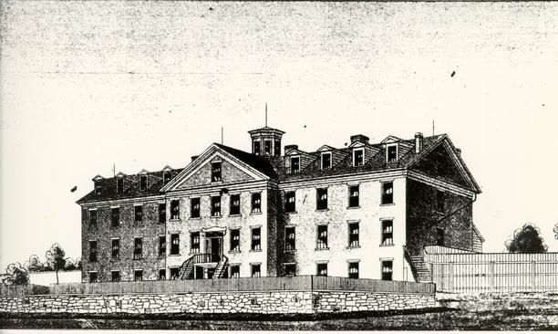 Figure 289
Blair County Almshouse, Pennsylvania. Showing exercise yard fence on right. From the Third Report on the Committee on Lunacy, 1885. (CWF 86-412)
285
included the use of two or three rails; the possible use of a cant rail; and the placement of a fence gate away from, rather than adjacent to, the juncture of fence and wall.26 Earlier design decisions regarding the pales were reinforced by this new information as well.
References to various Public Hospital fences, found in vouchers, reports or minutes, formed the basis for still other design factors. This indicated that common paled garden fences at the Public Hospital were 5' to 7' high with three rails. Based on this, the committee felt that three rails were reasonable for the exercise yard fence. Vestry book fence specifications influenced the decision that these rails be triangular in section and mortised into the posts.
Although there is an 1819 reference to "slitting plank for pails" at the Public Hospital, sawn rather than riven pales were found to be common in vestry specifications. Neve's The City and Country Purchaser and Builder's Dictionary, 1726, estimated that one could get three times the number of 1" thick x 1' broad pales by sawing rather than cleaving. Plank thicknesses at the hospital are mentioned in 1804 and 1809 as 1" and 1 ¼". Considering Neve, 1" was chosen as the pale dimension. There was no good documentation for pale width however. After a lengthy debate on random vs. uniform widths, comparative examples of historic sheathing, and width vs. warping, the committee decided that the absence of specified widths in all documented accounts 286 favored the likely use of random widths. The width was established as 6" 10".27
Eighteenth-century fences were commonly a combination of different woods. Posts were made of cedar, walnut, white oak or locust; rails were made of oak or poplar; and pales were commonly pine but also poplar or chestnut.28 Based on the frequency of occurrence, the committee decided on cedar posts, oak rails and pine pales.
The committee first dismissed the consideration of gates in the exercise yard fence based on the lack of archaeological evidence. When reexamined by James Waite, the archaeological evidence did not rule out a gate on one side at least. His analysis is given here:
The postholes of the north fence of the east yard do indeed indicate even 8' spacing, but the arrangement of the posts in the south fence of the east yard is not as simple. Starting at the east end of the south wall and proceeding west the spacing is very roughly 8' 6" to a point approximately 13' 0" from the southeast corner of the Hospital. Any intermediate posthole between this point and the corner of the building has been obliterated, so we are left to guess where one might have been. What this does give us is the extreme likelihood that there was another evenly spaced section of fence and a gate of 4' to 5' in width here. The gate would have been against the corner of the Hospital or one space away from it.29Considering both the possibility of a gate and the interpretive use of the east yard, the committee decided in favor of the fences. The existence of the west yard fence gate is based solely on the possible evidence for one in the east yard.
Written documentation was not particularly helpful regarding either the Public Hospital specifically or eighteenth 287 century gates in general. References to gates at the Public Hospital, nineteenth century in date, are generally not specific as to which fence contains the opening. There are a few specific entries: "iron straps" for a "yard door" (1815); "hart plank" and "inch plank for yard door" (1820); a gate for men and a gate for women (1820); and door frames for "nue yard" (1821).30
With the first drawings in October 1982 came additional design changes and considerations. Rail placement was set at 3' 5" apart and 1' 10" from the top of the pales; horizontal gate rail members should mortise into vertical members; and the middle horizontal gate rail should be cut and butted against the diagonal brace. The 4' gate width and the 3' 1" long strap hinges were based on a 9' high stable door at Mt. Airy. The most significant design problem brought to light by the drawings was that of intersecting rails at corner posts. To mortise the rails into the corner post at the same level would create a structurally weak joint. The initial solution involved lowering one set of rails; which unfortunately created more extended pale tops.31 In closing this first stage of design in the fall of 1982 the Design Review Committee called for the construction of a fence mock-up and for a construction cost estimate.32 Unfortunately, the CW crafts carpenters could not undertake the job of pit-sawing the fence lumber due to prior commitments.
Between the fall of 1982 and the summer of 1984, the fence project lay dormant. The design was seemingly completed except perhaps for the question of the rails joining the corner 288 posts. Two corner panels were constructed during this period however (Fig. 290). As with all mock-ups, this proved to be beneficial in a number of ways. In terms of materials, it was determined that the band-sawn lumber worked well and that galvanized boat nails with re-hammered heads looked as good as real wrought nails. In the process of painting the fence Spanish brown, it was learned that the fence parts would have to be painted prior to assembly. The manner of assembling the rails to the posts was also brought into question through this mock-up.33
By the time the committee had again turned to the design in June 1984, significant new documentation had come to light.34 The most significant of these were from Chowan County, North Carolina, for a gaol fence and from Richmond for a poorhouse:
The initial design had been based on a combination of general references regarding overall form and characteristics from construction specifications, albeit those from ordinary and common fences. The significance of the two sets of specifications cited above is that they are functionally comparable, i.e. the fences contained people, and they offer details of construction. Based on the Richmond example, the fence rail design was altered from triangular to four 4" x 2 ½" lapped rectangular rails. The reference to lapped rails led to the conclusion that they would necessarily have to be staggered at the corners. Although a majority of the committee also believed that a sufficient number of documented examples from jail and asylum walls or fences called for the hospital fence to be higher than 10', the height was only raised to 10' 7".37 290 Further revisions called for the fence gate to have three hinges, with the middle hinge pintel turned upside-down; the rails to be half-lapped; the whole fence to be constructed of self-treated pine. It was first thought that galvanized boat nails could be rehammered for a rosehead appearance. The blacksmiths later decided that the zinc fumes given off when the heads were heated were too dangerous. Black boat nails were then reworked by the blacksmiths and sent off to be galvanized. Towards the end of the project the supply of nails was depleted and galvanized boat nails, which had been cold hammered producing a smaller head, were employed.Chowan County Accounts
June, 1819Ordered that the Gaol be one half enclosed by a good, strong and substantial fence, fifteen high the Posts of which shall be of the best Post-oak, squaring, free of sap, ten inches, with four rails, six inches square, with the best plank 1 ½ inch Thick of the best cypress, free of sap, and joined, fastened and capped with Spikes. That the Commissioners of the Town be requested to undertake this service but that if they should be unwilling to execute the request, it is hereby made the duty of the sheriff to offer to the lowest bidder the performance of a contract for that purpose and make return thereof to the next term.
Test.
Henry Wills Clk.35Richmond Poor House
36
The Enquirer, Richmond, VA. 4 June 1811,
NOTICE TO UNDERTAKERS
Figure 290
First exercise yard fence mock=up. (CWF 83-FD-1969) 289 IN pursuance to an order of the Court of Hustings, we will receive proposals of the 10th inst. for the erection & completion of sundry additions and the alterations to be made at the Poor & work-House in this city; to wit: An exterior brick-wall 12 feet high, 13 ½ inches thick, brick; which wall will require about 30,000 bricks; also another wall of like materials, height & thickness that will require about six thousand bricks, a plant enclosure of about 310 feet in length, the posts to be 14 feet long, 10 feet of each post to be hewed square, at the bottom of the square, to be 9 inches, and at top, 6 inches square, of good white or post oak, the pannels to be 8 feet long, 4 rails of good white oak to each pannel, the rails to be 4 by 2 ½ inches and 16 ½ feet long, to embrace 3 posts each, the whole of said pland enclosure to be surmounted with an oak railing of 4 inches by 1 ¼, with 20d nails projecting through said railing at one inch distance from each other. Those willing to contract are requested to make their terms known as soon as practicable.
B. TATE,
ROBERT GREENHOW, S. G. ADAMS.
Comm'rs.
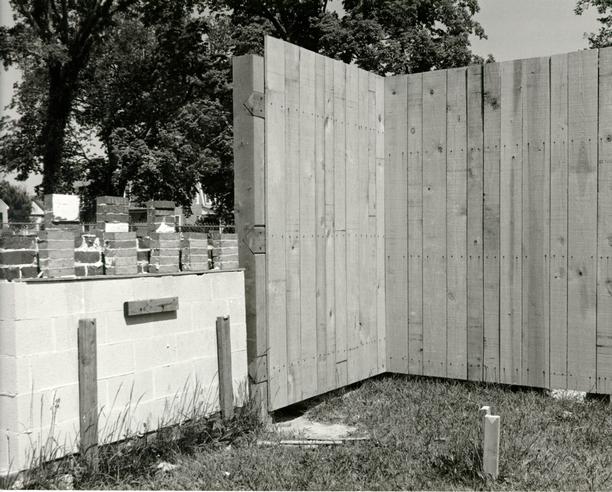
From very early in the design stage, the west exercise yard was intended to conceal modern conveniences (Fig. 291). To the handicapped ramp and the air intake/exhaust grilles was added another necessary aspect of modern life: a standpipe hydrant. This latter element was positioned next to the pedestrian gate for easy access. Because the standpipe was incorrectly located, the fence post locations were shifted slightly so that it would not interfere with the gate. The standpipe was later moved to its correct location, but the fence remained altered. Vehicular access to the yard was provided by a bivalve gate designed to be concealed on the exterior.
Gate hardware for the fences consists of strap hinges, hasps, staples and padlocks. The committee first selected as the hinge prototype the form of the Archibald-Blair smokehouse enlarged to the scale of the Mt. Airy stable door hinges. This
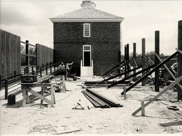 Figure 291
West exercise yard with handicapped access ramp. (CWF 85-TCM-1054-15s)
291
prototype later changed to strap hinges from the Lancaster County Jail. It was felt that a full size prototype was better than the combination to two different ones. The hasp and staples were modelled on those at the Cherry Walk smokehouse, whose upside-down middle hinge, so turned for security, also served as the prototype for the fence gates' middle hinges. At present, temporary padlocks secure the fence gates, until proper locks arrive from the Deane Forge shop. One of these padlocks will be based on the large lock from the Williamsburg Gaol (unstratified but similar to a ca. 1770-80 example in Artifacts of Colonial America) and the other on the Littletown Quarter (Kingsmill), 1750-70.
CONSTRUCTION
Problems seemed to plague the construction of the new fence from the very beginning.38 Setting the posts proved to be the first problem. The contractor's postholes were both too narrow and too shallow (Fig. 292). In addition, postholes in the west yard encountered water pipes and the nineteenth-century steam tunnel. The solution here was to dig deeper, wider holes and to place in them a small amount of concrete. However before this was carried out, a more serious problem necessitated resetting many of the posts. The pales, it turned out, arrived at the site and were too thin, ranging from ¾" to 7/8". Excessive warping was feared, especially for the 1' 7" top extended above the top rail. Rather than delaying the project
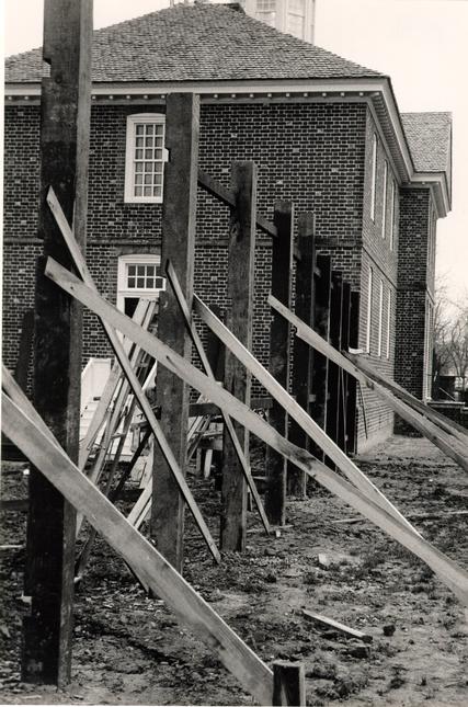 Figure 292
Exercise yard fence construction (CWF 85-TCM-326-8)
292
while additional lumber was milled, a quicker solution called for raising the total height of the fence, increasing the distance between the rails and decreasing the height of the unsecured pales above the top rail. This was possible because the posts and the pales had additional length that would otherwise be trimmed off. Raising the fence also solved, to some extent, the visual intrusion of the 12' gallery wall when viewing the front of the hospital. As a result, the committee decided to raise the fence 1' 3" for a total height of 11' 10". The posts were raised to an 11' 8" level, with the pales extending 12' above the top rail. This entailed replacing three new posts, which had already been cut for rails, and resetting thirteen of them at a higher level (Figs. 293-297).39
One final complication surfaced during the fence construction, when it was recognized that the grade not only sloped north-to-south in each yard, but also inward from each corner of the fence on the south side. Research of documented fences determined that the most historically correct solution among several options was to adapt the fence to its site so that in elevation it matched the profile of the terrain. In other words, the proportions of each fence panel are identical, with the rails parallel to grade and the pales a uniform distance off the ground.40 The changes in grade were slight: 5 ½" on the west elevation; 8 ½" on the south elevation of the west yard; 6 ½" on the south elevation of the east yard; and 8" on the east elevation.
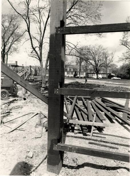 Figure 293
Construction of exercise yard fence, showing rail placement on corner posts. (CWF 85-TCM-1054-21s)
 Figure 294
Construction of exercise yard fence. (CWF 85-TCM-1207-11s)
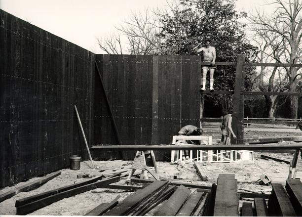 Figure 295
Construction of exercise yard fence. (CWF 85-TCM-325-18)
 Figure 296
Construction of exercise yard fence. (CWF 85-TCM-325-11s)
 Figure 297
Exercise fence construction crew. (CWF-85-TCM-1207, 15s)
With the completion of the fence gates in June 1985, the Public Hospital was effectively finished - 100 years to the month since its destruction (Figs. 298-301).
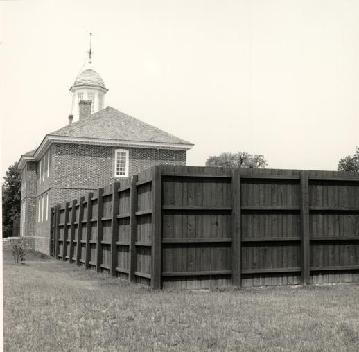 Figure 298
Exterior view of completed exercise yard fence. (CWF 86-FD-5731, 9s)
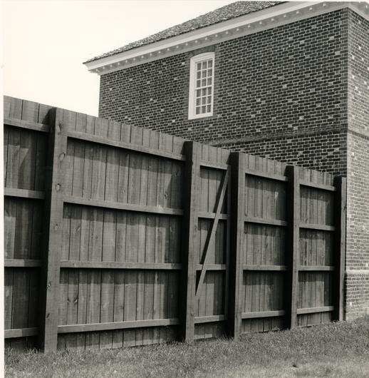 Figure 299
Exercise yard fence showing pedestrian gate.
 Figure 300
View of the east exercise yard from the Hospital passage. (CWF 86-FD-5731, 1s)
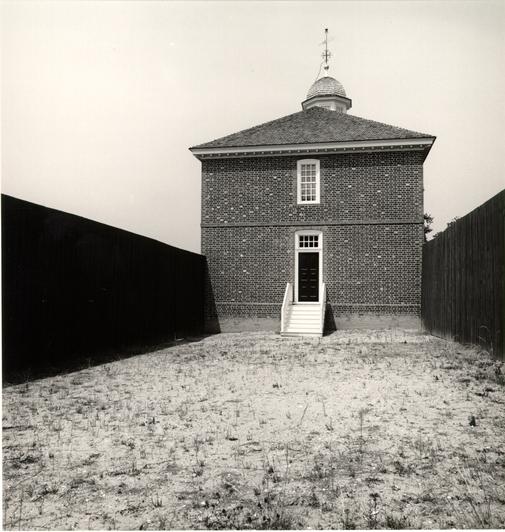 Figure 301
The barren structure-less east exercise yard. (CWF 86-FD-5731, 3s)
CHAPTER XXVIII
NOTES
CHAPTER XXIX
GROUNDS
DESCRIPTION
The hospital grounds to the north of the building contain a historic marl walk on axis with the front doors and modern diagonal brick walks (Fig. 302). To the south is a gravel-bituminous roadway connecting Henry and Nassau Streets.
DOCUMENTATION
Archaeological excavations north of the hospital were confined to the porch area immediately in front of the building. Consequently, little is known about the grounds north of the original building. Written documentation mentions the following outbuildings prior to 1800: well, 1773; smokehouse, 1774; house for straw, 1774; stable, by 1786; unidentified "out-houses," 1790; granary, 1793; and three necessary houses, 1794. Vegetable gardens were also located somewhere on the grounds from the very beginning. Although archaeology did not document any eighteenth-century outbuildings, later nineteenth-century insurance plats indicate, as one might suspect that the subservient outbuildings were located south of the hospital.1 The Design Review Committee had decided to consider any fences and outbuildings as a later phase of reconstruction. However, the reality of the Gallery's location precluded plans for future
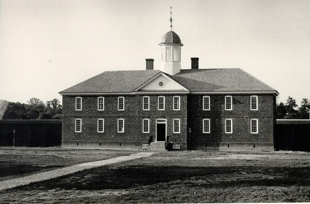 Figure 302
North side of the Hospital with its axial marl walk. (CWF 85-WW-408, 9s)
299
reconstructions. A discussion of these outbuildings is contained in the history section of this report.
Besides lot fences, which are discussed in the exercise yard chapter, an axial marl walk was the only historic landscape feature thought to have been north of the building at its completion in 1773 or shortly thereafter. A report by garden historian Peter Martin, summarizing his analysis of the probable landscaping at the hospital, stated that the north grounds probably consisted of an enclosure of grass with an axial path.2 The Simcoe Map, ca. 1781 (Fig. 24), also seems to confirm this, showing an opening in a perimeter fence at the location of an axial walk. Based on this information, an axial marl walk was included in the site plan, intended to be in historical contrast to the curving brick walks. A stroke of luck came in the summer of 1984 when an incorrectly placed storm drain revealed traces of an eighteenth-century axial marl walk. This evidence seemed to confirm both a north-south, as well as an east-west walkway, dating from the late eighteenth century to the nineteenth century.3
DESIGN
Major aspects of the site plan were first designed by Don Parker, Director of Landscape Architecture, in July 1981. Revisions occurred in June 1982 and November 1984. These revisions principally concerned the walks and drives, the question of new and existing plantings, lighting, and signage.
300Modern walks around the building evolved over a long period. The initial scheme called for a combination gravel and sod saver walk in front of the hospital to accommodate the possible use of vehicles at the front door. This vehicular access was moved to the south and became a two-shot bituminous roadway. The "meandering" marl walks which led from the corners on Francis Street to a brick pad at the front door, evolved into straight walks of brick and, eventually, into curving brick walks (Figs. 303 - 305). While the "meandering" walks were felt to be too "romantic," their straight forms were eventually softened with curves. Marl was used for the axial walk to distinguish it from the modern brick walks. Modern walkway materials were considered with regard to maintenance, distinction from the authentic walk and ease of access by the handicapped. Concerns for the handicapped and for maintenance of the hospital interior resulted in a decision for brick rather than marl or gravel. Additional sections of walk included a connector from the bus stop, a connector to the south side of the west yard and one around the east yard of the building.
Lights and signs were designed for their minimum effect, and their numbers were kept as low as possible.
From early in the project the Design Review Committee decided that the north grounds should have only the barest and most necessary landscape treatment. Without any hard evidence of what the grounds looked like in the 1770s, the best approach was to do nothing. By attrition the total number of trees on the
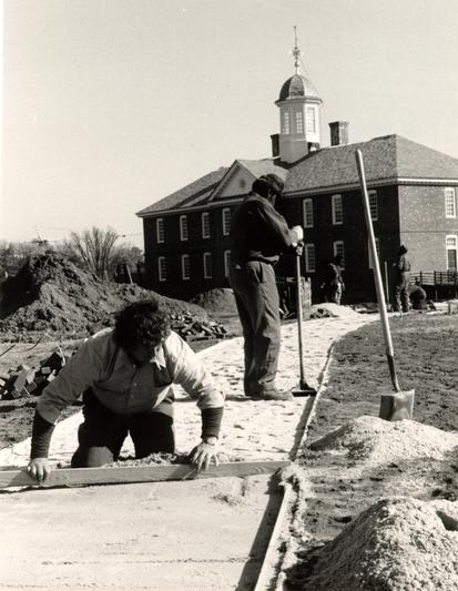 Figure 303
Construction of brick walks. (CWF 85-WJG-480-37)
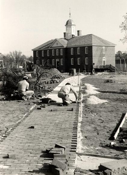 Figure 304
Construction of brick walks. (CWF 85-WJG-479-11A)
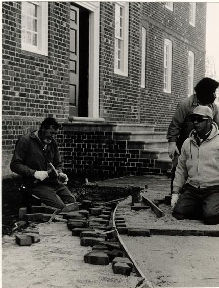 Figure 305
Construction of brick walks, Harry Flythe (L) and Jim Shipley (R). CWF 85-TCM-327-23A)
301
site became fewer. Additional trees, such as crepe myrtle, were removed as inappropriately ornamental and, a sickly looking cedar was taken down to provide a clear view of the building. While the magnolias on the site might not be appropriate for the period, they were mature shade trees and were retained to enhance the site and because they provide a link with Eastern State's use of the property. The only upon new plantings were intended for the south and west sides of the Gallery wall.
After the building opened, a need arose for some sort of seating near the front steps. This came about because the front stairs were being used by visitors as a place to sit and rest. The solution was to design a number of boxes and a tub, representing supplies that had arrived at the hospital (Fig. 306). The boxes were designed after a number of documented examples.4 The Design Review Committee acknowledged the fact that, historically, supplies would most likely have been delivered to the south side, where the cellar bulkhead is located. The suggestion of using a John Prentis and Company hallmark is based on his account of furnishing supplies to the hospital in 1773.5
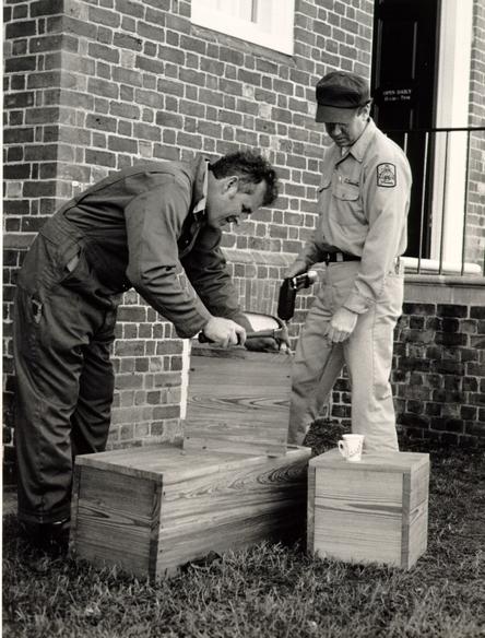 Figure 306
Eighteenth-century style packing boxes are assembled and secured in front of the Hospital to serve as seats. Tony Meyers (left) and Ernie Clements. (CWF 86-EAC-94-11s)
CHAPTER XXIX
NOTES
CHAPTER XXX
INTERIOR
DESCRIPTION
That part of the Public Hospital interior devoted to historical interpretation is the east wing of the first floor. This consists of a recreated eighteenth-century longitudinal passage with six cell doors; a northwest cell representing the late eighteenth-century period; a north central cell space used as a modern viewing area; a northeast cell representing the circa 1845 period; and a modern exhibit room occupying the space of three cells south of the passage.
DOCUMENTATION
The hospital specified by Robert Smith and the hospital constructed by Benjamin Powell were not exactly the same. For instance, the overall dimensions, as determined by archaeology, were 100' 4" x 32' 5" below the water table; Robert Smith's dimensions were 100' x 32' 5". Wall thicknesses also varied. Archaeology confirmed that the exterior walls were 24" thick (Robert Smith: 19"). The 24' wide central pavilion, projecting 3', was the same.1 This discrepancy was easily explained. On December 16, 1771, the directors of the hospital decided to increase the thickness of the walls by half a brick.2 Another discrepancy, for which there is no explanation, is the difference in floor/ceiling levels. In this case, a careful analysis of the 304 two historic photographs, combined with the archaeologically established horizontal dimensions and the cellar floor level, indicated that the cellar was about 7' 6" in height (RS 8'); the first floor 11' (RS 10') and the second floor 10' 6" (RS 9' 6").3
Archaeological excavations confirmed the hospital plan described by Robert Smith and recorded in the Court of Directors' minutes. In December of 1972 Paul Buchanan and James F. Waite's interpretation of the excavated foundations were set forth in Waite's report, "Architectural Notes on First Preliminary Drawings:"
The plan of the building, verified by the extant foundations, followed Smith's intentions exactly; a long east-west rectangle with a center projection front and rear. [PHOTO OF FOUNDATION EXCAVATION DRAWING] Each wing contained a center east-west Passage with three cells on either side. At foundation level the exterior walls are roughly 1' 11" thick, the side walls of the center projections (which continue north-south through the building) are about 1' 6" thick the Passage walls are 1'1" thick, and the division walls between the Cells are 9" thick. Remains of an east-west wall lining with the north Passage walls have been found in the center pavilion. There are no indications of a basement wall lining with the south Passage walls here, however, and since the plan as understood seem to require a wall in this location, it must be assumed that the first and second floor walls here [were] timber framed and supported by a beam, or perhaps trussed.
Foundations for two original chimneys exist, much reworked from their original form. These occur to the east and west of the original basement space, projecting into the Cells south of the Passages. The foundations of the chimneys also project north into the Passages. This is the builder's attempt to locate the chimneys as close to the ridge of the building as possible, still leaving space for doorways between the Hall and the Passages.
305The length of the west chimney foundation to the south is seen as the builder's method of providing support for a second floor fireplace, since a fireplace on the first floor would certainly have occurred over the relieving arch in the basement, fragmentary remains of which have been discovered. In the masonry of the east chimney foundations are indications of a large fireplace, projecting into the basement room.
The architect's description indicates that there was a complete basement story under the building. It was discovered, however, that the structure was completed with a basement under the center portion only, and that there was crawl space only under both wings. The basement space, divided into Kitchen, Storeroom and Stair Passage, was reached at the north-west corner of the Passage by an interior stair, and at the south-west corner of the Kitchen by a bulkhead entrance on the south wall. There are sockets in the brick for a stair of reasonable width and slope, descending against the west wall to a landing in the corner, and having its last several steps against the north wall..
The foundations of the south walls of the Passages exist more or less complete, whereas their counterparts on the north side of the Passages were destroyed by the insertion of a brick steam tunnel roughly along the east-west axis of the building immediately after the fire of 1885.
Three rooms were dug out of the crawl space under the first floor cells around the end of the eighteenth century. These are the full-depth spaces to the northwest, southwest, and southeast of the original basement. The existing walls were underpinned and the floors dug out to approximately the level of the original basement floor.
The top of the existing foundation walls of the hospital indicate an arbitrary level to which they were pulled down and robbed immediately after the fire.
There is no evidence that there was access to the crawl spaces.
At the time of the excavation brick flooring existed in the entire basement space, except where it was distributed by the steam tunnel and where it had been robbed. The color and small size of the bricks indicated that it was not an original floor, although there may have been a brick floor earlier, perhaps taken up and relaid due to the dampness which plagued 306 the hospital from the beginning. There are indications that no brick flooring existed in the original basement.4
INTERPRETIVE CONCEPTS
Consideration of a reconstructed interior and an interpretation of early mental health care only came about when it was decided that the decorative arts gallery would be a building separate from the Public Hospital. When interpretive space was first discussed by the Program Planning and Review Committee in September 1980, there were no clear-cut ideas of where in the building the exhibit area would be located; the basement, entered through an exterior bulkhead, seemed to be a strong favorite.5 By April of the following year a subcommittee of the Program Planning and Review Committee had determined that the Public Hospital exhibit would be established in the east wing of the building. By June it has further established a plan that featured visitors coming into a reconstructed passage from the east door of the hospital. From a northeast orientation cell they proceeded into two reconstructed cells on the north side and then into an open exhibit room on the opposite side of the passage taking the space of three cells; visitors exited out through the east door. The committee also discussed interpretation concepts, separating them into three main categories: 1) establishment/founders and the building; 2) treatment/doctors and patients; and 3) contribution. Interpreting the spaces could be accomplished by costumed interpreters, by uncostumed interpreters, or by a static 307 exhibit.6 Unfortunately, this plan came to represent the maximum reconstructed interior space considered by the committee.7 By this decision, the related decisions calling for a first floor lobby entrance to the attached gallery and for modern office space on the second floor, the question of providing more space for the interpretation of mental illness and for reconstructing the hospital's central pavilion entry stairhall and keeper's quarters became moot.
From the summer of 1981 onward, the historical interpretation of the interior was spearheaded by historian Shomer Zwelling and a new interpretation committee was formed at the end of that year.8 One of the most significant decisions made at the first committee meeting was the decision to interpret the Public Hospital past the colonial period and to include much of the nineteenth century. Based on Zwelling's initial research and recommendations, the Interpretation Committee was able to make some definite concept and design decisions by the fall of 1982. Zwelling proposed a central theme around which the research and exhibit developed:
The interpretive time frame was established as 1773 to 1885, the original building's lifespan. Within this period three phases were chosen for the exhibit: 1773-1835, the Age of Restraint; 1836-1862, the Moral Management Era; and 1862-1885, the Custodial Care Regime. For the two cells the "touch down" dates were 1773 and 1845, providing a great contrast in physical setting and theories of treatment.In determining a theme for the exhibit it is important on the one hand that we be as straight forward and concise as possible and on the other that we remain mindful of the central issues addressed by contemporary American historians. A historical perspective will be particularly important in this instance because our exhibit will be essentially a social history story rather than an exhibit on fine arts, architecture or folk traditions.
Among historians the central theme of our day concerns the matter of change over time. During the past few years, this theme has begun to effect the interpretation of history here at Colonial 308 Williamsburg. We can observe it in the plans for Carter's Grove, the interpretation of the Afro-American experience, the Core Curriculum for Interpreters, and the York County Project. In a significant way, each of these projects addresses the issue of change. So too, I think, the exhibit on the Public Hospital should address the subject of change over time, specifically the matter of change in mental health care--therapy--over time. After all, therapy or cure is at the heart of the hospital. Indeed, it was in part because certain people believed that all cases of insanity were at the root somatic in nature that the hospital was founded. Since that day, the etiology of mental illness as well as the means, methods, and techniques of cure have been much debated topics. Not surprisingly, the proposed solutions have been manifold. Each phase in this debate reflected on the society as a whole and the hospital in dramatic ways. Finally, by concentrating on the questions surrounding therapy I think we will also be able to acknowledge other significant themes--founding, daily routine, people and physical expansion of the institution-- although hardly in depth or detail.9
DESIGN
Architectural research for the interior developed simultaneously with historical research for the interpretive cells and exhibit. Robert Smith's "Description" was not as significant for its details of interior finish as it was for an understanding of the building's plan., The building's 309 arrangement of space was carefully analyzed in terms of zones defined by function and circulation. Each zone, based on analogous examples, was believed to have a corresponding level of detail and finish. For example, the entry hall and the director's room might typically have had a panelled wainscot and plaster walls, while the passages and patients' cells would have had a less finished treatment. In other words, the smallest details, seemingly common and explicit, speak of meaning and inherent social values.10 This idea seems rather obvious, yet all too many early reconstructions failed to either recognize or reproduce this reality. This methodology became the framework in which the hospital's reconstructed interior spaces were researched and designed. Buildings historically relevant to the hospital, such as jails, almshouses, hospitals and asylums, and a wide assortment of written records concerning the same formed the major thrust of documentary research.
CHAPTER XXX
NOTES
CHAPTER XXXI
EIGHTEENTH-CENTURY PASSAGE AND CELL
One of the first questions concerning the passage and the reconstructed interior was the mystery of the staircases. In June 1790 the directors "Ordered that Mr. Andrews, Mr. Southall, and Mr. Travis be appointed a Committee to contract with proper Workmen for erecting a Stair-case at each end of the hospital, and also to have fixed in the passage below, two Iron Grate Doors, for the purpose of admitting air into the Cells, in such a manner as they shall think best."1 If it were not for the reference to "the passage below," this might be taken for exterior stairs. A first floor location seems more likely because a secondary access to the second floor would enable patients to be taken directly out doors without having to pass through the main hall. The configuration of such a staircase is unknown but it must have been awkward in such a narrow passage and it probably displaced a cell door. A reference in October the same year to "working in a door frame" might be evidence for this latter supposition.2 An 1804 reference to whitewashing three stairways at the hospital is further evidence that they were indeed built and that they were interior stairs.3 Without further detailed information and because of the late date, the Design Review Committee decided not to attempt a reconstruction of the stairs.
312The question of finish for the passage led to a complex analysis of wall and ceiling finish for the entire building. Edward Chappell's theory of hierarchical finish suggested three most likely categories of finish within the range of possibilities at the hospital:
Surely, the most public rooms, the hall, and the directors' meeting room would fall in category 1, but what about the more private passages and cellar, and the most private spaces of all, the patient's cells?4
- (1)Fully plastered walls and ceilings. The superior level of finish is confined largely to rooms that were directly related to the activities of affluent people. Such spaces could be the property of merchants and/or gentry (houses, offices), or they could be public property (courthouses, churches), but the level of finish implied some aspect of upper-class interaction. Choice of finish was a selective process, however, and consistency of wall treatment was not a condition of good building. As a result, the brickwork and framing of the tower entry at Bruton could be left exposed and attic rooms which apparently contained domestic functions at the Tayloe House remain largely unfinished.
- (2)Plastered walls and exposed finished ceiling framing. This might be called a middle level of finish and seems to characterize store sales rooms and the principal rooms in houses of moderately well-to-do middle-class Virginians.
- (3)Unplastered walls and exposed unfinished ceiling framing, all possibly whitewashed. The lower level of finish was standard in work buildings, slave houses, and storage and/or servant's rooms in large houses. It is assumed that this was also a common condition in houses of as much as half of the eighteenth-century white population, but our hypotheses in this area are based, for the most part, on circumstantial evidence.
Among the many vague accounts of plasterwork and whitewashing there is a crucial one that helped decide the issue. 313 Humphrey Harwood noted in his ledger in 1776: "To Larthing & plastering cealing of hospital by Agreement @ 1/6 pr yd 21.-4.6."5 This is one of the most significant yet mysterious references to interior finish at the hospital. Its mystery lies in the fact that, in September 1772, the hospital directors examined the building and declared it finished "according to Agreement" with builder Benjamin Powell. That Harwood's work included both lath and plaster, that it covered a considerable amount of space (284 square yards), and that the building was only three years old, indicates that it was not repair work but a new ceiling finish.
Using as a measure 283 square yards of ceiling area, the possible ceiling combinations could be many. There is, however, a probable explanation based on the most likely hierarchical scheme. If we can assume that Powell's contract absolved him of finishing any ceilings in 1773, Harwood undertook the ceiling finish of appropriate spaces three years later. If the ceilings in the hall, keeper's quarters, directors' room and passages on both floors had been plastered, approximately 221 square yards would be represented. The remaining yardage could be accounted for by including the cellar rooms or about the space of five cells. A subsequent account of Harwood's in June 1766 to repairing the plaster and whitewashing four rooms and two passages lends further evidence that the passage contained a whitewashed plaster finish.6 Comparative examples of a specific nature are scarce and do not fall into any sort of neat pattern 314 of finish. For example, the 1753 Spotsylvania County prison had cells with plaster ceilings. This is just as surprising as an account of an English asylum that in 1844 still featured cells without plaster. Bethlehem and St. Luke's Hospitals in London in the 1780s are described as having cells that were boarded and wainscoted, yet the New York Hospital had whitewashed (brick wall) cells in 1811 or earlier. Consequently, the committee chose for the passage finish a plastered ceiling and walls and for the cells unplastered brickwork and an exposed joist ceiling. This decision relies to a great extent on the ceiling plaster analysis, but it also reinforces a systematic regional view of hierarchical finish.
All parts of the reconstructed interior fell under the systematic interpretation of spaces and details. The end passage doors, for example, were redesigned in a more meaningful manner according to this system.7 These had initially been designed as panelled doors, based on Benjamin Powell's reference in his contract. In their relationship to a space where a concern for security was important, it was argued that the end passage doors were analogous to other known situations that called for a double thick door.8 Commonly these doors featured a panelled exterior face and a sheathed interior face with diagonal-set flush boards. Examples are found at Mt. Airy; the Farish Print Shop in Port Royal, Virginia; Montpelier, Maryland; and examples in Kentucky.9 The actual working drawings and execution of the door were based on a door at the Clerk's Office, Northampton County, Eastville, 315 Virginia.10 Because the board widths on this example were thought to be too narrow, reflecting a Federal period construction, an 8"-12" range was specified, based on examples of eighteenth-century board widths.11
The same system of differentiated finish applied to door trim in the passage. For the passage-to-lobby door just described, the lobby side casing features a cyma backband and a beaded corner with a full (3/4) bead whereas the passage side has a cyma backband and a half bead on the corner. In descending order the east door trim changes from a three-part, double cyma, beaded corner on the exterior of the east passage door, to a two-part, backband-beaded corner (with half bead) on the passage side of the same door, to a one-part beaded corner on the passage side of the eighteenth-century cell door, and finally to a completely plain casing on the patient side of the cell door.12 The difference in the inner/outer cell door trim is based on an example at Shirley where there is a kitchen/passage interior door frame relationship.13
The Shirley kitchen provided an example for a similar difference in interior/exterior window trim. Accordingly, at the hospital the outer side has a double cyma and beaded corner trim while the cell side has a plain trim with no molding except for an applied beaded sash stop.14
Baseboards for the passage and eighteenth-century cell were based on a Blandfield kitchen prototype measuring 7/8" x 4 ¾" with a half bead.15 This element, and all other wooden 316 members of the eighteenth-century passage and cell, were left in a natural finish with no paint or sealant, as is the trim in many eighteenth-century secondary spaces, including the Blandfield kitchen.
Fieldwork for the Agricultural Buildings Project influenced the bond and quality of brickwork in the eighteenth-century cell. Analogous lower status spaces with exposed brickwork commonly feature English bond struck along the bottom of the joint. The same brick and mortar used for the exterior was used also on the interior, including the use of random glazed brick.
Floor board sizes, 4 ¾" - 8 ½", were based specifically on those at the Ludwell-Paradise House, similar also to measured examples at Shirley. The nailing pattern for these was set at 17" centers, based on comparative examples of joist spacing at the Wythe House, the Ludwell-Paradise House, Berkeley, Shirley, and Carter's Grove.16
Wooden lintels for windows were found to be either one or two bricks high. Due to the placement of the hasp and staple of the window grate, a two course high lintel was chosen; examples are found at the Wythe House (cellar, east side) and also at Shirley.
Some of the Public Hospital doors were originally specified to be reflections of both their function and their location in the building. Smith only went so far as to specify a thickness, 1 ½" plank, but Benjamin Powell's contract specified 317 that "the outward Doors and those to the Middle Rooms to be panelled an the others strong batten Doors."17 The batten doors were those to the cells, by necessity strong, and by location, plain. Had it not been for a much later reference, the design of these doors could have followed several options. The clue came from an 1833 account for extending the size of the detached 1821 and 1825 buildings that had been constructed much like advance flankers to the north of the original building. The 1833 specifications called for "…one Iron grate over each door, the doors to be made of seasoned inch and a quarter pitch pine, all heart and free from bad knots and shakes, and put together with three strong batterns of the same, to be hung by strong hook and eye hinges, and secured by such a lock and hasp as the doors of the old houses have on them."18 The reference to "old houses" no doubt refers to the 1831 and 182'5 buildings, but there exists the likelihood that specific details for these buildings had, in turn, been modelled on the original building. In light of this, the cell doors were designed as vertical boards with three inner bevelled battens clinched with T-head nails, a rather predictable form (Fig. 307 - 308).
The cell door width was based on the 3' 0" example at the Alexandria Almshouse; the Pennsylvania Hospital's cellar cells featured 2' 9" wide cell doors. Cell door heights were set at 6' 4", based on prerestoration doors at the Williamsburg Gaol, with heights of 6', 6' 4" and 6' 6".19
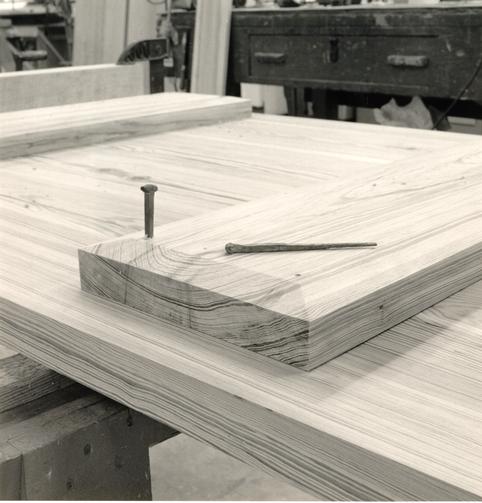 Figure 307
Eighteenth-century cell door battens are secured with wrought iron T-head nails which are clinched on the passage face side. (CWF 84-FD-2352, 1-12s, 11)
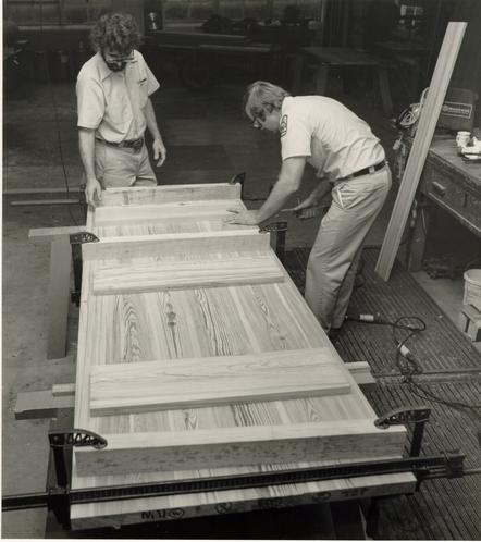 Figure 308
Tim Edwards (left) and Larry Heath assemble the cell doors. (CWF 84-FD-2352-1-12s, 4)
A more interesting question concerned the swing of the cell doors: did they swing in or out? This was debated from various points of logic. An outward swinging door allowed for a quick observation of a patient and it also prevented the door from being barricaded from within. outward swinging doors also required standard locks mounted on the passage side. Putting aside all rationales using twentieth-century logic, the question was examined according to eighteenth-century concepts. Buildings of high-style or public function generally featured inward swinging doors, while inferior structures, such as outbuildings, had either outward or inward swinging doors. Ultimately, the evidence from prison cell doors at Newgate, Berwick-upon-Tweed and Warwich County, and nineteenth-century cells at the Pennsylvania Hospital led to a design with outward swinging doors (Fig. 309).20
The placement of the cell doors in a symmetrical fashion within the passage was based on common and traditional patterns. The actual pattern of hanging doors was less apparent. In a wide range of examples, the only system appeared to be that doors opposite each other are generally hinged on reverse sides (left hand, right hand), so that they swing either in or out in a mirror image fashion. This scheme led to three left-handed doors facing three right-handed doors. There seems to be no norm for single exterior doors to be left or right handed.
Included in Robert Smith's "Description" were iron grates for the cell windows. There is no doubt as to their
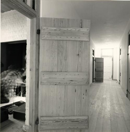 Figure 309
The outward-swinging cell door hung on strap hinges and showing the clinched ends of the sliding bolt and hasp. (CWF 85-FD-35-6)
319
appearance or placement; as Smith's two sketches of the same were copied into the directors' minutes book (Figs. 310 - 311). The door grates, on the other hand, were not described by Smith, sketched in the minutes, or mentioned in Powell's contract. Powell's contract only referred to the fact that he was not responsible for furnishing "the Grates and such other things as are usually imported from England… ."21 The grates were indeed ordered, though not from England, and it is in this order that the small grates, presumably for cell ventilation, are mentioned. Hospital director Robert Carter decided, not surprisingly, to order these grates from his own Baltimore Iron Works.22 Carter wrote to Clement Brooke of the Baltimore Iron Works in 1771; their exchange is as follows:
April 22, 1771Clement Brooke to Robert Carter
Robert Carter to Clement Brooke . . . I send 2 patterns of wood to shew the sizes of grates wanted for an hospital now building here for the reception of Lunaticks 24 of the larger size are wanted 24 of the other size are wanted, both sizes to be made of wroght iron and 48 hoocks - the directors who superintend the building expect that you signify to me the price you ask for the same, also the time you require to finish the said work--"
June 3, 1771 …We can make the Grates agreeable to the paterns and will Acquaint you by the next Trip when they can be done as likewise of the price.
Clement Brook to Robert Carter
October 2, 1771 …I have sent down all the Iron Grates & Hooks by the Bearer Capt. Sanders they weigh 2664 lb. @ 8d. isFigure 310
Plan section of the window grate placement copied into the Directors' Minute Book from Robert Smith's "Description." (CWF 81-2770)Figure 311
Elevation sketch of the interior window grate copied into the Directors' Minute Book from Robert Smith's "Description." (CWF 81-2768) 320 £88..16..- which I have charg'd to your Private Accot.23
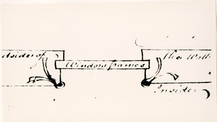
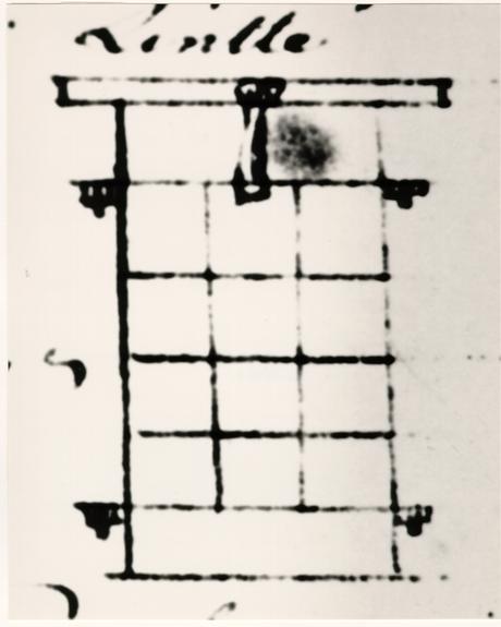
Robert Carter's Account Book, 1759-1775 May 25, 1772 Dr. Mr. Jacob Bruce of Wmsburg. to Cash received of Robt. Carter Nicholas Treasurer, for Sundry Iron Grates for the use of the Colony £90-5-6.24Research of the Baltimore Iron Works produced no significant information regarding the order. It is entirely possible that Robert Smith used as his prototype window grates at the Pennsylvania Hospital, known now only through written records.25
The twenty-four small grates, by deduction, had to be associated with the cell doors. But were they located in the door itself or over it as a transom? Historic examples were found for each option.26 Grates in a door were used for both observation and to distribute food. Grates over a door were used for ventilation. Amore common arrangement for the former situation is a solid hinged or sliding shutter that can be opened from the exterior. By the second quarter of the nineteenth century, treatises on Moral Management advocated observation "wickets" in "apartment" doors. The only specific reference to grates at the Public Hospital is the 1833 specification for additions, quoted in part earlier, that mentions "one Iron grate over each door." The function of these grates was undoubtedly ventilation. The absence of an opening for observation is significant because by this date the leading authorities on asylum management were advocating cell door wickets. A possible 321 explanation is that the grates over the doors were modelled on prototypes already existing at the hospital, just as the method of securing the doors had been. The most relevant comparison is with the Pennsylvania Hospital. There, the cells had an opening above the door, as well as a shuttered "hole" in the door. Other examples include St. Luke's Hospital in London, with an opening over the door and Bethlehem Hospital which featured both types. Eighteenth-century jails in England, seen in photographs, had openings in both places. If we turn to another Robert Smith design, the Walnut Street Jail, we see that there were louvered transoms above the cell doors. In summary, the ventilating grate seemed historically more common and was approved for the six cell doors of the passage (Fig. 312).
The Committee considered two basic types of construction for the window and transom grates. Examples of eighteenth- and early nineteenth-century grates revealed either flat pieces riveted together or square vertical members that passed through flat horizontal members. Examples of the former include a window from the Northampton County Jail, Eastville, Virginia (Fig. 313); an iron grille door and a window grate from the First Bank of the U. S., Philadelphia; and a door grate from Newgate Prison, London. Examples of the second type include a window from the Lancaster County Jail, Lancaster, Virginia; a window grate from the Prince Edward County Jail, Worsham, Virginia; window grates from the Williamsburg Jail (possibly mid-nineteenth century); and the County Jail, Warwick, England.
 Figure 312
View of the passage with cell doors and east and exterior door. (CWF 86-FD-5730, 9s)
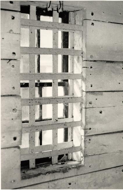 Figure 313
Northampton County Jail, interior window bars. (CWF 83-1232s, TCM)
322
Unfortunately, it is not known what the Pennsylvania Hospital grates were like. Upon a careful analysis of Robert Smith's elevation sketch of the window grate, the committee decided that the square, vertical/flat, horizontal treatment with the verticals set on a diagonal more closely corresponded with the Smith sketch (Figs. 314 - 317). One final question of construction involved the method of setting the transom grate. Was the grate framed as a rectangle and nailed into place or did its vertical members extend into the masonry? Based on the form of the sketched hospital window grate, the former method was adopted.
An unexpected interface problem concerning the eighteenth-century cell caused one feature to be redesigned. Because the structural drawings and, in fact, the structure had preceded the interior design by so much time, the finished ceiling in the eighteenth-century cell could not exceed 10'. This meant that the 11' ceiling joists would fall below the window level. This posed a real dilemma. Shortened joists would present unauthentic detail and a plaster ceiling would alter the long debated system of finish. The latter choice would also necessitate plaster on the walls, which would further alter the system of finish. The educational value of the cell finish was felt to be just as important as historically correct and authentically executed detail. The solution that offered an alternative level of finish yet is still consistent with the previous decisions was a flush board ceiling (Fig. 318).
 Figure 314
Ken Swartz (left) and Peter Ross punch holes in the transom gate bars. (CWF 84-DS-2236-8s)
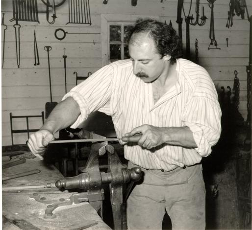 Figure 315
Peter Ross is shown here filing the tenon for the transom grate. (CWF 84-DS-2237-5s)
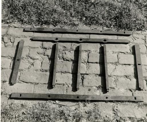 Figure 316
The dis-assembled parts of one transom grate. (CWF 84-DS-2238-6s)
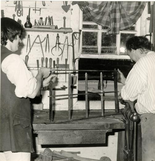 Figure 317
Ken Swartz (left) and Peter Ross assemble a transom grate. (CWF 84-DS-2237-9s)
 Figure 318
Ernie Clements shown with the flush board ceiling. (CWF 84-FD-2618-10)
323
Blandfield offered a prime example. There in the cellar was a room apparently used as a living space, most likely by servants, that featured a sheathed ceiling of random width hand-planed boards fastened with wrought nails, whitewashed brick walls and a dirt floor.27 Based on the example of a sheathed ceiling at the Lancaster Jail, the ceiling boards stop short of the brick walls.
CHAPTER XXXI
NOTES
CHAPTER XXXII
NINETEENTH-CENTURY CELLS
Research for the design of the nineteenth-century "apartment" was not nearly as difficult as that for the first period cell. If there was a problem with the later period, it was one of riches; there were many records from Eastern State Hospital's nineteenth-century era (past 1820) and for just about any other American asylum of the same era. Most importantly, many of these asylums are still standing with interiors hardly altered.
With the establishment of a specific second period interpretive date of 1845, the committee had three chronological options of Eastern State buildings to represent the space: the 1835 extensions of the 1821 and 1825 flanking buildings; the 1838-40 west wing and the third floor of the original building; or the 1842-44 east wing addition. The first option, the 1835 additions, represented a period in which some architectural details were still being modeled on earlier prototypes. The 1838-40 option represented a transitional period in which Moral Management ideas were implemented. The third option represented a period in which changes had already taken place. Option two was chosen for several reasons. First, there is the interesting notation by the hospital's Building Committee, recorded in the minutes of 1 June 1840, to change the batten doors that had first 327 been specified to paneled doors, which "would be neater in appearance… ."1 This suited the interpretive intention of representing in the second period cell the implementation of Moral Management ideas of administration and treatment. The second reason for selecting this option is the fact that these changes were implemented in the original building itself, on the third floor.
Exemplifying the richness of resource material is Western State Lunatic Asylum, later called Western State Hospital, in Staunton, Virginia. While other institutions were examined for their interior details, such as the Richmond Almshouse, St. Elizabeth's Hospital in Washington, D. C. and the South Carolina Lunatic Asylum in Columbia, Western State proved to be the perfect prototype. Although the original Western State Hospital has been adaptively reused as a medium security prison, its earliest buildings, from three periods, 1828, ca. 1838 and 1840, are virtually unaltered. It is also the only Virginia asylum established in the early nineteenth century.2
The three buildings examined at Western State mirror, to some extent, the rapidly implemented ideas of administration and treatment that affected the 1830s-40s buildings at Eastern State.3 The first building constructed between 1825-1828, like the Public Hospital, was designed by a well known architect from a distant city, William Small of Baltimore (Fig. 45).4 A general move toward Moral Management reforms can be seen in this first building, such as a higher degree of architectural finish and 328 some attempt at classification, but it is the following decade in which fully realized reforms are in evidence. In the second building, completed by 1838, an even higher level of cell finish is in evidence, as well as highly finished dayrooms and dining rooms (Fig. 47). Three years later the south building was completed, epitomizing in its design more of the prescribed facets of a progressive American asylum.
An immediate design dilemma became apparent in the second period cell. The nineteenth-century room was sandwiched, as it were, between two eighteenth-century areas: the exterior and the passage. Because of this, two of the most significant architectural aspects of the nineteenth-century period, important in the didactic use of a second period space, created interface problems. The door was the most obvious problem of the two. The passage represented an eighteenth-century space with six identical cell doors that opened outward into the passage. Equally important was the paneled door of the 1845 apartment and its wire mesh transom (Fig. 319). The different transoms precluded any sort of double sheathed door but because the Western State prototype had been inward swinging, the solution was to have two completely separate doors and transoms on opposite sides of the same jamb. Unfortunately, the other problem could not be as satisfactorily resolved. An important Moral Management detail of the nineteenth century was its cast iron sash that replaced the former jail-like bars (Figs. 46, 320). In this case, however, the eighteenth-century bars were
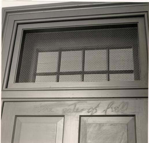 Figure 319
Reconstructed nineteenth-century panelled door and wire mesh transom based on Western State Hospital. (CWF 85-FD-32-2)
 Figure 320
Western State Hospital, Staunton, 1840s building showing exterior cast iron sash. (CWF 84-WJG-950s)
329
mounted on the interior while the nineteenth-century "bars" would have been on the exterior. Regrettably, because the exterior of the hospital represents its earliest appearance, a cast iron sash could not be installed.
Prior to establishing a specific date for the second period cell, a patient room in the original 1828 building at Western State had been recorded through measured drawings and photographs. This second floor room seemed to represent an average range of detail for a patient space in that building: batten doors with a solid wicket; symmetrical moldings on the door and window trim; a baseboard; and plastered walls and ceiling. once an 1845 date had been chosen for the second period cell, there were two possible prototypes at Western State, the 1830s north building and the 1840 south building. A second recording trip determined that the 1840 building came closest to fulfilling the interpretive philosophy. The difference between these two buildings were not great. Both featured single patient rooms of painted plaster, cast iron sash, baseboards and ventilating transoms of a tightly woven wire mesh. The principal difference was the door: the north building still featured batten doors with strap hinges, while the south building had paneled doors on butt hinges (Figs. 321 - 323). Because of the 1840 record that the directors had requested paneled doors at the Williamsburg Hospital, the north building was felt to be more appropriate. To be consistent, door and window trim were recorded from the same room from which the door details came.
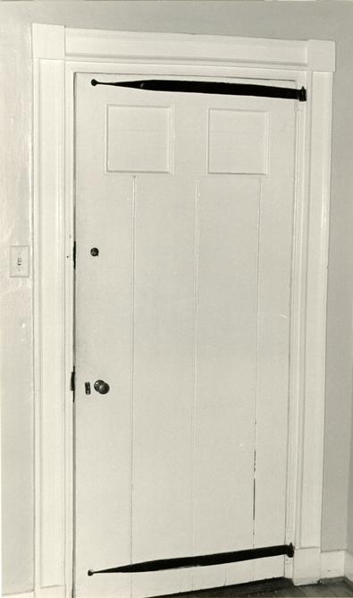 Figure 321
Western State Hospital, Staunton. Main Building with batten doors and strap hinges. (CWF 84-WJG-1890s)
 Figure 322
Western State Hospital, Staunton. Door from the 1840s South Building. (CWF 84-WJG-188, 1s)
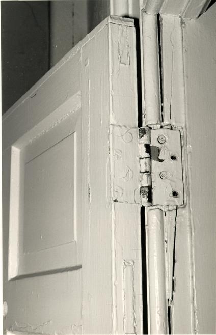 Figure 323
Western State Hospital, Staunton. Detail of hinge from the 1840s South Building. (CWF 84-WJG-1880s)
330
This latter decision was one of stylistic distinction. The north building featured interior door trim with symmetrical moldings and corner blocks and window trim of a cyma and bead combination. Curiously, the baseboards in both these buildings appeared to be painted stone with a bevelled top.5 Although closely contemporary in date, the south building had a much different trim. Here, both the door and window trim were a Greek Revival version of a colonial cyma and corner bead combination, with a very hefty bead (Fig. 324).
Working drawings for the interior, unlike those for the exterior, were produced in-house by James F. Waite. It was only during the initial process of producing these drawings that the committee realized that the hospital windows had been incorrectly detailed insofar as the construction of their frame as seen on the interior.6 Changes included setting the fixed upper sash within the window head; changing the lower sash stop from a beaded casing member to a beaded stop; cutting off part of the wooden sill to receive an applied bead and a casing member; widening the lower architrave to match the width of the sides and head; and eliminating a wooden stool in favor of an exposed brick sill. The decision to use hand-planed, unfinished woodwork in the eighteenth-century cell and passage necessitated rebuilding both the passage transom window and the cell window sash in edge grain pine to match the quality of other interior woodwork.7
Although the first painting reference does not occur until 1803, there are many references to whitewashing the
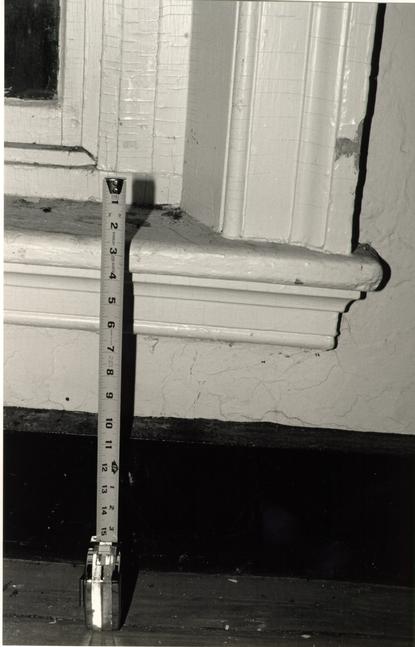 Figure 324
Western State Hospital, Staunton. Detail of window trim in the 1840s South Building. (CWF 84-WJG-1905s)
331
hospital interior, sometimes as frequently as every year. However, these give no clue as to the extent of coverage. Examples of service buildings, such as the kitchen at Blandfield, influenced the decision that the woodwork in the passage and in the first period cell would not be whitewashed or painted but left in a hand-planed, natural state. Whitewash covers the plaster surfaces in the passage and the exposed brick in the first period cell. Great attention was paid to the application so that it was not neat but rather sloppy, especially in the cell. (Fig. 325).
As one might expect, the second period "apartment" received paint on its door and window sash and their respective trim. The dark gray color was determined by examining paint chips from Western State Hospital and matching them to a Munsel chart.8 However, for the plaster walls and ceiling of the "apartment" there is an ironic historical twist in the scheme of finishes. Were it not for documented cost saving measures in 1840, the plaster in this reconstructed room would have been whitewashed. As instructed by the directors in that year, the interior of the new building was not whitewashed as specified in the contract. They considered it "unnecessary," saving the state $59.9 Despite what might seem to be an historical fluke, and not at all representative for the period, the committee felt that specific documentation outweighed the desire to create what was thought to be a general condition. As a result, the plaster was left unpainted.
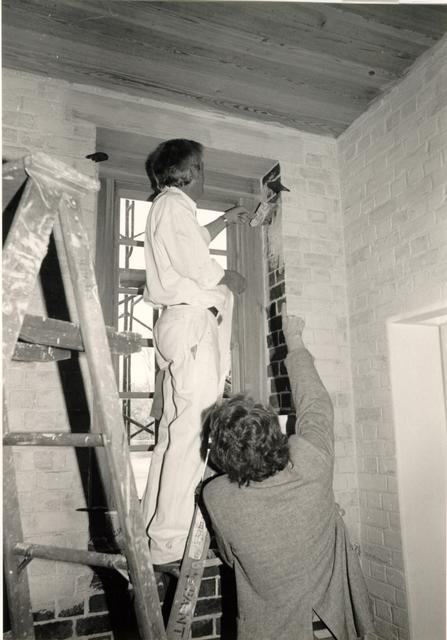 Figure 325
Edward A. Chappell directs painter John Hickman in the proper application of whitewashed brick in the eighteenth-century cell. (CWF 85-TCM-42-2A)
CHAPTER XXXII
NOTES
CHAPTER XXXIII
LUMBER
Specifying the right quality lumber for the hospital interior was of particular concern after the fiasco at the John Greenhow Store. In that restoration, inadequate specifications resulted in lumber that was glued-up from small strips, contained too much flat grain, was too narrow, had too much sapwood, and generally did not reproduce the appearance of a southern yellow heart pine. In an attempt to correct this and rebuild parts of the store, a contract supplier, Dewey Hudson of North Carolina, provided antique, re-sawn heart pine mixed with some new growth. The end result was, nevertheless, not entirely satisfactory.
For the hospital, the problem was not only one of quality, but also one of philosophy. Being sensitive to the early policy of using salvage material, the Department of Architectural Research in general and specifically the Design Review Committee sought to use new reproduction materials. There was also an associated problem, inherent in the use of antique wood, of a limitation in size and of possible damage from previous fasteners.
In the specifications, the term "edge grain" was defined to mean lumber with an average of at least 8 annual rings per inch across its face at each point in length, with annual 335 rings forming an angle of 45 degrees or more with the face, 20% 30% flat grain per board, and 50% of boards to be totally edge grain.
A potential source of virgin pine in Georgia became known while the reconstructed interior was still in a research and design stage. Tiresias, Inc., of Orangeburg, South Carolina, offered fresh lumber, cut and milled to order, that promised to match eighteenth-century material. An initial inspection trip had indicated that, at the very least, if the new wood was not forthcoming, Tiresias had on hand a much better supply of antique re-sawn heart pine than that supplied by Dewey Hudson. Armed with a tightly written set of quality specifications and a lumber summary list, two representatives inspected the newly cut lumber in June, 1984. The lumber looked good and, with the exception of two particular dimensional pieces, it appeared as if they could fill our order. An order was then placed with Tiresias with a delivery date of three weeks. Site inspections were scheduled when a third to a half the order had been milled and again before the entire order was shipped. For unexplained reasons, Tiresias broke off communications after placement of the order. Failing to respond to numerous letters, mail grams and telephone calls, Tiresias was informed that the contract was cancelled.
New efforts to find suitable lumber next focused on the previous supplier, Dewey Hudson. Little time passed before his particular shortcomings became known. Hudson could not supply very many of the specified sizes in new slow growth, dense grain 336 lumber, and he proposed filling out the rest of the order with old re-sawn lumber. Faced with a color match problem and the potential difficulty of mixing seasoned and kiln-dried lumber, the committee reluctantly decided to use re-sawn material entirely.
Before an order could be placed with Hudson, a much closer, more reasonably priced source was found. The E. T. Moore, Jr. Company in Richmond, specialists in re-sawn heart pine, had a large inventory of suitable sizes and seemed reliable regarding the ever tightening schedule. Moore was given the contract and, true to his word, delivered the lumber two weeks later. Proximity to Richmond, it turned out, became a great advantage in the ensuing two months as miscellaneous pieces of heart pine were shuttled back and forth between Williamsburg and Richmond. To begin with, a good deal of the first shipment was rejected for both natural and man-made defects. In their former lives these pieces of heart pine had served as structural members in various nineteenth and early-twentieth century settings along the east coast. In addition to natural checks as a result of its long period of seasoning and wide ranging color variations, the material had, in many cases, been subjected to all sorts of metal fastenings such as bolts, nails and bars. Even though these intrusions had been removed, they left either stain marks or holes. To the company's credit, they had selected the material in order to minimize these problems and, by prior agreement, they sent some pieces whose one defective side could be placed out of 337 view. A good deal of praise must go to Larry Heath and Tim Edwards under the direction of Roy Belvin of the CWF millwork shop. Prior to milling the lumber these men patiently fitted pieces together in countless combinations in order to avoid or hide a defect (Figs. 326 - 327). But despite efforts on both ends, many pieces had to be exchanged.
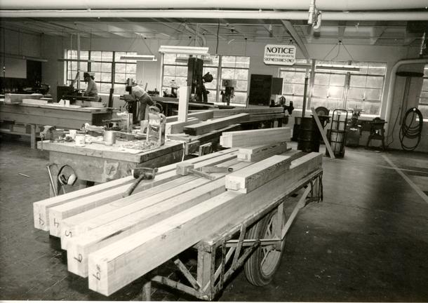 Figure 326
Colonial Williamsburg millwork shop, Numbered door jambs are in the foreground. (CWF 85-TMC-1125, 13s)
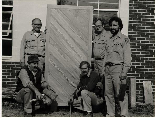 Figure 327
Colonial Williamsburg millwork shop crew. Left-to-right rear, Roy Belvin, foreman; Dan Poucher; Tim Edwards. Left-to-right front, Lester Shanks, Larry Heath. (CWF 85-TCM-42-24A)
CHAPTER XXXIV
NAILING PATTERNS
The placement pattern for the hand-wrought T-head finishing nails used in the passage and eighteenth-century cell came from a variety of sources (Fig. 328). Some members of the window casing and trim were glued up without any nails in order to represent solid pieces. Patterns for those pieces of the window trim that did require nails were extrapolated from the exterior nailing pattern research and from Agricultural Buildings Project research. Baseboards in both the passage and the cell were fastened from a nail pattern example documented in the kitchen/domestic room at Blandfield. The batten door nail and clinching pattern was developed from a number of examples documented in the A. B. P., such as the Green Hill kitchen, the Cherry Walk dairy, the Hillsborough smokehouse, the Pruden smokehouse and kitchen, and the Coke-Garret privy.
For the nineteenth-century apartment, nail patterns for the window and door trim came from the contemporary Tabb Street Presbyterian Church in Petersburg. Cut 8d "box" nails were ordered from Tremont for use in this room.
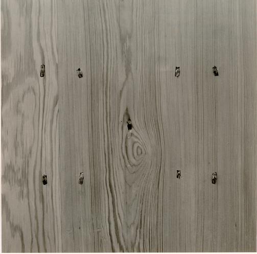 Figure 328
Detail of T-head nails on face of batten doors. (CWF 84-FD-2352-1-12s, 8)
CHAPTER XXXV
HARDWARE
Overwhelmingly, the majority of hardware produced by the Deane Forge for this project had an interior function. This included locks, latches, grates, bolts, hinges, nails and chains. This myriad of iron elements, like many other parts of the building, underwent an evolution in design that began with standard, much used CW hardware prototypes drawn in the 1940s and ended with fresh, newly recorded examples. Extant, in situ examples of eighteenth-century hardware, recorded as part of the Agricultural Buildings Project, indicated a variety of contemporary detail not only between different structures but also within the same structure. The grates, discussed earlier, were not subject to this rule except in the sense of a handcrafted variety. The design and manufacturing history of the grates suggested a consistent form. On the other hand, locks and hinges are many times found to vary and it was with these items in particular that a conscious effort resulted in different prototypes.
The archaeological evidence from the hospital's foundations contained both good and bad news. On the positive side, there were quite a few artifacts in a well-preserved state. The bad news: they were primarily late nineteenth century. There were, however, some earlier artifacts such as a hasp like 340 those commonly used with padlocks and one HL hinge. The one padlock from the site was clearly associated with the pre-hospital Jones house. Among the most significant nineteenth-century artifacts were a number of iron bedsteads and some cast iron sash. The former was reproduced for the nineteenth-century "apartment;" the sash, because of its exterior placement, could not be represented in the reconstruction. Many more artifacts were found useful in the medical interpretation of the hospital.1
Hardware in the study collection of CW's Office of Excavation and Conservation was also consulted. Unfortunately, this collection was not useful for prototypes due to the unstratified and generally unidentified nature of the artifacts.2
HL Hinges
Lacking other documentation, there was no reason to think that the hospital's exterior panelled doors were hung on anything but conventional HL hinges. The first specific prototypes for these hinges were the Greenhill Kitchen in Campbell County and southeast dependency at Mt. Airy. When it was discovered that one of the few architectural hardware artifacts from the hospital, a 12" HL hinge, matched the two previously chosen prototypes, the excavated hinge became the prototype from which drawings were made.
The passage-to-lobby door in the reconstructed wing also received a pair of HL hinges. In this case, however, a special hinge was made at the Deane Forge. In order to keep the 341 passage door closed, and to avoid the visual intrusion of modern hardware, a "rising joint" hinge was made. This type of hinge had been used in the Historic Area, but had been machine manufactured and its thick barrel did not resemble an eighteenth-century hinge.3 Atop hinge was made and, having been tested with success at the millwork shop, was used for the double thick passage door.4
Bivalve Door Bolts
To secure the inactive leaf of the north bivalve door, two surface mounted bolts were designed for the top and the bottom of the door. A bolt from the cellar door of the Alexander Craig House was the initial prototype. Examples were then recorded at Berkeley and at Shirley and found in the CW warehouse collection of antique hardware.5 The bolts at Shirley were particularly interesting because they represented a variety of detail and form combined in a hierarchical arrangement in one room. Very simply, the door bolts at the bottom of the door were very plain while those at the top, at eye level, included brass fittings and were more decorative. The bottom bolt that was very similar to the Craig House example was chosen as a prototype (Fig. 329, 330).
Use of the front doors called attention to two problems. First, the doors would not stay open flat against the walls. Second, the top bolt on the inactive leaf could not be reached by everyone. The first problem was simply solved by
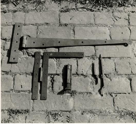 Figure 329
Examples of the hardware made at the Deane Forge, including a cross-garent hinge, an H-L hinge, a door bolt (later replaced by a different prototype) and spikes used to secure the lightning conductor to the wall. (CWF 84-DS-2238-7s)
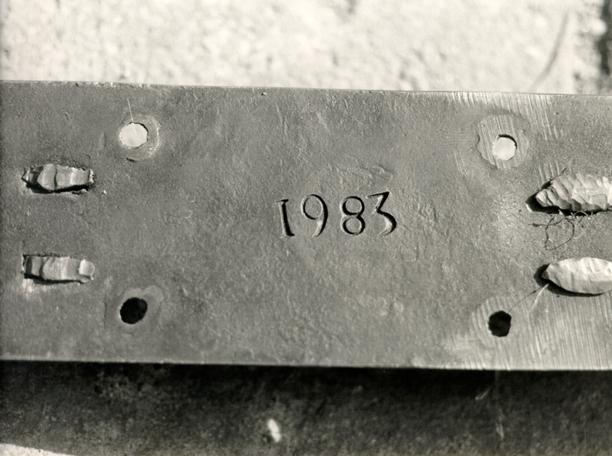 Figure 330
Detail of the underside of a door bolt. (CWF 84-DS-2239-18s)
342
installing small wrought iron hooks and eyes to the walls and doors respectively.6 The second problem required a more thoughtful approach and proper prototypes. Because of its historical association with the smaller bolt, the long bolt from the top of the Shirley door was first considered as more appropriate than a simpler mid-nineteenth century example from the Tabb Street Presbyterian Church in Petersburg.7 This decision was overturned, however, in favor of an eighteenth-century example, much like the Petersburg bolt, from the cellar door at Tuckahoe.8 The top short bolt on the inactive leaf, which had been replaced by the longer bolt, was then placed on the bottom of the active leaf as an added measure of security.
Rimlocks
With the number of doors, locks, and miscellaneous hardware one can imagine at the hospital, it is no wonder that blacksmith James Anderson's account book indicated that he made frequent trips to the building-for repairs. Anderson's ledger entries for the year 1789-1790 document this remarkable frequency of repair: in that year Anderson worked at the hospital or on hospital work nine out of twelve months; some months included up to six separate visits.9
Anderson's hospital account notes what he was repairing and the price, but it does not refer to the location within the building. In addition, these references are rather vague, e.g. "locks" and "keys" do not inform one as to the type of lock. To 343 clarify the Anderson work, an analysis was made of similar contemporary references in Anderson's ledger that refer to domestic hardware repairs in and around Williamsburg.10 The hospital accounts refer to "door lock," "door lock key," "lock," and "key." Based on the consistent use of the same terms for domestic repairs, and on Anderson's use of the descriptive terms "pad locks," "stable locks," "stock locks," "screw'd lock" and "brass locks," the hospital "door locks" were most likely iron rimlocks rather than padlocks. The repair price comparison is also useful. The price for mending hospital "door lock keys" is higher than Anderson's work on "pad lock keys," just as prices for repairing "door locks" and "locks" are higher than "pad locks." The same holds true for "door lock springs." The conclusion one can draw from all of this is that a goodly number of iron rimlocks were in use at the hospital. Assuming that there were only a small number of exterior door and principal interior door rimlocks in the building, the cell doors could account for the high number of locks and repairs. There is also an order in 1800 for 18 imported "iron rim locks" for the hospital.11 Even though these were not used after their arrival, they might have been intended as replacements for the locks that frequently needed repairs.
The type of lock had been chosen for the exterior, passage and cell doors, but further classification was necessary. Distinguishing the relative spaces through lock details was the next step. Locks with knobs, being highest in the 344 classification, would be placed on the most publicly important door, the north door. Analogous secondary doors, such as the rear door at Marmion and the hyphen door of the southeast dependency at Mt. Airy, suggested that the hospital's east and west doors and the inner passage doors would have rimlocks without knobs in combination with a thumb latch.12 The cell doors, on the lowest end of the scale, would receive rimlocks with knobs or latches. The cell doors were further distinguished by additional hardware to be discussed later. The Brush-Everard front door, with a knobless lock and latch, argues against any assertion that similar hardware on the east and west doors was too modest in scale.13
Rimlocks for the cell doors, 7 ½" x 11 ½", were based on the rimlock excavated from the Williamsburg Gaol's privy and on sizes from analogous locks such as the Prince Edward County Debtor's Prison and the Berwick-on-Tweed Jail door locks. The inner working mechanisms for these were based on examples in the CW antique hardware collection. The north door rimlock 7 ½" x 4 3/8", was based on Lock No. 221 from this collection and on a similar lock at the Ridout House (exterior door to stair passage) in Annapolis. Locks for the east and west doors and the inner passage door were based on the same prototypes as above in addition to an example at Mt. Airy (door from hyphen to stair passage in southeast dependency).
The thumb latch prototype for the east passage door was one from the Hammond-Harwood House in Annapolis, where it was 345 found in situ on a second floor stair hall door.14 For variety, the west passage/east exterior door received -a thumb latch based on an excavated example from the Prentis House site. Although this artifact was from an unstratified excavation, it is similar to one excavated from a circa 1780 context in the Custis well.
Cell Door Bolts
Written and illustrative sources led the committee to believe that a single means of securing the cell doors was, historically, inadequate.15 Eighteenth-century jails, prisons and hospitals for the insane commonly employed "an extravagance of locks, of bolts, of iron bars to shut the doors of the cells…"16 In addition to rimlocks or stocklocks, the most common means of securing heavy cell doors was a hasp and padlock system. Eighteenth-century Virginia county jail records with references to padlocks certainly indicate some sort of hasp arrangement.17 Hasps and padlocks can be used together in three ways: a) in the most conventional manner, with a moveable hasp hanging from a staple and that is placed over another staple and secured by a padlock; b) a strap-like stationary hasp mounted on a door that fits over a staple when the door is in a closed position; and c) a hasp, as an extension of a bolt mounted on a door, that fits over a staple when the bolt is thrown to its locked position.
Type C was clearly the correct model for the hospital. Examples of this type of bolt are documented at St. Luke's Hospital in London (Eighteenth century) (Fig. 331);18 the
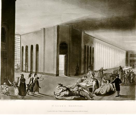 Figure 331
Drawing of St. Luke's Hospital, 1809, London, by Rowlandson and Pugin. (CWF C77-18, G1967-296)
346
Pennsylvania Hospital's cellar cells;19 the gaol in Warwick, England (early eighteenth century);20 the Town Hall Gaol, Berwick-upon-Tweed, England (eighteenth century);21 Newgate Prison, London (eighteenth century);22 and a variation at the Eastville Jail, Northampton, County, Virginia (early nineteenth century).23 In all of the examples there are two bolt-hasps on each door, one at the top and one at the-bottom. A rimlock is commonly found between them. A similar bolt-hasp was used for an eighteenth-century cellar window grate at the First Bank of the United States (1795) in Philadelphia (Fig. 332).24 Locally, the Williamsburg Gaol, whose cell door hardware might date to the eighteenth century, features a type B hasp without a bolt.25 Finally, and most importantly, when additions were made to the Public Hospital's 1821 and 1824 advance buildings in 1833, the cell doors were to be secured by "a lock and hasp as the doors of the old houses have on them."26
One bolt-hasp was approved for each of the hospital cell doors (Fig. 333). As a design prototype, the Dean Forge blacksmiths relied on the bolt from the First Bank of the United States for the basic shape. The length was calculated from photographs of the Warwick and Berwick-Upon-Tweed examples. The keepers were modeled on the same examples. The bolt and rimlock placement on the door was just below and just above the middle batten respectively, based on the Berwick-Upon-Tweed example Fig. 312).
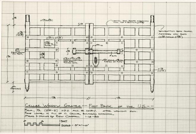 Figure 332
Cellar Window Grates from the First Bank of the U.S., ca. 1795-1797. Sliding bolt and hasp become the principal prototype for the Hospital cell doors. Drawing by Edward A. Chappell. (CWF 86-369)
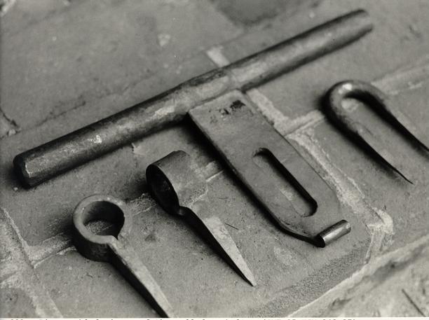 Figure 333
Disassembled pieces of the cell door bolt. (CWF 85-TCM-342-37)
Padlocks
Padlocks were needed for the cell door bolts, for the window grate in the eighteenth-century cell, for the bulkhead hasp and for the two fence gate hasps.
There were two sources for Public Hospital padlock designs. In response to a 1980 visitor's letter calling attention to inappropriate padlocks in the Historic Area, Edward Chappell documented a number of examples from the artifact collection of the Virginia Research Center for Archaeology.27 Indeed, it was determined that the warehouse-distributed padlocks found around the Historic Area are composed of a handwrought case, modelled on a nineteenth-century example, in which the production blacksmiths have placed the workings from twentieth century "railroad padlocks." The "ears" on top of these locks and the attached chain make them inappropriate.
To this previously recorded information was added measured drawings of the large padlock excavated from the Williamsburg Public Gaol site, and several padlocks excavated from the James Anderson site (Fig. 334).28 As prototypes for the Deane Forge blacksmiths, the following examples were chosen: four of the Bray site (Kingsmill) examples (VRCA, ca. 1770) for cell doors; two of the Kingsmill Tenement examples (VRCA, post 1770) for cell doors; two of the Anderson/Wills Cove, Suffolk, Virginia, examples (VRCA post 1755), one for the window grate and one for the bulkhead; one Williamsburg Gaol example (unstratified but similar to a ca. 1770-80 example in Artifacts of Colonial
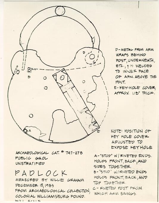 Figure 334
Public Gaol padlock used as one prototype for the Public Hospital. Drawing by Willie Graham.
348
America) (CWF) for a fence gate; and one example from the Littletown Quarter (Kingsmill) VRCA, ca. 1750-1770 for the other fence gate.
Due to a delay in the hardware delivery schedule, warehouse padlocks were used temporarily for the cell door bolts and the fence gates.29
Strap Hinges
Strap hinges were used for the cell doors and exercise yard fence gates. Traditionally, strap hinges are found on doors of substantial construction and secondary structures such as work or storage buildings. Eighteenth-century jail doors are commonly hung on strap hinges, such as at the Warwick, Berwick-Upon-Tweed, and Newgate examples discussed earlier. County jails in Virginia were unusual if they did not have ". . . a Good Sufficient Doore well hung with hooke & hinges… ."30 Not surprisingly, hinges are not mentioned in Robert Smith's or Benjamin Powell's specifications. The one eighteenth-century clue, although not by any means conclusive, is James Anderson's account for hospital work in March, 1791: "To mending a pair of large hinges for a door."31 For heavy double-sheathed or batten doors, the strap hinge was functionally the best hinge for the job. The 1833 specifications for additions to the 1821 and 1824 hospital buildings call for the cell doors "…to be hung by strong hook and eye hinges… ."32 Pennsylvania Hospital records from 1792 refer to a new door frame "drest & fix with eye Bolts for 349 Lunatics," no doubt a reference to strap hinges.33 Western State Hospital's original 1828 building also features cell doors hung on strap hinges.
Strap hinge prototypes for the cell doors began with standard CW hardware file drawings (type 1, west gate Coleman House) and ended up as a combination of the Archibald Blair smokehouse hinge (for the size, 2' 6") and the strap hinge from the excavated hospital foundations (for details) (Fig. 335). To add some variety to such a large amount of hardware, two of the cell doors received strap hinges from two different prototypes.34 The south central door hinges, slightly smaller than the others, are derived from the Howard's Neck carriage house. The eighteenth-century cell door has a cruder, shorter hinge from the Howard's Neck stable (Fig. 336).
Prototypes for the strap hinges on exercise yard fence gate also changed. These tall, heavy gates required exceptionally large hinges. The hinges were first designed to be a combination of the size of the Mt. Airy stable door hinges and details from the Archibald Blair smokehouse hinges. This later changed when an appropriate size hinge was found at the Lancaster Jail, Lancaster County, that could be made without alteration. The most relevant reference to fence hardware is one in 1815: "To Hanging the mens Yard door puting on two Iron Straps."35
All of the cell door hinges were fastened with wrought rose-head nails. Leather scraps from the saddlemaker's shop were
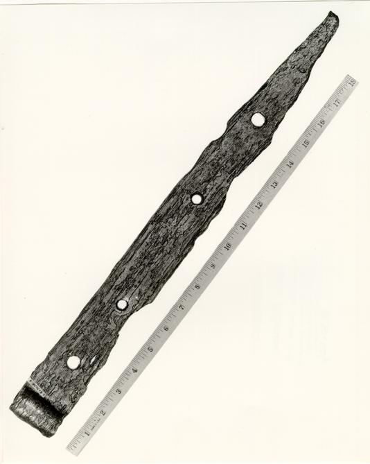 Figure 335
Strap hinge excavated from the Public Hospital. (CWF 83-FD-426)
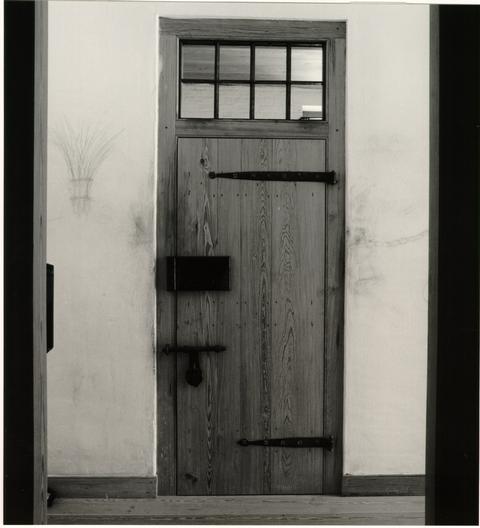 Figure 336
Cell door of the reconstructed eighteenth-century cell showing different strap hinges. (CWF 86-FD-5730, 11s)
350
used as washers. In imitation of original nail/washer examples, some nails did not receive washers.
A different manner for securing hinges without injury to the nail head seems to have been used at the hospital, though not necessarily with strap hinges. In his account for repairs in 1789 and 1790, James Anderson listed "Stays for Windows" and "Knees for Windows." In the base of the "stays," "dogg nails" are associated in the ratio of 4-5 nails per stay. A survey of Anderson's ledger finds many other references to dogg nails but all in association with hinges. A "Dog Nail," as defined in Richard Neve's The City and Country Purchaser and Builder's Dictionary, 1726, is as follows: "These are proper for fastening of Hinges to Doors, for (if made right) they will hold the hinge close without the Heads flying off, or without the help of botching, by putting Leather between the Head and the Hinge." Joseph Gwilt's 1867 Encyclopedia of Architecture defines a "Dog" or "jobent" nail as one used for fastening the hinges of doors, etc. An illustration of a dog nail from an 1812 British nail catalog shows a nail with a conical head, which presumably flattens out, thus cushioning the blow, when driven against metal.36 These unusual nails seemed to be fairly common if Anderson's ledger is any indication. Their reproduction and use were considered, but the blacksmiths had no idea of how to manufacture them.
Anderson's supply of "stays" and "knees" remains a mystery. The logical function of a "stay," in association with a 351 window, is to hold open an unweighted lower sash, like the more specific reference in 1817 to "20 ketches to hold up sash."37 One wonders why so many nails would be needed for a stay; Anderson's involvement implies that they were made of iron. The use of "knees" is just as perplexing. Other Anderson ledger references to "knees" are not in the context of windows, but that of porches, houses and stairs. The timber terminology definition does not seem to apply, especially considering that Anderson is a blacksmith and not a carpenter. One possible explanation for this term is found in the same 1812 British nail catalog, which shows a long spike-like nail called a "knee." There is no indication, however, of just how a knee nail would have been employed.
Cross-Garnet Hinges
Cross-garnet hinges are the third type of hinge used at the Public Hospital (Fig. 329). The design prototype changed in this case from a standard CW hardware drawing (Moody House smokehouse) to the Hillsborough smokehouse in King and Queen County and the southeast dependency at Mt. Airy.
Hasps
Conventional hasps and staples were needed for the bulkhead and for the exercise yard fence gates. The first specific prototype for the bulkhead hasp was derived from the Rochester House, Westmoreland County. After examining a similar 352 hasp excavated from the hospital foundations (ER 1721-A-4C) the prototype changed. The hospital hasp was severely twisted and was drawn in a restored condition.
A larger 8" hasp from the Cherry Walk smokehouse was used as the fence gate prototype.
Chains
Restraining chains in the eighteenth-century cell were made by the Deane Forge blacksmiths (Fig. 337). Chains were commonplace in facilities for the mentally ill. Historical records and contemporary illustrations bear this out. It is again James Anderson's ledger that specifically confirms this practice at the hospital. In many cases wrist or ankle chains were secured by a rivet, which required the services of a blacksmith. Examples from both the Pennsylvania Hospital's collection and from the Berwick-Upon-Tweed photograph corroborated the excavated chain found at the Public Gaol in Williamsburg.
Nineteenth-Century Hardware
By the mid-nineteenth century, most hardware was mass produced using industrial methods rather than being handwrought. With the exclusion of the cast iron sash and any outer door hardware, only two items were needed for the nineteenth-century apartment: butt hinges for the door and a wire mesh screen for the transom (Fig. 319, 338). Both of these had been recorded at
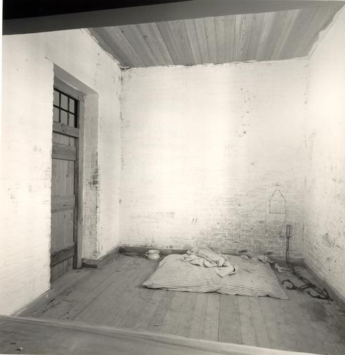 Figure 337
Eighteenth-century cell showing "zoned" grime, "bed" and blanket, chamber pot, and restraining leg chains. (CWF 85-FD-33-1)
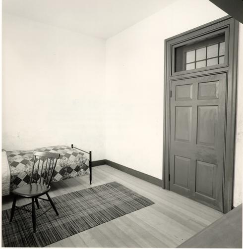 Figure 338
View of nineteenth-century "apartment" with its contrastingly higher level of finish. (CWF 85-Fd-312-12)
353
Western State Hospital in the same room which provided the architectural trim details. The butt hinge was found in a McMaster-Carr hardware catalog. Screw holes were drilled in the hinge plates to match the prototype. A wire mesh screen for the transom, with close 1/4" spaces, was serendipitously discovered in the abandoned Appomattox Iron Works building in Petersburg.38 This scrap piece of screen matched perfectly that recorded in the pegged transoms at Western State (Fig. 322), and it was kindly donated by the Historic Petersburg Foundation.
CHAPTER XXXV
NOTES
"To Lawrence Smith for two padlocks for the prison door"
1722 King George Co. Prison
"To Charles Seal for 2 padlocks for the prison"
1737 Spotsylvania Co. Prison
"… the outward door was bad and wanted one padlock….
1778 Norfolk Co. Prison
". . . the inside Doors to be inclosed by the outside Doors and two large hasps & Staples to be the Outside Door and a good lock… ."
CHAPTER XXXVI
CONSTRUCTION
Reconstruction of the hospital's interior east wing was quite different from that of the exterior parts of the project. In many ways, this was model workmanship and craftsmanship. Quite simply, the reason for this is the fact that the interior is the only major part of the building constructed by a Colonial Williamsburg staff. Beginning with the research, through the specifications, drawings, material preparation and construction, there was brought to bear experience and control. Most importantly, the greatest difference was the commitment to quality and the pride on the part of the workmen in doing things correctly.1 This had happened on some other parts of the building, most notably the brickwork, but not without much effort and constant encouragement. From a supervisory standpoint, this part of the project went the smoothest. There were, however, inevitable problems encountered even here, although most of them were related to the interface with the modern structure. Specifications were finalized in the spring of 1984. Prior to this, many of the mechanical systems in this area were found to be either unnecessary or intrusive, both by design and by error. The passage, for example, had been scheduled by Roche Dinkeloo Associates and the contractor to receive air return and supply diffusers, downlights, speakers, surface-mounted smoke 359 detectors, and sprinklers (Fig. 339). Most of these essential elements were placed in the exhibit room and the viewing room. This was done with the air supply diffusers, and the transom grates serving as return air louvers (Fig. 340 - 342). Likewise, the smoke detectors were also placed in those rooms with an ADT Aero Tube heat detection wire running through the cells and passage concealed at the juncture of wall and ceiling.2 Sprinkler heads were eliminated in the passage. In the two cells, the heads are recessed in brick or plaster above the viewing room wall. Despite all these good design intentions, the contractor ran sprinkler pipes through both cells below the ceiling level and installed vertical duct work beyond the face of the intended brick wall of the eighteenth-century cell. Both of these problems were corrected.
A more serious problem concerned a steel beam in the eighteenth-century cell. This was another case of the structural work taking place far in advance of the interior reconstruction. The beam's bottom flange, it turned out, projected beyond the intended interior brick veneer wall. This problem was solved by turning the 4" brick veneer north wall into a full 9" load bearing wall (Fig. 343). The east-west beam was cut out so that the wall supports the weight of the floor above, as it would have traditionally (Fig. 344).
Construction of the interior took about four months, ending at the start of the new year, 1985 (Fig. 345). Job meetings were held every morning to discuss progress and address
360
any of the constant problems.3 Much of this work evolved without deviating from the reconstruction plan; some of the problems were insignificant and demanded little discussion, while a few of the problems required quick research to determine a related historical solution when one was necessary. In the latter category, there are a few worth mentioning. The shrinking eighteenth-century cell perfectly illustrated how a chain of events takes place. In plan, this cell was designed to historical dimensions as determined by archaeology. Its north wall had already presented a problem with the steel beam and, before that, the floor slab above had altered plans for an exposed joist ceiling. The east-west dimension was the latest in the series of problems. Despite the reconfiguration of the vertical air ducts to the west of this cell, they still protruded into the cell, causing the brick wall to, in turn, move slightly to the east. On the other side, the viewing room studs had been mis-set, pushing the east cell wall a little to the west. The total difference was only a few inches, but this affected the nailing pattern of the floor and ceiling. The floor presented no problem. The concrete slab had been too uneven for sleepers, that had been replaced by plywood, onto which the shimmed floor boards could be nailed. On the other hand, the ceiling boards had been designed to nail onto sleepers that had, in turn, been nailed to the protruding bottom part of the concrete slab's metal tray. Unfortunately, the change in dimensions had offset this pattern to the tray's undulating voids. The obvious solution
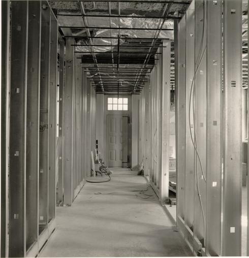 Figure 339
view of the east passage before the installation of lath and plaster. (CWF 84-FD-2293-5s)
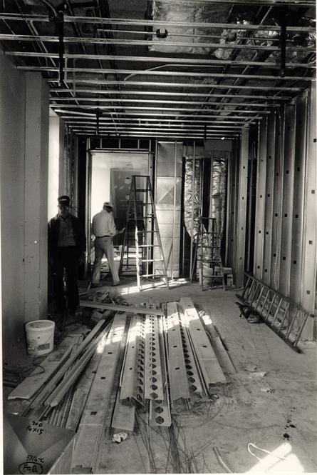 Figure 340
View of the exhibit room prior to sheetrock. (CWF 85-TCM-340-5)
 Figure 341
View looking east in the exhibit room. (CWF 84-FD-2293-1s)
 Figure 342
The exhibit room facing west. (CWF 84-FD-2618-4)
 Figure 343
Construction of the eighteenth-century cell's brick veneer as seen from the passage. (CWF 84-TCM-2351-5)
 Figure 344
Carpenters prepare the lintel for the eighteenth-century cell. The ceiling supports were necessary after the removal of a steel beam and before the north load-bearing brick wall was built. (CWF 84-FD-2293-10s)
 Figure 345
The heart pine floor is laid in the passage. (CWF 84-TCM-2659-33A)
361
here, as with the floor slab, was to first nail plywood to the ceiling, thus providing an overall common nailing surface. The erratic nailing pattern, representing unevenly-spaced joists, was found to be fairly common, such as the first floor joists at Berkeley where they vary as much as 2".
Two less complicated situations can be cited. Because of the awkward space created by the doorway in the southwest corner of the eighteenth-century cell, the head joints of the English bond brickwork became inconsistently wide (Fig. 346). Before pulling this out, several analogous situations were discovered in the southeast dependency at Mt. Airy and in the cellar at Blandfield. In those cases, as in ours, a naturally occurring problem in a lower scale space had led to a common solution: sloppy work. Recognized as a beneficial bit of realism, the wide head joints were retained.
In another situation, a steel beam in the passage space and the need for mechanical space led to a ,slightly reduced finished ceiling level, about 10' 6". This affected the two part door trim that wrapped around the transom window. The ceiling, in effect, had encroached upon the backband. Alternatives included moving the backband or stopping the plaster in front of the trim to create a slightly recessed well in which the backband could sit. The final solution called for no top backband and having the plaster come directly onto the fillet. This and the other forced quirks of building, like the idiosyncrasies of brickbond, were considered authentic telltales that exist within
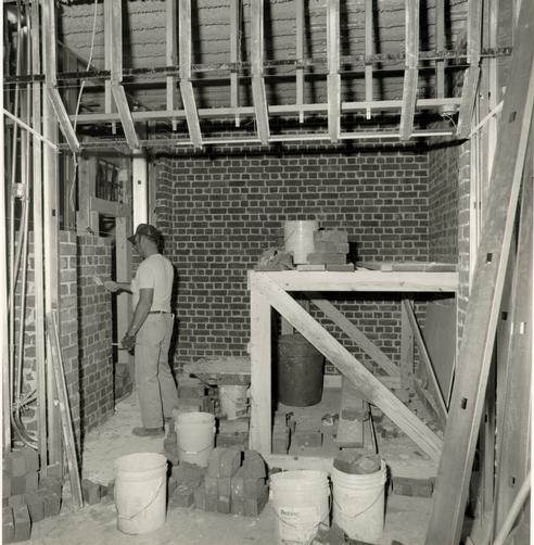 Figure 346
Bricklayer Jim Shipley constructs the eighteenth-century cell walls. (CWF 84-FD-2351, 3-10s)
362
the nature of traditional craftsmanship. They cannot be predicted or designed, they just happen.
With all woodwork in place, the plasterers began their work (Fig. 347). Time constraints demanded that this trade be subcontracted to a trusted local firm, Paul's. The use of real plaster in the passage, where visitors came in contact with the walls, was a great concern. Concessions were made for metal lath in the passage and for "blueboard" in the nineteenth-century "apartment." Reproducing the appearance of plaster on uneven brickwork or split wood lath required artificially created undulations as the ¾" brown coat was applied (Fig. 348). Corners executed freehand and consciously crafted "Cat faces" (rough textural spots) were important in the final ¼" white coat, especially in those areas on which light reflected (Fig. 349). The fine line in this work was to avoid overly exaggerated imperfection. The nineteenth-century "apartment" received a ¼" of white coat but, unlike the passage, it did not receive a whitewash finish.
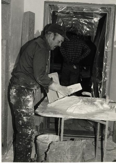 Figure 347
A plasterer prepares a batch of plaster to apply to the passage walls and ceiling. (CWF 84-TCM-2615-5)
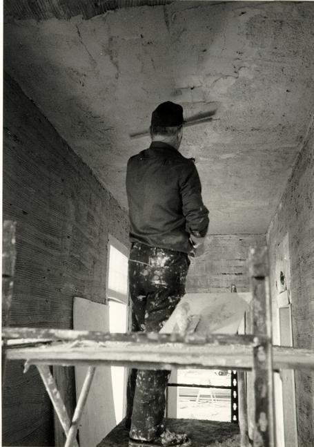 Figure 348
The first "brown coat" of plaster is applied to wire lath with waves and bumps to imitate eighteenth century plaster. (CWF 84-TCM-2614-10A)
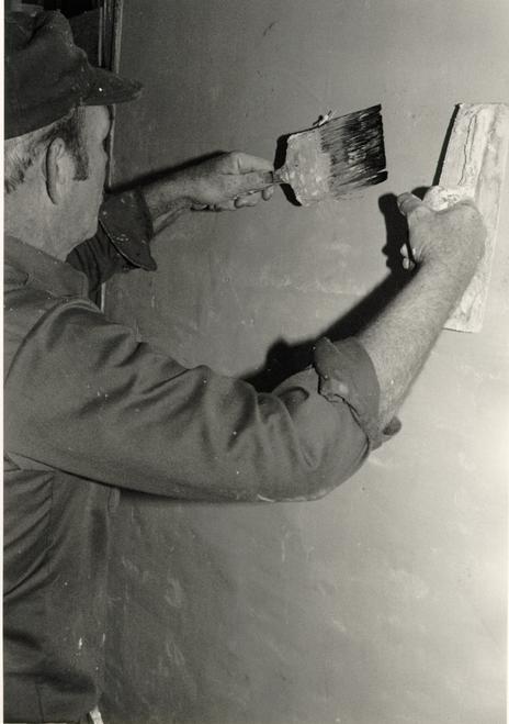 Figure 349
"Cat faces" and undulations are carefully applied to the final white coat of plaster. (CWF 84-TCM-2615-3)
CHAPTER XXXVI
NOTES
CHAPTER XXXVII
GRIME AND GRAFFITI
As a final touch, the cells and passage were given a "lived in" appearance. In a matter of hours, the newly finished rooms took on a more realistic aura. The eighteenth-century cell was given a more filthy, less maintained look than the nineteenth-century "apartment." The intention was not to convey an artificially aged space but rather to show the private environment of a patient, which by many historical accounts was rather disgusting. In keeping with the interpretive design of the cell, inferring the semi-permanent restraint of a patient by chains, a patient's zone of access was created (Figs. 350 - 351). If chained in the northwest corner, a patient spent most of his time within the range of that chain. Dirt, graffitti and broken glass correspond to this zone of intense activity in the first period cell. In contrast, the 1845 apartment represents more maintenance, and also, to some degree, a more refined form of graffitti. There is also indication through graffitti that the room has been used by a succession of patients.
The recreation of mental hospital graffitti, suggested by Shomer Zwelling, was a logical step from the decision to dirty-up the new interior surfaces. It seemed logical because virtually all historical prints of hospital interiors show graffitti. In addition, some forms of patient graffitti are in
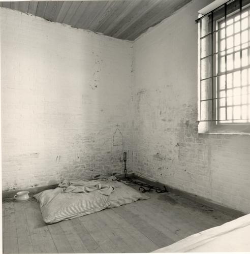 Figure 350
Eighteenth-century cell showing "zone" of filth. (CWF 85-FD-33-6)
 Figure 351
Eighteenth-century cell and the "zone" of filth at the window edge. (CWF 85-FD-33-11)
365
evidence at nineteenth-century asylums where the buildings have not been reused, such as Western State Hospital and St. Elizabeth's Hospital.
In many ways, the eighteenth-century graffitti was the easiest to reproduce. Three separate prints of Bethlehem Hospital offered a variety of images from which to choose: Hogarth's "The Rakes's Progress," 1735 edition; an engraving by Bernard Lens and John Sturt for Jonathan Swift's A Tale of a Tub, 1710; and a circa 1745 scene from D. H. Tuke's Chapters in the History of the Insane, 1882. The eighteenth-century cell received a face from the 1745 print (Fig. 352); a church from the newel post in Hogarth's print (Fig. 353); two ships based on one in the Hogarth print ,but actually drawn from examples recorded at the Whaley granary in Berlin, Worcester County, Maryland and the Homestead Farm tobacco barn in Calvert County, Maryland (Fig. 354); and a set of initials, IH, based again on the Hogarth print, but using the actual initials of an early patient, Isaac Howlett of Gloucester County, who was admitted in March 1787.1
Unfortunately, figurative nineteenth-century hospital graffitti could not be found.2 What we do have are patients' drawings and writing on paper. Five different forms of this were chosen for the nineteenth-century "apartment" from Eastern State Hospital records: a triple spiral drawing by Capt. James De Cocy dated 1853, reproduced on the north wall in pencil (Fig. 355); a phrase "the gates of hell," taken from the same document and scratched on the door by a nail (Fig. 319); a statement from a
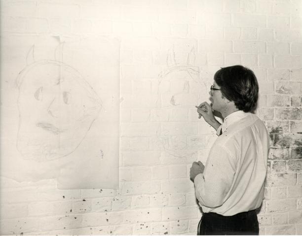 Figure 352
Travis McDonald reproduces a face taken from Jonathan Swift's A Tale of a Tub. (CWF 85-CC-31-16)
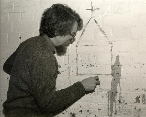 Figure 353
Edward A. Chappell reproduces a church by means of a nail. (CWF 85-CC-31-2)
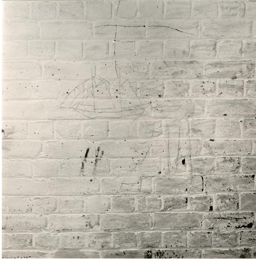 Figure 354
Reproduction of a ship taken from a drawing at the Homestead farm tobacco barn. (CWF 85-FD-312-6)
 Figure 355
Reproduction of a spiral drawing from Capt. James DeCory and a statement by R. Floyd Miller. (CWF 85-FD-320-11)
366
patient, R. Floyd Miller, written in the directors' minutes book in 1845 and reproduced in pencil on the north wall (Fig 355); a drawing of two doves by De Cocy with the words "The Father of White Indians," reproduced on a sheet of paper and attached to the east wall above the bed; and an "Epistle" also by De Cocy reproduced in pencil on the north wall.3
In the passage, the use of graffitti implies that the space served the patients for more than circulation alone. This fits with Shomer Zwelling's feeling that to some extent, the patients milled about in the passages supervised only by slaves, who exerted little authority or control. Hogarth's Bethlehem print was used for the most dramatic image reproduced in the passage, a globe affixed by a chain with an associated sun and moon (Fig. 336). A sheaf of wheat or grass, taken from the Lens and Sturt engraving, was also reproduced in the passage near the west door.
The process of creating the look of patient use was largely one of imagination. Armed with mud, coffee, grease, pencils and carbon paper, members of the Design Review Committee conscientiously attacked the spaces (Fig. 356).4 The result, it is hoped, takes authenticity beyond where it has previously tread at Colonial Williamsburg.
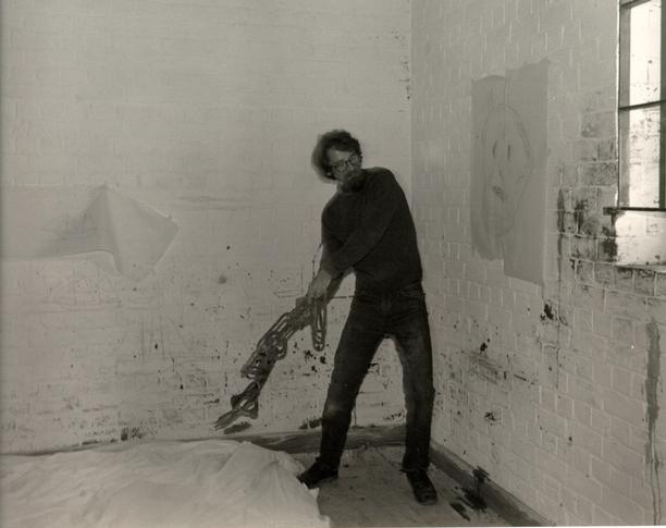 Figure 356
Edward A. Chappell preparing the wall in the eighteenth-century cell. (CWF 85-CC-31-9)
CHAPTER XXXVII
NOTES
THE PUBLIC HOSPITAL:
AN ARCHITECTURAL HISTORY AND
A CHRONICLE OF RECONSTRUCTION
Architectural Research Department
Colonial Williamsburg Foundation
Williamsburg, Virginia
1986
[PART III]
VOLUME III [4]
| Chapter | Page |
| XXXVIIIBrick | 368 |
| XXXIXMortar | 388 |
| XLShingles | 397 |
| XLIPaint | 415 |
| XLIIGlass | 420 |
| Reconstruction Chronology |
| Index to Design Review Committee Minutes |
CHAPTER XXXVIII
BRICK
As planning for the Public Hospital reconstruction progressed in the first half of 1981, it was assumed that brick for the project would come from our own craft demonstration process.1 An immediate problem was the structural quality of the CW brick.2 It was known that the most recently made brick had tested far below ASTM standards. Suggestions for improving the product were not acted upon in the spring, so a small experimental production was then planned for the later summer.3 By this time, however, the committee decided that the high number of variables inherent in the eighteenth-century process of making and firing brick meant that a short period of experimentation was unlikely. Laboratory tests on original brick, CW brick from the 1940s, and recently made CW brick indicated that a good part of the problem with the latter was caused by the particular clay that had been used; a search for a suitable local clay deposit and subsequent experimentations on the same seemed unfeasible given the late starting date. Because of the scheduling constraints associated with a general contractor, the committee decided that expediency dictated a reliance on a brick manufacturing company.4
The initial step in reproducing brick for the hospital was to examine brick from the original foundations. Six brick from the highest part of the hospital's north pavilion wall were 369 removed and cleaned.5 It was observed that, for the most part, the extant foundation wall brick were light shades of brown and red. The highest points, nearest grade, were consistently darker. This was confirmed later when in the fall of 1982 the entire north and south exterior foundation walls were exposed and cleaned for color photographs (Fig. 87 - 90). Based on the generally dark colors of contemporary local brickwork seen in the Courthouse and the Church tower, it was assumed that the lighter brick from the clamp had intentionally been placed below grade. The exception was the south pavilion's east corner which had been rebuilt at an undetermined date with a full color range of dark brick. Randomly placed glazed brick, both headers and stretchers were, in evidence throughout the foundations.
THE COMPETITION
Six bricks reflecting the range of color in the hospital foundation walls were removed. Five out of the six bricks closely matched the Courthouse and the Bruton Church tower. One brick, a bright orange, fell outside of the colors found in these above grade, contemporary walls. The five select brick were sent to Victor Cushwa & Sons of Williamsport, Maryland.6 Eventually, five producers of handmade bricks were involved in the selection process: Cushwa; Alwine of New Oxford, Pennsylvania; Old Carolina of Salisbury, North Carolina; Old Virginia of Salem, Virginia; and the Royal River Company of 370 Yarmouth, Maine. Based on initial samples submitted, the latter two companies did not receive invitations to compete.
Cushwa, Alwine and Old Carolina each sent representatives to Williamsburg to meet with the Design Review Committee and to examine the Courthouse and the Church tower. After receiving detailed color photographs of the Courthouse and Church tower brickwork, the three companies submitted field and "rubbed" brick samples (Fig. 357).7 Following constructive feedback, each of the companies paid another visit to Williamsburg and submitted additional samples, this time including glazed brick.8 Based on the next samples of 100-150 brick, which were constructed in February 1982 as small panels of field, rubbed and glazed brick, old Carolina's was chosen as the best product (Figs. 358 - 361).9 Although the other companies showed promise in rubbed and glazed brick, Old Carolina's field brick was far superior. Its superiority resulted from Old Carolina's own patented system of using pulverized coal as fuel for their tunnel kiln. Coal dust produces an uneven heat in a tunnel kiln as opposed to the even heat generated by conventional oil or gas fuel. In effect, this creates a natural variation in color on each individual brick and between bricks in the entire firing. Another crucial difference is the depth and appearance of the coloration. Coal-fired bricks generally have a surface coloration that extends well into the body. With conventional fuels, coloration is achieved through a surface coating of silica or other minerals, producing the effect of a veil or thin skin of
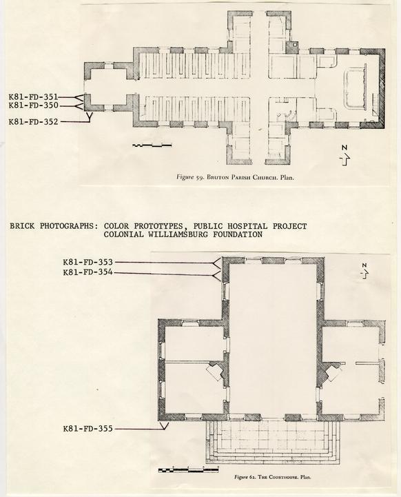 Figure 357
Areas of Bruton Parish Church and the Courthouse that were photographed in detail for brick color reproduction.
 Figure 358
The original test panels of Cushwa, Old Carolina, and Alwine brick. (CWF K82-FD-269)
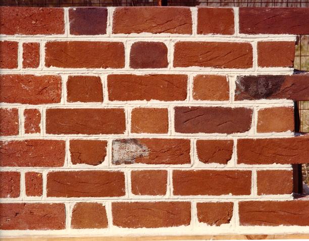 Figure 359
Cushwa brick, first competition panel. (CWF K82-FD-270)
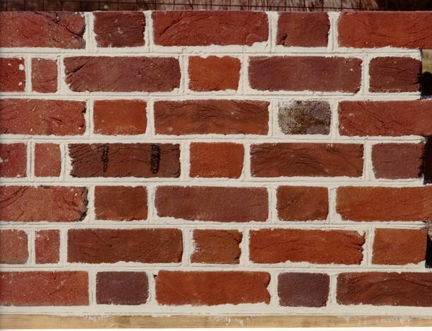 Figure 360
Alwine brick, first competition panel. (CWF K82-FD-275)
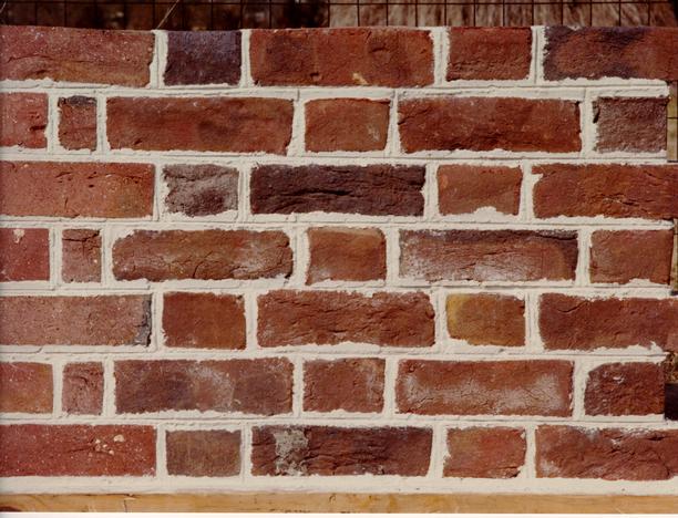 Figure 361
Old Carolina brick, first competition panel. (CWF K82-FD-271)
371
uniform color. The latter seemed particularly disturbing, assuming that the reconstruction would have a rather long life.
The next step in the review sequence was designed with a twofold purpose. Gauged work, for the arches and the belt course, constituted one of the most potentially problematic parts of the brick project. Anxious to examine Old Carolina's gauged work, the committee asked them to supply a full range of sample brick which could be constructed by CWF masons and used as the prototypical master job panel. This panel contained sections of the English bond foundation, the water table, field brick, rubbed corners, a rubbed window jamb, a windowsill, one half of a window arch, and a belt course (Figs. 362-363). To the committee's great disappointment, Old Carolina had made no improvement in the quality of their samples. In fact, the samples had regressed and the poorly cut "rubbed" and gauged work actually precluded the quality of workmanship expected for the master panel.10 This regression was due to a lack of supervision and quality control at the plant which thenceforth required regular supervision by the architectural coordinator and others.
Old Carolina's unsatisfactory performance compelled the committee to open a second and final round of competition among the same three companies. Cushwa, Alwine and Old Carolina were sent overall and detailed color photographs of the three first stage competition panels (Figs. 359 - 361); they also made another trip to Williamsburg for discussions.11 Before Cushwa and Alwine could submit new samples for a full size panel, old
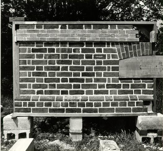 Figure 362
First large scale test panel using Old Carolina brick. (CWF 82-MR-3975)
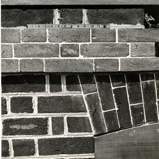 Figure 363
Detail of the first full scale Old Carolina brick panel. (CWF 82-MR-3974)
372
Carolina's new samples were constructed as a fully complemented panel by the most promising masonry subcontractor, Snow, Jr. and King (Fig. 97 - 98).12 Both the brick and bricklaying in this panel were favorably reviewed, especially the quality of the gauged arch and belt course which had been cut at Snow, Jr. and King's site in Norfolk. To be fair to other masonry subcontractors who had been invited to bid the hospital/gallery job, and to inject a reasonable assurance of top quality work, a prequalification competition was established among five firms (Fig. 364). Each firm was asked to construct a full panel as Snow, Jr. and King had done, and they would then be judged as qualified or not to bid the job with the general contractor. To expedite the selection of a brick company, two of the subcontractors were directed to use Cushwa's and Alwine's new samples for their panels (Fig. 365-367). The Design Review Committee judged each of these panels according to eighteen aspects of construction quality. Even though two subcontractors were given a second chance to demonstrate their work,13 only two out of five companies qualified.14 Based on their bid, as well as their work, Snow, Jr. and King were awarded the masonry subcontract for the hospital and gallery. It was also decided that Snow, Jr. and King, rather than the brick supplier, would cut the gauged brick.
Phase two of the brick evaluation, based on the above mentioned panels, in which thirteen separate aspects were critically reviewed, resulted in Old Carolina as the selected
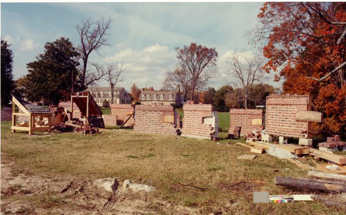 Figure 364
Brick panels constructed as part of a pre-qualification of masonry subcontractors. (CWF K82-FD-842)
 Figure 365
Alwine brick, second competition panel. (CWF K82-FD-839)
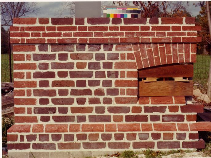 Figure 366
Cushwa brick, second competition panel. (CWF K82-FD-840)
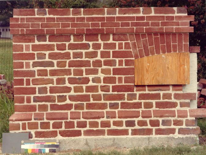 Figure 367
Old Carolina brick, second competition panel and first panel by Snow, Jr. and King. (CWF K82-FD-755)
373
supplier.15 Even at this stage, however, despite an active involvement of the architectural coordinator in their experiments, Old Carolina's product was not entirely acceptable. Finally committed to a supplier, the committee discovered that achieving the end product was a lesson in frustration and perseverance.
MANUFACTURING: FIELD BRICK
It proved helpful in the beginning to tour the old Carolina plant in Salisbury, North Carolina and learn about the company's brickmaking process. Old Carolina is an old and, in many ways, antiquated plant. Quality control and supervision became the biggest stumbling blocks given the amount of experimentation needed for the job. During the peak months of manufacturing, representatives from Architectural Research and Construction Management made weekly trips to the plant.
Old Carolina, and seemingly every other modern brick company, uses shale as their raw material. The sequence of brick making is as follows: a) a front end loader is used to mix approximately 3/4 of its bucket with rough shale and ¼ with a finer grade shale (Fig. 368); b) this mixture is dumped into a hopper where a crusher reduces the particle size (Fig 369); c) a conveyor belt takes the crushed shale to a hammermill where it is again reduced in size (Fig. 370-371); d) it then passes over a vibrating screening machine which filters out rocks and any remaining large particles (Fig. 372); e) a conveyor next takes
 Figure 368
Old Carolina Brick Company. Different grades of shale are mixed. (CWF 83-1304s-TCM)
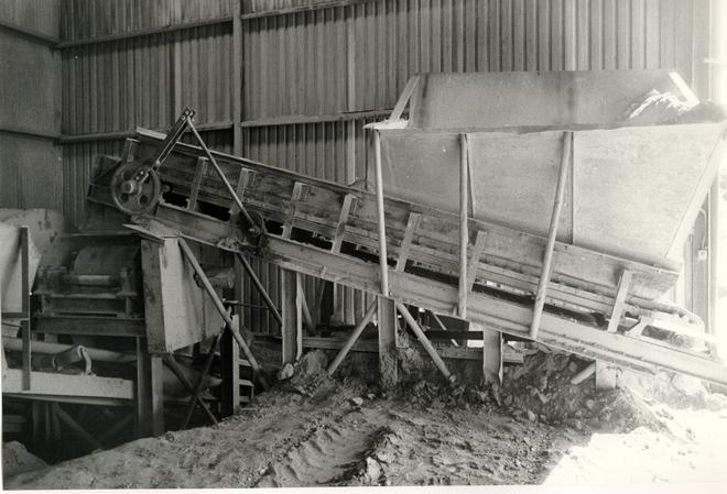 Figure 369
Old Carolina Brick Company. The hopper where rough shale is dumped and crushed. (CWF 83-1306s-TCM)
 Figure 370
Old Carolina brick Company. Conveyor belts used to transport crushed shale. (CWF 83-1307s-TCM)
 Figure 371
Old Carolina Brick Company. Hammermill used to pulverize shale. (CWF 83-1308s-TCM)
 Figure 372
Old Carolina Brick Company. Vibrating machine screens rocks and large particles from powdered clay. 9CWF 83-1309s-TCM)
374
the material to a pug mill where it is mixed with water and compressed (Fig. 373); f) extruded chunks of material (Fig. 374) pass to the "mud throwers" who roll the "clay" in sand and then throw it into eight-cell wooden molds (Fig. 375); g) after placement on trays (Fig. 376), the brick are dried for about one day in a drying kiln (Fig. 377); h) the dried brick are then stacked on a kiln car (Fig. 378) and sent through the tunnel kiln for a 2-3 day period (Fig. 379); the final step is that of blending the cooled brick by means of a monorail loader which moves around to stationary loading points so that three to five men can load the pallets from different parts of the kiln car (Figs. 380 - 381). Color variation for the different series of Old Carolina brick is achieved by adding manganese to the crusher hopper and by adding rutile and magnetite to the sand in which the wet mud is rolled. Temperature during firing also determines the color to some extent.
The Design Review Committee had determined from Bruton tower and the Courthouse that four basic colors were needed in equal amounts, with a natural range between them: dark red/plum, light red, dark brown and light brown. The earliest experiments in September 1982 involved the ingredients of manganese, magnetite and rutile. It was also found that the best plum colors were produced by flashing in the kiln. Brick is normally stacked on the stretcher face, but to benefit from the hot flashes of coal fuel they were "flat stacked" to catch the flash on their faces rather than their tops.
 Figure 373
Old Carolina Brick Company. Powdered clay is mixed in this pug mill with water. (CWF 83-1311s-TCM)
 Figure 374
Old Carolina Brick Company. A mud-like clay is extruded from the pug mill. (CWF 83-1296s-TCM)
 Figure 375
Old Carolina Brick Company. Wooden molds into which the clay is thrown by hand. A machine automatically west and sands the mold and then dumps it out. (CWF 83-1297s-TCM)
 Figure 376
Old Carolina Brick Company. Wet bricks are air=dried on racks for one or tow days. (CWF 83-1298s-TCM)
 Figure 377
Old Carolina Brick Company. The air-dried bricks are further dried in a drying kiln using hot air. (CWF 83-1299s-TCM)
 Figure 378
Old Carolina Brick Company. The dried bricks are stacked on a kiln car and sent through the tunnel kiln for 2-3 days. (CWF 83-1301s-TCM)
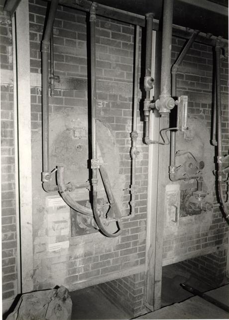 Figure 379
Old Carolina Brick Company. Burners on the sides of the tunnel regulate the amount of coal dust fuel which is blown into the kiln. (CWF 83-1302s-TCM)
 Figure 380
Old Carolina Brick Company. The monorail mixer enables the kiln car stack of fired bricks to be randomly mixed. (CWF 83-1303s-TCM)
 Figure 381
Old Carolina Brick Company. Complete cubes of mixed bricks are banded by machine for shipment. (CWF 83-1305s-TCM)
These first batches of about 120 brick each produced good results.16 The difficult colors seemed to be dark reds and light browns. Further experimentation had to wait until old Carolina received their twenty-five custom built wooden molds in April 1983. With these molds, full size production runs could be evaluated.
The first full run of field brick (5-7,000) did not have a full complement of colors due to the mechanical failure of a shot feeder which added manganese to the hopper. Batch number two, of about 24,000 brick, produced good shades of plum, dark brown and light red. To achieve darker red colors and lighter browns in batch number three (15-20,000) the temperature was varied (a lower temperature produces lighter brown), manganese was reduced (for lighter browns), red iron oxide was added (for darker reds) and the bricks were stacked with their faces closer together (so an iron reducing reaction would not be as great, hence darker red). Batches three and four produced good colors already seen, but still lacked the necessary dark red and light brown.17 By this time it was obvious that a major blending effort would be required if the sizeable number of brick already made could be used.
Batch number five, an experimental batch with no routile in the sand and fired on gas at a lower temperature, was a successful attempt at producing a dark red brick but approximately one-third of the 20,000 bricks were orange.18 Batch number six (identified as number seven) was a coal-fired 376 attempt to produce 9-10,000 additional brown colors and batch seven (identified as number eight) was flat-set in an attempt to produce more plum colors.
The final and most crucial step was the blending of the various batches of color. Snow, Jr. and King insisted that each cube of bricks arrive at the site already blended so that the bricklayers would not have to make any decisions concerning color. Blending these colors was largely subjective and a procedure better not left to chance. For this reason Travis McDonald not only supervised the blending, but also participated in the process. While the Old Carolina plant was shut down in July of 1983, 66,200 Public Hospital bricks were hand blended into 215 cubes in the space of seven and a half days. The process involved two to three men on the monorail, one man banding the cubes and David Frame, the plant owner, delivering the various cubes with a forklift to the monorail platform (Fig. 382). The monorail moves around so that each man loads part of a cube, and half of the cube is filled on each circuit (Fig. 383). All through the blending, soft orange brick were culled and discarded. Five batches provided the basic color blend. Approximately eight thousand additional bricks were blended so that they could be purchased as a surplus (Fig. 384).19
After the second round of competition determined the masonry subcontractor and the brick supplier, Snow, Jr. and King was asked to construct another full panel of Old Carolina samples in October 1982 (SJK/OC Panel #2) (Fig. 97-98). This was
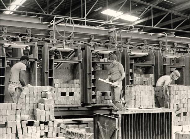 Figure 382
Old Carolina Brick Company. Travis McDonald (center) directs and participates in the color mixing of the Public Hospital bricks. (CWF 84-EAC-2072029s)
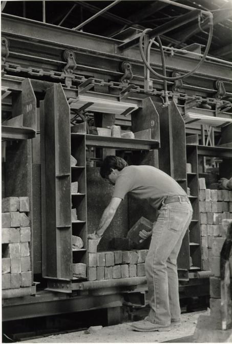 Figure 383
Old Carolina Brick Company. Travis McDonald mixes Public Hospital bricks on the monorail mixer. (CWF 84-EAC-2072s)
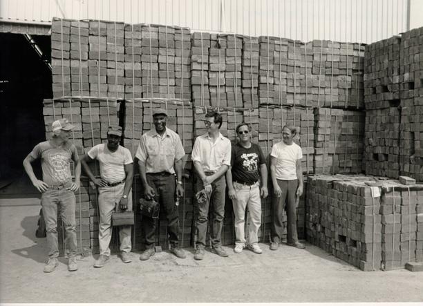 Figure 384
Old Carolina Brick Company workers who participated in the Hospital brick project. Company Vice-President David Frame is third from right. (CWF 83-TCM-5396-5s)
377
followed by yet another, final panel of Old Carolina brick (SJK/OC Panel #3) (Fig. 385). This last was the master job panel, constructed in August 1983 after the hospital foundations had been started.20
TRIM BRICK
Not surprisingly, reproducing trim brick for corners, jambs, arches and the belt course proved difficult. The initial stumbling blocks were color and texture. Included in almost all of the experiments for field brick color there were simultaneous batches of trim brick. Gas rather than coal fuel proved to be the solution in achieving both a dark red color and one that was consistent in shade. Manganese added to the shale helped achieve the right color.21 Because the trim brick was made from the same shale as the field brick, an immediate problem of texture became apparent. Shale has a large aggregate particle size which looks nothing like the fine particle size of pure clay used in eighteenth-century brick. This was a problem for the trim brick because it was to appear as if it had been rubbed. After further experimentation, a common window screen was found to filter the shale particles to a proper size (Fig. 386).
A more difficult problem arose in trying to reproduce the random yellow inclusions seen in eighteenth-century brick. These particles were never fully ground in eighteenth-century pug mills and, for some reason, they did not take on the general color of the brick body. Old Carolina's solution was to add
 Figure 385
David Frame of Old Carolina Brick Company examines a shipment of bricks. (CWF 83-1288s-TCM)
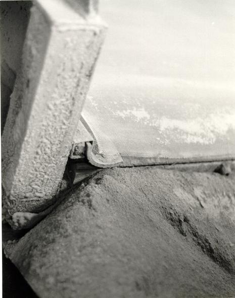 Figure 386
Detail of window screen used to screen the clay to a proper grain size at the Old Carolina Brick Company. (CWF 83-1310s-TCM)
378
lumps of fire clay into the sand in which the "clay" is rolled before being thrown in the molds. This failed to work because the sand interface between the inclusions and the body resulted in a loose bond. When a final run of trim bricks was produced, the inclusions were too shallow and thus lost during the cutting process (Fig. 387). Ultimately, the inclusions were successfully placed well into the body and were made in a supplemental batch of trim brick. Since the arches, jambs, belt course and corners had already been cut, the new supplemental pieces had to be added into the other parts at a 15-20o rate.
Because of the greater density of the trim brick other problems occurred such as an unusually long drying time and a greater rate of shrinkage. After a long series of experimental batches in which the color was too light, a successful color batch was made but the individual bricks turned out too small. Because of the difficulty in producing the proper color, the large quantity of trim brick was accepted in their small size. This was not a problem for arch pieces, the belt course, closers or jambs (where butt headers could be used), but the rubbed corners, where both faces of the brick could be seen, would have displayed the square looking headers (Fig. 388). Old Carolina was instructed to produce additional trim brick for the corners at the same time that they were producing extra trim brick with inclusions. Remaking trim brick, like glazed and water table brick, was not easy because Old Carolina had to switch from coal to gas fuel, which took several days and had to be worked around
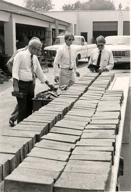 Figure 387
Members of the Design Review Committee examine the cut faces of trim brick at the Snow, Jr. and King Company in Norfolk. From left, Nicholas Pappas, Mike Snow and Travis McDonald. (CWF 83-4451s-EAC)
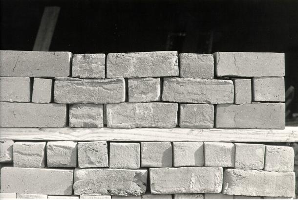 Figure 388
Square rubbed corner header faces are viewed in context with stretchers. (CWF 83-5287s-EAC)
379
their regular brickmaking scheduled. In addition, the special screening slowed the process considerably. Bricks in the next new batch of trim brick were long enough but had slumped in height to 2 ½". Finally, the third batch of additional trim brick proved successful and was shipped to Williamsburg to be cut by Snow, Jr. and King (Fig. 389). These additional trim brick were cut at the hospital site by Gary Hughes, who had cut all the other rubbed and gauged pieces at Snow, Jr. and King's plant in Norfolk (Fig. 390). The carborundum saw blade used for cutting the brick fortuitously produced no cut marks when handled by a skilled operator.
Specified sizes for rubbed trim brick were: jambs and corners 3" x 4 5/16" x 9", closers 3" x 4 5/16" x 1 15/16"; belt course: Headers 2 1/16" x 3 3/" x 3 ¾", stretchers 2 1/16" x 3 ¾" x 7 19/32", corners 2 1/16" x 3 ¾" x 6 19/3211, closers 2 1/15" x 3 ¾" x 1 13/16". Arches were cut to full scale drawings.
WATER TABLE BRICK
Molded water table and windowsill brick were specified to be lightly rubbed to remove the surface sand. Because of the relatively small number of these bricks required, only two special molds were made.
Producing an acceptable water table was not any easier than creating the other brick parts. Between June and November of 1983, Old Carolina made more than three complete water tables.
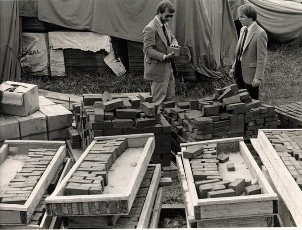 Figure 389
Travis McDonald and Willie Graham examine cut bricks at the hospital site. (CWF 84-TAC-1429s)
 Figure 390
Gary Hughes of Snow, Jr. and King cuts additional trim brick with inclusions at the hospital site. The brick was first marked by use of a template and then cut by a carborundum blade which grinds-off saw marks while it cuts. (CWF 86-EAC-5924, 22s)
380
The first run was plagued by two separate problems: the brick were too short due to an incorrect mold size and had slumped from improper stacking on the kiln cars. Batch number two bricks had a proper form and size as well as good inclusions, but were too light in color. After experimentation with various stains, refiring at a higher temperature seemed to be the answer. Because of a temporary shut-down at the Old Carolina plant (for deer season), the water table brick were taken to the Cunningham Brick Company and refired on gas at a higher temperature. Despite the fact that 10% of the brick cracked, the refiring was thought to be successful. After the brick arrived in Williamsburg, however, they were still too light when compared to the other trim brick. Old Carolina was asked to make a completely new run. This final production proved successful, but a lack of supervision led to all the headers being cut too small. With the addition of about 70 new brick, the order was complete and accepted in October 1983.
Specified sizes for the water table and windowsill brick were: headers 3" x 4 5/16" x 4 5/16"; stretchers 3" x 4 5/16" x 9"; fillet 5/8"; corner units (4 left and 4 right) 3" x 4 5/16" x 9"; closers: 3" x 4 5/16" x 1 15/16". The closers were actually cut in a range from 1 ¾" to 2".
GLAZED BRICK
Glazed brick was one of the most difficult parts of the order to achieve. The method of glazing used by Old Carolina was 381 to apply a potter's slip glaze which fully complemented the overall color range to already fired bricks. Based on a survey of glazed brick at the Bruton Church tower, the quantity had been established as eight percent glazed headers and two percent glazed stretchers, or, in actual numbers, approximately 1500 headers and 400 stretchers. These percentages were further defined as 60% fully glazed headers; 40% partially glazed headers; 100% partial glazed stretchers; 75% of a white-gray shade; 25% in a combination of light and dark colors; 50% combination glossy and matte texture; and 25% each of a glossy or matte texture. Original examples indicated wide ranges of color, texture and application. Although the slip glazes were somewhat uncontrollable as to final color and texture, the application pattern was dictated entirely by the applicator, who in most cases, was David Frame. Several trips to Williamsburg and detailed color photographs of the church and courthouse helped teach the new art of artificially creating glaze patterns which represented the effect of bricks that had been hand stacked in a clamp.
Unfortunately, there were many opportunities to perfect this art of application. For five months, between May and November 1983, five separate batches of glazed brick were made and examined. Batches of 1000-2000 bricks were individually examined and culled with an acceptance rate generally not higher than 5%. In the case of later batches, Old Carolina hedged their bet and glazed two faces of each brick, which required that the 382 accepted face be marked with crayon. Both coal and gas were used for these firings, although the former seemed to create more matte finished bricks due to blowing ash in the kiln.
Representative samples of glazes were routinely brought back to Williamsburg and compared to original examples. Because the glazed brick were made separately, they were not mixed into the blended cubes of field brick and had to be added to the walls in a percentage that approximated that at the church tower and courthouse. The difficulty at this stage was preventing the bricklayers from inserting them at regular intervals.
WALLACE GALLERY BRICK
Initially the brick for the Wallace Gallery wall was conceived as a different, yet sympathetic to that of the Public Hospital. This was to be achieved through use of the same material in a general likeness of color; the major difference was that brick for the hospital would be handmade and that for the gallery would be machine produced. The competing brick companies were presented with the carrot of supplying the 120,000 gallery brick in addition to the 60,000 hospital brick. As the project progressed, the Design Review Committee realized that the excessive length of the gallery wall, when constructed with a modern brick, might impact too harshly on the hospital. They offered Kevin Roche the option of using for the gallery a handmade brick slightly different from the hospital's. Roche agreed to this and discussions were begun with Old Carolina to 383 supply their standard oversize series 700 brick (8 ½" x 2 ¾" x 4") for the gallery. In addition to a different size, a slightly different color (the gallery brick would not be specially blended), and the absence of glazed and rubbed brick, the committee also recommended a different mortar color and mortar joint. Kevin Roche's choice of a nineteenth-century Garden Wall Bond was entirely in keeping with the committee's objectives. The philosophy underlying these recommendations is important enough to be quoted here from a memorandum:
The Public Hospital Design Review Committee believes there should be a perceptible variation between the brickwork and mortar of the Public Hospital and that of the Wallace Gallery. Our reasons for this are based on a concern for the special visual and educational qualities of the Historic Area.
A contrast is important since the Hospital is a reconstruction of a building that existed on this site in the eighteenth century and the Gallery is a modern building that never previously existed. To have matching brickwork and mortar details is to implicitly state that the two buildings are contemporary, whereas a slight variation between the brickwork of the two buildings avoids that appearance and at the same time lends some integrity to each.
The Public Hospital will represent as accurately as possible an eighteenth-century building. Few visitors may realize the painstaking work that has gone into each Hospital detail, but we hope that the total effect will preserve and enhance the Foundation's reputation for the best in reconstructions. The Gallery should bespeak its own particular character as a modern building that compliments but does not intrude upon the Hospital. This distinction can be subtly handled by using a slightly lighter color range of the Hospital brick, a different mortar color and a different tooled joint for the Gallery.
In a variety of ways, the Gallery brickwork can be an intellectually stimulating transformation, or simplification, of Hospital-like eighteenth-century masonry. Kevin Roche's selection of a Sussex or 384 Flemish Garden Bond for the Gallery brick was an excellent decision. The bond, which is derived from the conventional Flemish Bond used in Williamsburg, is an eighteenth-century bond used for garden walls, which the Gallery wall is emulating, but one that was not common to Williamsburg or Virginia. This, in effect, is a personal interpretation of a historical detail. The wit inherent in all this would be enhanced by using a tooled mortar joint that is also less familiar (and visually less complex). A Federal period v-shaped mortar (see attached sketch) will imply to those who notice such things that the Gallery wall is meant to be chronologically more recent than the Hospital's. This period joint would also be stylistically consistent with the recommended absence of rubbed and glazed bricks.
The bricks selected for the Hospital represent a specific color range that is based on brickwork found at the site and is similar to that of Bruton Church tower and the Courthouse of 1770. These buildings share a blend of brick colors, including a relatively unusual plum shade, that implies a common brickmaker or clay source and underlines the fact that they were all built in approximately the same period. For these reasons, we conceive the Hospital bricks to be a didactic element, one that has seldom been used in other reconstructions. Consequently, use of the same bricks for the Gallery dilute their role at the Hospital. We are proposing instead that the bricks for the Gallery include the same general colors as the Hospital with the exception of the darkest shades and glazed bricks. The result can be a handsome product, but one somewhat different from the Hospital.
An equally subtle characteristic is the mortar color. By using a brownish-yellow mortar color, the Gallery wall is visually softened, and at the same time, can be connotative of the Colonial Revival use of yellow (weathered) mortar colors. We feel that the 900 foot long Gallery wall with white (Hospital) mortar would have a negative visual impact on the Hospital. It would make the Hospital look like an appendage to the Gallery, somewhat like a kitchen behind the mansion. At the same time, when viewed from the front, the Gallery walls would appear to be growing out of the ends of the Hospital.
While fully recognizing the importance of the architects' own preferences, we feel it tremendously significant that there be subtle distinctions which will preserve the particular character of a major 385 Historic Area reconstruction. The Gallery must visually co-exist with the Hospital, but without some differentiation we will have a condition that is considerably more confusing (intellectually as well as visually) than matching the brickwork of the Ballroom/Supper room addition with the brickwork of the Palace proper. This lost opportunity to reinforce the fact that the two buildings represent construction of different time periods would, we feel, seriously undermine the historic integrity of the project.22
These recommendations were accepted with the unfortunate exception of the mortar color which was not tinted and the overall color range which was a closer in color to the Hospital than the Design Review Committee preferred.23 After two trial panels of Old Carolina series 700 brick, the gallery brick was approved and made in September 1983 (Figs. 391 - 397).
 Figure 391
Masons construct the exterior face of the Wallace Gallery wall. (CWF 84-TCM-2566-36A)
 Figure 392
The Wallace Gallery wall composed of concrete block with a single 4" width of brick facing. (CWF 84-TCM-2613-37)
 Figure 393
Finishing touches are put on the Wallace Gallery wall. (CWF 84-TCM-1672s)
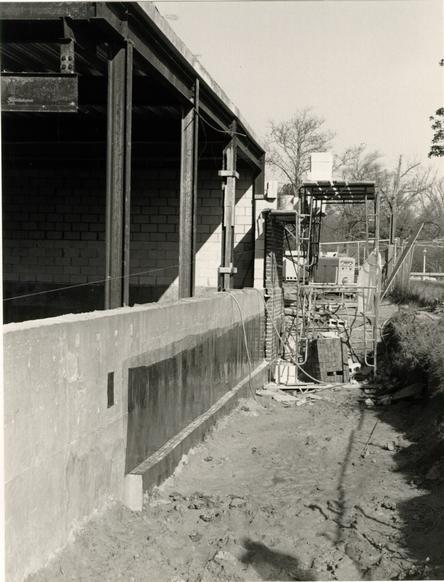 Figure 394
Wallace Gallery construction. (CWF 84-TCM-1042s)
 Figure 395
Wallace Gallery wall showing bituthane waterproof layer. (CWF 84-TCM-1043s)
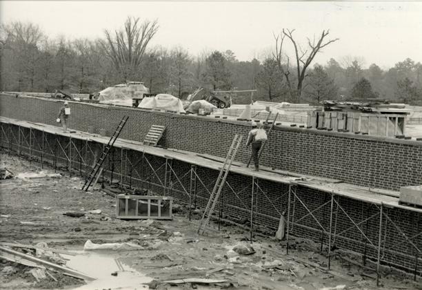 Figure 396
Wallace Gallery construction. (CWF 84-TCM-1074s)
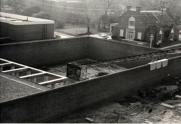 Figure 397
The Wallace Gallery courtyard is excavated for a lower floor. (CWF 84-TCM-2619-37)
CHAPTER XXXVIII
NOTES
CHAPTER XXXIX
MORTAR
PUBLIC HOSPITAL FIELD BRICK MORTAR
Like the history of the reproduction brick, the brick mortar saga is a long and complicated one. This chapter, like all others, will not detail the entire sequence of fifty-nine trial-and-error mortar panels, but will summarize the significant aspects. The complete story, of course, is contained in the minutes and the files.
The earliest experiments in which original hospital mortar was matched to modern samples were conducted by CWF masons using a Flamingo mortar (Fig. 398). In trying to achieve the pure white color of the hospital mortar, taken from the interior of the foundation walls, the makers of Flamingo mortar, the Riverton Company, suggested using a highly refined white silica sand. In addition to a problem with texture, this sand produced an unworkable, "dead" mortar (Figs. 399 - 400). Several more Flamingo ready mixed mortars were used in combination with different sands and shell, including two experimental mortar mixes. After several more samples, a Flamingo mix with white Chickahominy sand was chosen over the "old time" mix used at Colonial Williamsburg. The latter was not a traditional eighteenth-century lime mortar from burned and slacked oyster shell, but one in which cement, lime and sand were separately mixed. With a conventional modern mortar mix, like the Riverton
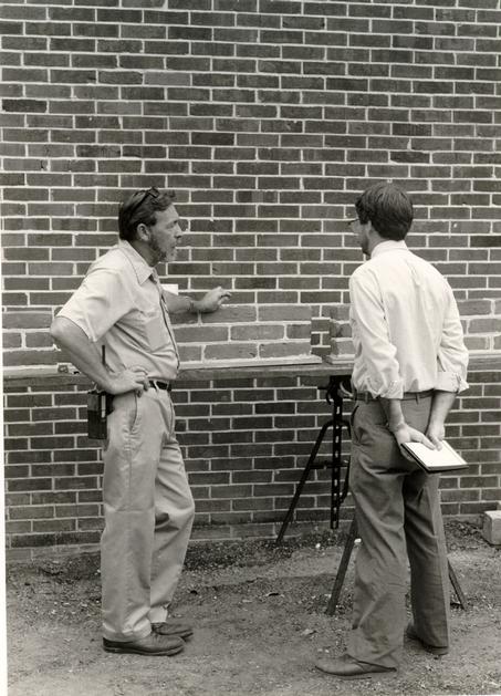 Figure 398
Brick mason Harry Flythe and Travis McDonald examine mortar samples. (CWF 83-1043s-EAC)
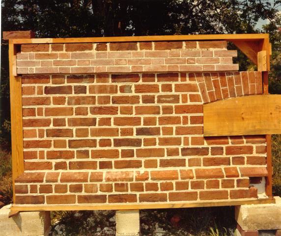 Figure 399
The first full size panel of bricks and mortar. (CWF)
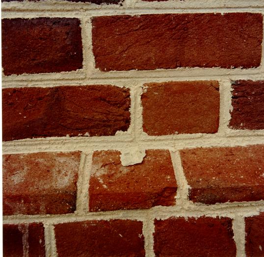 Figure 400
A small chop of original Public Hospital mortar is compared to a sample of Flamingo mortar. (CWF)
389
CEM-192 Trial 2 mortar that was selected, sand is the only added ingredient.
Getting oyster shell to appear in the struck mortar joints proved difficult. It was felt that perhaps any freshly struck joint, even in the eighteenth century, would hide most shell particles until weathering eventually broke down the surface. Increased amounts of poultry shell only seemed to hamper the creation of a deep tool groove. Nevertheless, the shell was added in the event the mortar ever breaks down. This was entirely in keeping with the philosophy of reproducing a "new" mortar, that is, one that would have appeared new on the building in 1773, rather than artificially aging the mortar to look antique, as in so many earlier reconstructions. Arguments for a real oyster shell mortar, for the most authentic weathering potential, were denied for reasons concerning the complexity of preparation. Similarly, recommendations for a real burnt, slaked and ground oyster shell were denied. This latter recommendation had as its intention the inclusion of small white pieces of lime, in addition to shell, seen in real eighteenth-century mortar.
With a tentative mortar selected, Snow, Jr. and King proceeded with the first of their large panels (Fig. 97). Besides a problem with the gauged brick mortar, the mortar's texture remained too grainy when compared to unweathered antique examples. This was believed to be the result of the inherent characteristics of modern mortar mix, namely, the proportion of cementious material to sand. The properties of shell lime mortar 390 were such that a proportionally smaller amount of sand was required, creating a smoother, butter-like joint when struck. In the eighteenth century, George Mason specified mortar consisting of 2/3 lime and 1/3 sand for exterior work at Gunston Hall and equal parts for interior brickwork.1 Mortar for an eighteenth-century town hall in Barbados was also specified to be 2/3 lime and 1/3 sand.2 Smooth joints were achieved on 1930s Williamsburg buildings with three different mortar mixes: 6 parts cement, 10 parts lime and 11 parts sand; 1 shovel white cement, 8 shovels oyster shell lime putty, 8 shovels yellow sand and 8 shovels common sand; and 3 parts white cement, 10 parts oyster shell lime putty, 1 part hydrated lime and 11 parts sand.3 The principal difference today seems to be that modern mortar mixes are much harder due to the absence of lime and the presence of a high amount of cement; also, more sand is added to the overall ration, reducing the more costly cementious ingredient.
By experimenting with a number of different sands such as Gunter, Baillo, a special Gunter, and a Chickahominy, different textures and colors were achieved (Fig. 401). The latter sand was eventually chosen for its whiteness and workability. Some sands, such as Gunter, were beach sands too fine in grain size which produced an unworkable mortar. Another, a red Lone Star sand, produced a beautiful texture but the wrong color. By this stage of the experiments, Snow, Jr. and King had switched to a premixed Atlas white mortar for the various
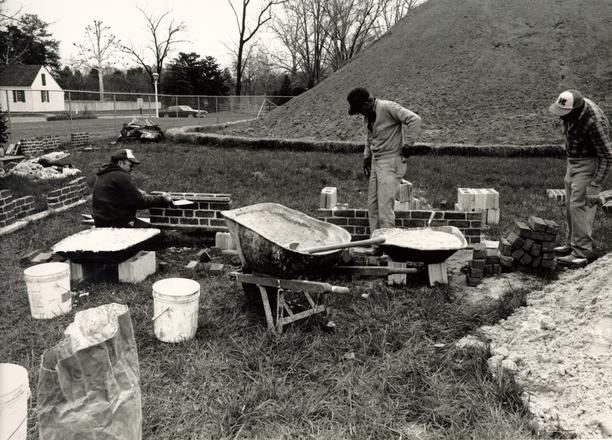 Figure 401
Various combinations of mortar mix and sands were constructed by Earley Thompson of Snow, Jr. and King. (CWF 83-3066s)
391
combinations, generally a 1 ready mix cement-3 sand or a 1 ready mix cement-2 sand ratio with 1/4 or 1/8 parts shell.
Hydrated lime had been used in some of the experiments in a 1 ready mix cement-1 hydrated lime-3 sand (parts by volume) to achieve a smoother texture. The Thomas Taylor then induced the committee to consider an even higher proportion of lime for other reasons.4 By specifying a lower amount of white Portland cement, especially one low in alkalines and gypsum, and by increasing the percentage of hydrated lime, it was felt that problems of efflorescence, thermal expansion and water movement could be minimized. New panels in a 1 cement (Atlas white)-2 lime (Hydrated Miracle Lime Type S)-3 sand and 1/4 oyster shell (#1 size) ratio of parts by volume were then made. Although this mortar formula using a Gunter sand produced a near perfect texture (Fig. 402), the workability of the mortar led to the selection of White Chickahominy sand (Fig. 403).
Questions concerning the low sand ratio of the selected hospital mortar led to further research into earlier CWF reconstruction projects.5 In the 1940s the mortar mixes were 1 cement, 1 "lime putty" and 7 sand. By 1953 CWF Master Specifications called for a 1 part cement, 2 parts lime (hydrated) and 6-8 parts sand. This last formula was similar to the 1C-2L-5S used at the 1976 reconstructed City Tavern in Philadelphia. Theoretically, the increasing hardness in mortars, seen in the reversed superior ratios of lime and cement to sand, can be attributed to the increased hardness of modern kiln-fired
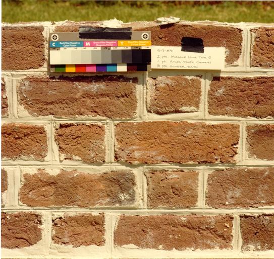 Figure 402
Achieving a buttery smooth texture was as important as a good color match. (CWF K83-FD-312)
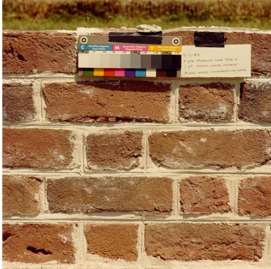 Figure 403
Chickahominy sand was the initial selection for the mortar. (CWF K83-FD-313)
392
bricks when compared to that of traditional, clamp-fired bricks. in clamps.
New experimental panels of 1C-2L-4 1/2S and 1C-2L-6S mixes revealed additional problems of texture and color (Fig. 404). The increased amount of sand logically resulted in a more grainy texture. The discovery of a smooth-textured 1-2-5 mortar mix used at Christ Church, Lancaster led to the conclusion that the solution lay in finding a finer grain sand. The option of screening Chickahominy sand was explored, but the time and cost involved in having a screen custom-made for the sifting machines at Chickahominy was too great. Every sand company between Virginia Beach and Richmond was contacted, and any potentially usable sand was examined. After a futile search, the sand used at Christ Church, Fisher sand from Weems, Virginia, was examined and samples proved successful in a 1C 2L-5S-1/2sh mix. Fisher sand is remarkably white, pure and fine (Fig. 405).6 Laboratory tests concluded that the sand was from a fresh water deposit and thus needed no washing to remove salts.
Each batch of mortar was mixed at the site each day by Herbert "Bear" Moore of the Snow, Jr. and King crew (Figs. 103, 406 - 407). Batches of mortar were divided into a number of shallow trays which were then lifted to the scaffolding by forklift operator Lester Campbell (Figs. 408, 106). Once on the scaffolding, the trays of mortar were continually mixed by Alton Bell (Figs. 107, 108).
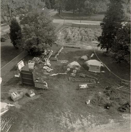 Figure 404
The northeast corner of the site was designated the experimental area. (CWF 83-FD-5509)
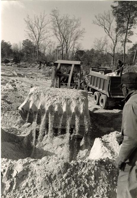 Figure 405
Pure white, fine-grained Fisher sand from Weems, Va. was finally chosen for the hospital and gallery mortar. Each load was carefully watched to avoid veins of discoloration. (CWF 84-TCM-1589s)
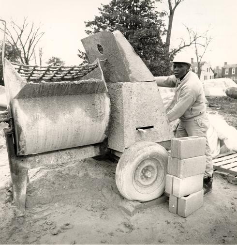 Figure 406
Herbert "Bear" Moore of the Snow, Jr. and King Company was responsible for mixing each batch of mortar. (CWF 84-FD-1718-8s)
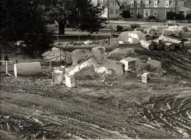 Figure 407
The mortar mixing area was located directly north of the hospital building. (CWF 84-TCM-1065s)
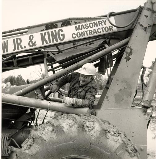 Figure 408
Lester Campbell of Snow, Jr. and King lifted large trays of mortar up to the scaffolding with a fork lift. (CWF 84-FD-1718-6s)
GAUGED BRICK MORTAR
Traditionally, gauged arches and belt courses were constructed with a pure lime putty mortar. This would have been the same oyster shell lime used for field brick mortar but without the sand. A commercial hydrated lime was used for the first gauged brick arch in the hospital panel (Fig. 399). The extremely slow setting or curing time for pure lime mortar, as evidenced by this first panel, was thought by some to constitute a problem, especially for the belt course and the weight of brick resting on it.7 An archival search for old CW gauged mortar mixes yielded a S. P. Moorehead letter of 1937 in which gauged brick mortar used at the Governor's Palace and the Public Records office was defined as a one part lime - one part cement mix. The results of this appeared, at first, to be acceptable, but within a short time the color changed from a chalky white to a shiny off-white and the texture became like marble. Various combinations of lime and cement were then tested until a recipe of one part cement and 10 parts hydrated lime was selected (Figs. 409 - 410). This combination set quickly and had a chalk white appearance.
GALLERY MORTAR
The Public Hospital Design Review Committee was asked to recommend a gallery mortar at the same time they were asked to recommend a gallery brick. To distinguish the gallery brickwork from that of the hospital, both visually and philosophically, the
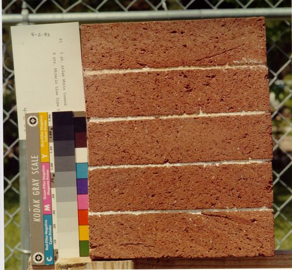 Figure 409
Lime "putty" mortar was tried in various combinations of lime and cement (CWF K83-FD-317)
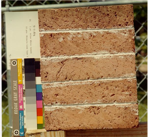 Figure 410
The final combination of lime mortar. (CWF K83-FD-319)
394
committee recommended five design elements for the exterior gallery wall: 1) a brick color range similar to the hospital's but without the plum and dark red shades (the gallery brick was also smaller), 2) a nineteenth-century garden wall bond, 3) a nineteenth-century joint, 4) and no rubbed, gauged or glazed brick.8 See the gallery brick section in Part III for the philosophical discussion of these points.
The brick bond, the Federal style mortar joint and the absence of rubbed and glazed brick were meant to chronologically distinguish the gallery wall as later than the hospital. This was one basic premise in recommending the design details. The other premise was far more subtle. By tinting the mortar brown-yellow, one could play upon the colonial revivalist's use of instantly aged mortar, as in the reconstructions of the Palace and Capitol and many others in Williamsburg. In addition to a practical, visual distinction between the two walls of brick, the wit inherent in using a revivalist detail seemed perfectly suited to a modern museum masquerading as an innocuous brick garden wall.
Using this rationale, the first gallery panel was constructed in January 1983 (Fig. 411). As a guide, the yellow mortar on the east wall of the Merchant Square Craft House was selected as a proper color (Fig. 412). Unfortunately, Kevin Roche failed to appreciate the humor of the yellow mortar and asked for a color to match that of the hospital mortar or to be
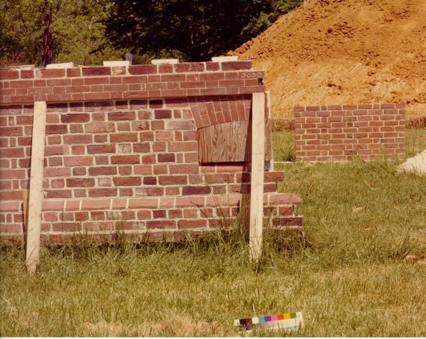 Figure 411
The first gallery panel, to the right, was viewed in context with the hospital panel. (CWF K83-FD-314)
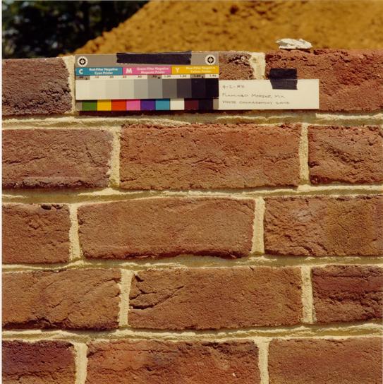 Figure 412
The recommended mortar was tinted yellow and was struck with a Federal ear joint. (CWF K83-FD-311)
395
slightly off-white. However, a Federal style inverted V-shaped struck joint was approved for the gallery.
For the nine months following Kevin Roche's decision on the mortar, experimental gallery panels were constructed in addition to the numerous hospital and gauged mortar panels. After reviewing a series of gallery panels in a 1C-2L-3S ratio, Roche/Dinkeloo decided they wanted a 1C-1 ½L-6S ratio, which prompted still more panels. A successful off-white color was never achieved. In October of 1983 a final gallery mix was chosen: 1C-1 ½L-5S (Fisher Sand) with no oyster shell. In all, twelve separate gallery panels had been constructed.
CHAPTER XXXIX
NOTES
CHAPTER XL
SHINGLES
The first question which arose in considering a roof covering for the Pubic Hospital was whether or not a standard CW cement-asbestos shingle roof could be used. The answer, of course, was no. The stock of Mohawk and Hampton Institute cement asbestos shingles used on virtually every major building in the Historic Area was nearly depleted. The closest substitute was a concrete shingle made by the Hendricks Tile and Manufacturing Company of Richmond. Hendricks shingles had been used on the Custis Maupin House, the Davidson Shop, the middle hip of Casey's Department Store and the Post Office. A quick study of recent wood shingle roofs determined that the concrete product would most likely last twice as long as a wood product. Considering the project manager's request for a roof with the greatest longevity, the committee decided in favor of a Hendricks shingle, provided it would meet our specifications (Figs. 413 - 414).
Thus began a frustrating two-year period in which Hendricks tried to meet those specifications. It was a story of progress and regress, of manufacturing limitations and experimentation, of acceptance and rejection. The first apparent problems were those that tenaciously lingered on throughout the entire manufacturing process: rough edges, misplaced reinforcing wires, obstructed nail holes, improper color, and thickness (Figs. 415-417). In effect, these were problems inherent in the
 Figure 413
A Hendricks concrete shingle roof in place on the Single Brothers Workshop at Old Salem, North Carolina. (CWF 82-5468s-TCM)
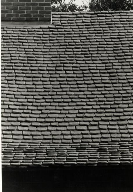 Figure 414
Detail of the Hendricks roof at Old Salem. (CWF 82-5469s-TCM)
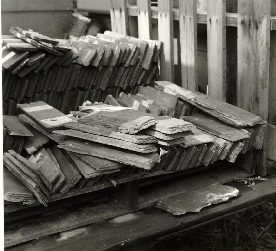 Figure 415
A shipment of sample Hendricks shingles. (CWF 82-DS-3823)
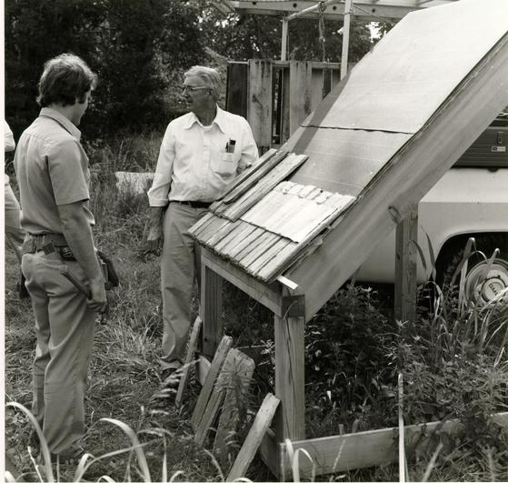 Figure 416
Paul Hurley, right, supervises the installation of sample shingles. (CWF 82-DS-3820)
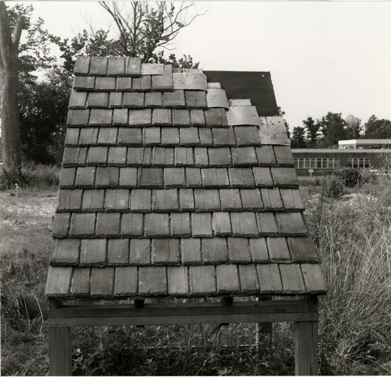 Figure 417
A straight-roof mock-up of Hendricks shingles. (CWF 82-DS-3816)
398
handmade process of manufacturing the shingles. In contrast to the eagerness and optimism with which the brick manufacturer altered his standard process for the hospital bricks, the shingle manufacturer steadfastly and pessimistically let his limitations constrain the product, and ultimately, the project.
Quality control played a major part in the effort. If in one sample the rough edges had been successfully dealt with at the expense of a good taper, the following sample might have exhibited a good taper with rough edges, and so on (Fig. 418). Once the field shingles became seemingly problem free, the hip shingles became the stumbling block (Fig. 419). Mock-up roof structures were ordered for both the field and the hip shingles, with each successive batch of samples replacing the former batch (Fig. 420).
Additional problems plagued the success of acquiring a concrete shingle roof. Copper sisalcraft strip flashing had been recommended for each layer of shingles to ensure additional waterproof protection. The problem with this flashing was twofold. Due to their rough edges, the shingles would not fit close enough to completely hide the flashing. This was a problem because the flashing stayed a bright shiny color unless exposed to the sun. To control the shininess various liquids were applied to the flashing, ammonia being the most effective (Fig. 421). Eventually this solution was replaced by an alternative method of strip layering that placed the flashing out of view (Fig. 422).
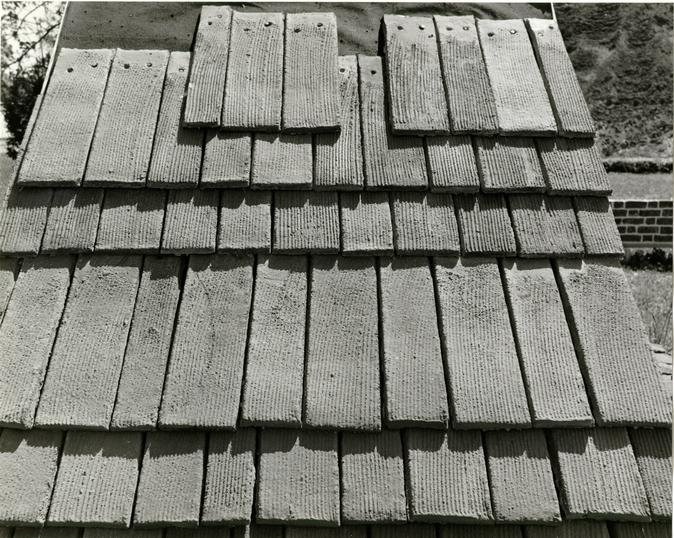 Figure 418
One of the later batches of Hendricks sample Shingles. (CWF 83-FD-1968)
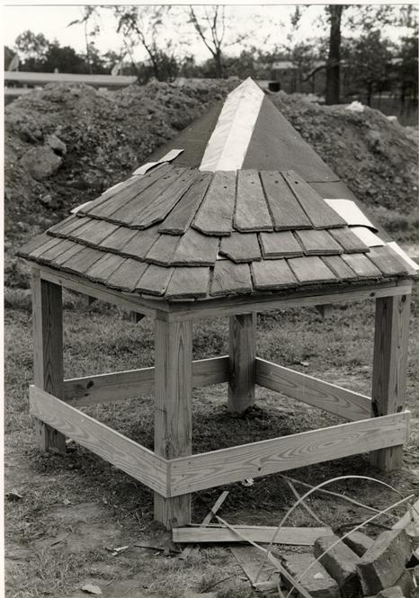 Figure 419
A hip roof mock-up of Hendricks shingles. (CWF 83-1291s-TCM)
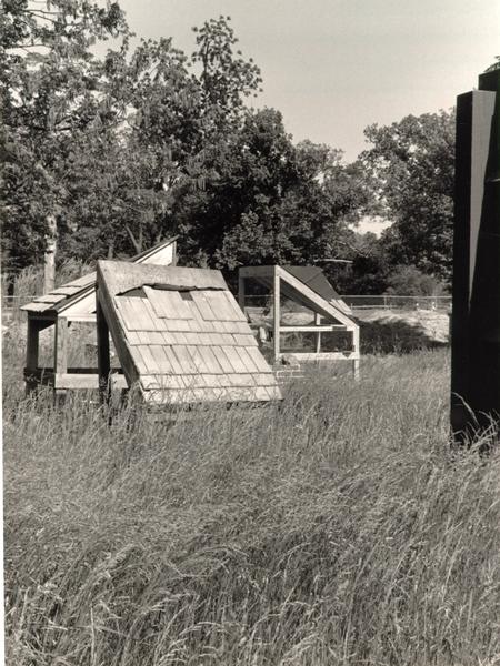 Figure 420
Three roof mock-ups: a straight, a hip and a valley section. (CWF 84-TCM-2318-SO-25A)
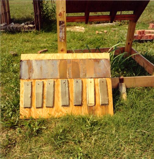 Figure 421
Various coatings of liquid were applied to the copper flashing to dull its shiny finish. The same coating was applied to the shingle to determine if any discoloration might occur. (CWF)
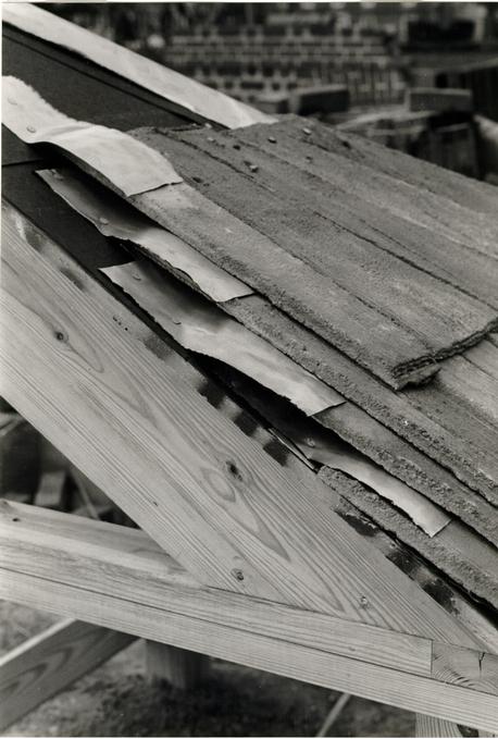 Figure 422
An alternate method of strip flashing was found which kept the flashing from exposure. (CWF 83-1292s-TCM)
Nails proved to be a related problem. Copper nails, typically used in conjunction with copper flashing, would not penetrate the concrete plank deck to which the shingles were to be nailed. Silica-bronze and then stainless steel were chosen as substitutes. The latter was less expensive, stronger, and thought to be compatible with the copper flashing.
After two years of sample reviews, Hendricks started production of the hospital shingles. Two or three days production, equalling approximately one-third of the total order, was examined at the Richmond plant. To the Design Review Committee's great disappointment and frustration, the shingles did not resemble the approved sample. The manufacturing process, it was explained, had been altered and the company owner voiced his unwillingness to experiment or expend any further effort on the product. One final sample of culled shingles was brought to Williamsburg but even these were not without problems. Considering this setback, the lack of quality control, the yet unresolved problem of fantail hip shingles, and the anticipated problems of installation, the committee turned to the possible use of wood shingles.1
WOOD SHINGLES
Switching roof materials at such a late date in the project was not without serious and unforeseen repercussions. Reversing an earlier compromise was one of the exciting advantages of the change. Wood shingles not only work much 400 better in creating fantail hips, tympanum weatherings, round butts, and cupola roofs, but made possible authentic swept valleys as opposed to the open flashed valleys specified with concrete shingles. On the disadvantage side, we had to produce a large quantity of shingles in a short time, with many lessons to be learned about the material, tools and process of handmade heart cypress shingles and their installation.
The first three questions to be addressed were a) would the city approve a wood roof on a major exhibition building; b) what were the handmade shingles to look like; and c) who would make them. Initially crucial, of course, was city approval. In order to discuss the issue with the city's building code board, a number of issues had to be resolved. Did we want commercially available shingles or handmade shingles? After obtaining a number of machine sawn cypress shingles from the Corbitt Cypress Company in Jasper, Florida, a comparison with hand split/hand finished shingles was made and the latter were highly favored. The uniform appearance of the machine sawn shingles resembled plywood at a distance. Another deciding factor was the material. Sawn cypress shingles are cut from the entire log, both sapwood and heartwood, resulting in an inconsistent longevity rate. Hand produced shingles, on the other hand, utilize only the heartwood.
Knowing that the city would almost surely insist on fire-retardant shingles, experts at the UL Laboratory in Illinois were asked about treatment. Pressure treatment was the only approved method and the Koppers Company was recommended for the 401 work. Koppers had neither tested nor rated cypress as a roof covering; its experience was limited to cedar. Testing a new material was not only time consuming, but extremely costly for the buyer. The approach then taken was to determine the similarity between bald or southern cypress (Taxodium distichum) and western red cedar (Thuja plicata), which carried the label rating.2 In response to this question, a professor of forest products at the V. P. I. School of Forestry stated that the only cellular difference between the two species was the size of the trachea and that there was a higher probability of chemical leaching in the cedar.3 This information convinced the city to grant a variance on the non-classified roof covering, provided the shingles were treated and met the requirements of a Class C roof. In addition, the nailing strips had to be of fire-retardant lumber.
As it turned out, Koppers would not accept an owner supplied material for treatment. Luckily, however, Hoover Universal in Milford, Virginia, operated a pressure treatment plant for wood products, including shingles.4
DOCUMENTATION
In addition to the previous documentation used for the concrete shingle specifications, it was necessary to closely examine surviving eighteenth-century shingles to determine their characteristics. Cypress was, by far, the most commonly specified material for shingles, with pine, poplar, chestnut, oak 402 and cedar called for in descending order based on a survey of over fifty examples.5 Some of the other characteristics were also very common: a length of 18", exposure of 6", and ¾" thickness at the butt. Widths are seldom mentioned in specifications. One notable exception is a 1701 reference to St. Peter's Church in New Kent County where the shingles were specified to be between 3" - 5".6 This information was corroborated by a survey of surviving shingles on the earliest part of the Peyton Randolph House roof, where 94% of those measured ranged between 3" - 4 ¾".7
To determine the minor details of hand-finishing, the committee first examined extant shingles from the Mt. Airy dependency, Wetherburn's Tavern, Bacon's Castle outbuilding, and Blandfield. The latter, in particular, was an important example because it had never been exposed to the weather, as it had been used as a shim during installation of the first roof. All of the examples exhibited smooth planed sides, tops and bottoms; all tapered to a feather edge. The taper was found to have a greater angle on the top third of the shingle. Some of the round butt examples obviously had been rounded by hatchet, others by drawknife. This method of rounding the butt became clear when CW craft carpenters compared some newly made round butt shingles with the antique examples.
With the change in materials came a change in form from square to round butt. The rationale for this change is best explained in a memorandum from Edward Chappell, which included 403 extensively documented examples (only portions of the text are quoted here--for the annotated samples consult the actual memo):
You may remember that when we changed from concrete to cypress shingles for the Public Hospital roof, we also changed from square-butt to round-butt shingles. There were both practical and interpretive reasons for the initial choice of square-butt shingles. First, we suspected that Hendricks might be unable to supply rounded shingles of the necessary quality. Secondly, I suggested that square butts could be more appropriate for a late colonial public building, a building that might well reflect the general trend away from expression of individual components. When we finally discovered that Hendricks could not supply a reasonable product, whatever its shape, we had an opportunity to reconsider our initial premise. Because considerably more fieldwork had been done by that point, we recognized that although there was indeed a shift of emphasis away from building components (such as glazed brick, extensive use of rubbed and gauged brick, elaborate expression of chimney caps, raised paneling, etc.) by about 1800, almost all known late eighteenth and early nineteenth-century roofs had round butt shingles. As a result, the committee decided that it was most appropriate to use round-butt shingles as part of a full-blown reconstructed roof, with all the subtleties of riven and drawn shingles, swept valleys, fantailed hips and cupola facets, and a combed ridge.
While we assume that square-butt shingles may have represented a fairly common eighteenth-century roofing option, possibly slightly more economical than roundbutt shingles but more costly than board roofs, we know of only four surviving early examples. Closest to home are the apparently earliest roof covering of the Benjamin Waller House and the first-period M roof of the Peyton Randolph House, the latter preserved below a second-period roof. Most of the Peyton Randolph shingles survive on the hidden inner slopes, and these are square butt. We are told that square-butt shingles also survive on the inner slopes of a similar first period M roof at Homewood in Baltimore. Perhaps more relevant to the Hospital is the circa 1770 Ridout House in Annapolis, which at an early date had a square-butt shingle roof rising visibly above parapets. Large numbers of the wrought-nailed shingles remain in place on the lower slopes, protected by an early nineteenth-century alteration of the roof line. The Ridout House shingles are extremely regular in size, and they--as 404 well as other aspects of the house--seem to be responding to the aesthetic change noted above.
Nevertheless, the Ridout House example seems overwhelmed by the quantity of Chesapeake buildings with round-butt shingles. The examples provide an extensive range, from small outbuildings to houses comparable in scale and finish to the Public Hospital. A list of currently known examples follows, with sources noted. Large late colonial gentry or merchant houses such as Blandfield, Landsdowne, Mt. Airy, and the Carlyle House are most directly relevant, but the presence of shingles nearly identical to those used for the Public Hospital on the circa 1830 roof of Venable Hall at Hampden-Sydney is also informative.8
SHINGLE PRODUCTION
Shingle making at Colonial Williamsburg by the 1980s, like brick making, had dwindled to a small scale demonstration process. In recent cases where an outbuilding roof had been replaced, hand-split/resawn shingles of western red cedar were purchased and then reworked into a finished shingle. Useful information regarding large-scale production, such as the estimated number of heartwood shingles per 1000 board feet, was nonexistent. This lack of information led to an unfortunate reliance on the greatly underestimated quantities of time and materials given by a shingle maker in Maine, who had been contacted for the job. Moreover, when the realistic quantity and quality of cypress slowly became known, its acquisition proved to be one of the most problematic aspects of the project. Another unforeseen problem was the length of time to produce sixty-three squares.
Colonial Williamsburg's own craft carpenters could not undertake the shingle production because of their involvement 405 with the James Anderson Forge reconstruction. After several attempts to find both local cypress and shingle craftsmen, suitable cypress logs were located at the Evelyn Piling Company of Providence Forge and two craftsmen from Dryden, Maine, expressed interest in the job.9 Before making a commitment to these men in Maine, Louis Thibault and Douglas Wilson, two 36" wheels of cypress were sent to Maine for their use in producing sample shingles. This was necessary not only to obtain samples, but because Thibault and Wilson had never worked with cypress, which is not available in Maine. With the delivery of the first six logs in January, 1984 (Fig. 423), and the arrival of Thibault and Wilson the following month, shingle production began in a vacant bus garage on Botetourt Street.
Finding both the right quantity and the right quality of cypress became an unexpected nemesis throughout the entire project. To begin with, the total quantity was underestimated. It had been hoped that by sending two complete "wheels" of cypress to the shingle makers in Maine, their estimate would be close to accurate. In reality, a production analysis after the first two weeks led to a total cost and material projection that exceeded the original estimate by approximately eight to ten times.10 In addition to the increased material cost, the production fee per square had been increased; there was a labor cost for cutting the logs into wheels; and the original three weeks production time was projected to thirty weeks, increasing the per diem and lodging costs. Most shocking was the jump in
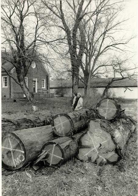 Figure 423
The first six cypress logs were delivered to a lot on Franklin Street. The bus garage in the background contained the shingle production area. (CWF 84-TCM-1686s)
406
material. With even the best quality logs, the finished shingles accounted for only 15-25% of the total board feet, varying according to the relative size of sapwood and heartwood. A production analysis after eighteen squares revealed that the average quantity of cypress needed to produce a finished square of shingles was 800 board feet.
After exhausting local suppliers of cypress, the search extended to virtually every lumber company and sawmill in Tidewater Virginia and North Carolina.11 A great complicating factor was the timing of the project. Seasonally, cypress should be sought in the summer or early fall when the swamps are dry enough to get to the trees. By winter, the trees can't be reached and the previously cut trees have been sawn into lumber. When the initial excitement of locating a source of cypress logs wore off, the seemingly straightforward method of selection became a game of chance, betting against a law of averages (Figs. 424 - 425). Logs were selected for all the obvious criteria: large diameter with a large percentage of heartwood; straight, non-twisted bark; and an absence of limbs (Figs. 426 - 427). Twisted bark and limbs were sure signs that the inside grain would be twisted and useless for splitting. Generally, these factors called for selecting the second and third cuts from a large tree, and possibly the butt cut, although the latter typically contains a rather useless undulating perimeter surface. Despite some success in acquiring the art of recognizing telltale parallel growth ring cracks on the cut ends, many selected logs
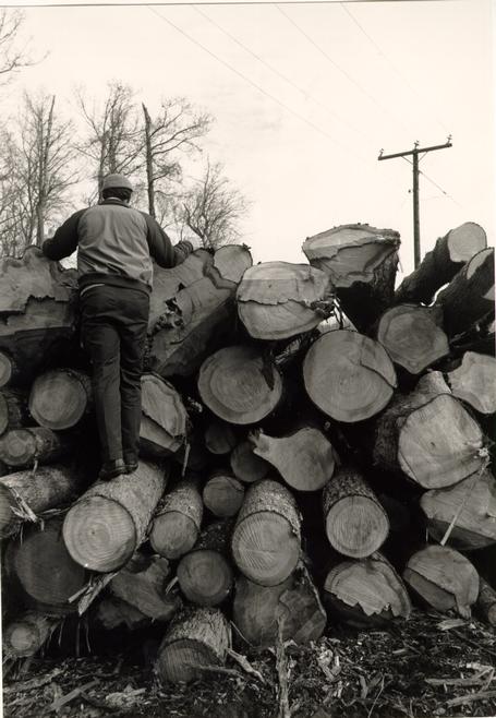 Figure 424
Mark Berninghausen helps in the selection of the first cypress logs at the Evelyn Sawmill Company in Providence Forge. (CWF 84-TCM-1060s)
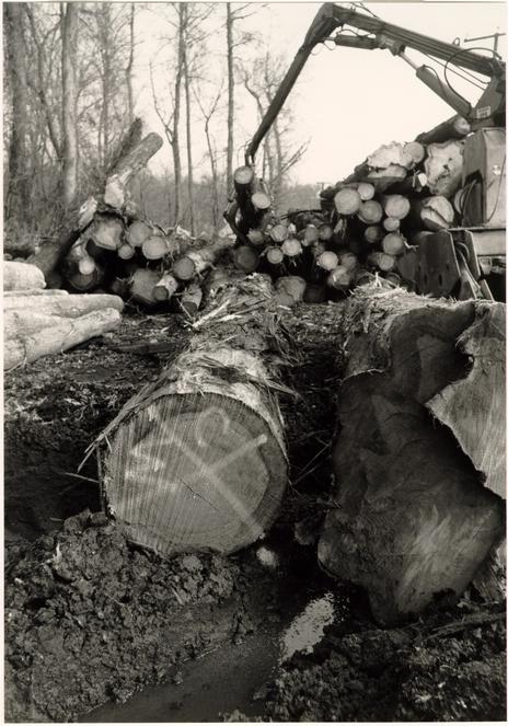 Figure 425
The selected logs were culled from large stacks and marked. (CWF 84-TCM-1063s)
 Figure 426
Cypress logs from North Carolina arrived at the site by truck. (CWF 84-TCM-2568-9a)
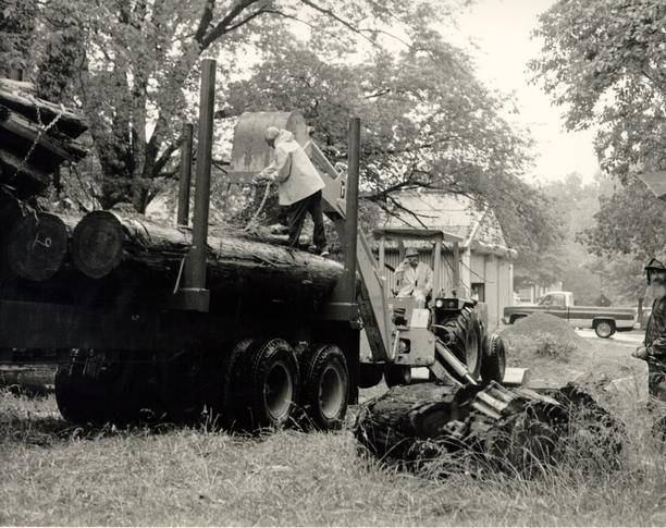 Figure 427
Without the proper equipment the logs were unloaded with difficulty. (CWF 84-TCM-2565-11A)
407
turned out to be unworkable. It became very discouraging to buy logs with all outward appearances of perfection only to find their heartwood twisted, dry or peggy. Unfortunately, by the time these faults were recognized, the logs had become rather expensive firewood.
During times of material shortage, various alternative techniques were tried on the pieces that could not be hand split. One such method involved having logs sliced into 1" boards at the sawmill and then cut into 18" pieces that could then be hand finished. One such log was too large for the sawmill carriage; the shingle makers simply went to the sawmill site and removed the sapwood by wedges. Another technique for splitting "wheels" that were so tough the wedges had to be cut out was to use a conventional, gasoline-powered firewood splitting machine. Fortunately, for reasons of authenticity, the number of shingles produced by these methods accounted for only a very small part of the total.
One of the most superior trees happened to be the most local. Magnificent cypress trees were known and located on the Carter's Grove property, but their beauty was felt to be more significant than their transformation into shingles (Fig. 428). Fortuitously a very large cypress tree was found to be perilously close to the Carter's Grove reception center bridge spanning the ravine. The tree was felled and provided two excellent straight grain logs for the project (Figs. 429 - 430).
 Figure 428
A cypress tree which stands in the pond at Carter's Grove. (CWF 84-TCM-2608-34)
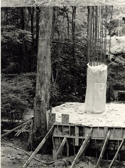 Figure 429
This cypress tree was found to be too close to the Visitors' Center bridge at Carter's Grove and was carefully cut down for shingle production. (CWF 84-TCM-2608-36)
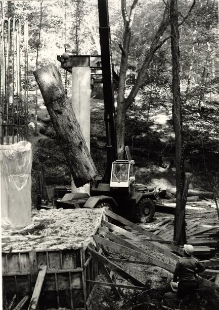 Figure 430
The Carter's Grove tree was carefully removed to avoid damage to the bridge supports. (CWF 84-TCM-2459-15s)
The shingle making team began as a two person operation with Louis Thibault and Douglas Wilson from Maine (Figs. 431 - 432). For reasons stemming from his personality, Louis quit after six weeks and returned to Maine. By this time, April of 1984, two local men, James Stewart and Anthony Morning, were trained to work along with Doug. Michael Dandridge joined the group in December and the four-man crew worked together until March 1985, when the final, the sixtieth, square was finished (Fig. 435). Doug Wilson returned to Maine at that time. The others continued working, creating a surplus of nine squares. Single production stopped on June 7, 1985, the one hundredth anniversary of the Public Hospital's destruction by fire.
Shingle making, as practiced for this project, is a seven step process. The first step, after delivery of a 12' to 16' log to the site, was to cut the log into 18" "wheels" (Fig. 434). The cutting of these log sections with a chain saw was the only nontraditional step in the process. Step two involves the use of a sledge hammer and wedges to remove the sapwood and split the "wheels" into billets roughly six to eight inches square. These billets were further reduced to 1" - 1 ½" shakes by use of a froe and mallet in step three (Figs. 435 - 436). A hatchet was used in step four to help reduce the thickness and to reduce the width (Fig. 437). Step five involved the use of the shaving horse, which held the shake as it was smoothed and tapered to the proper thickness. In addition to a regular drawknife, a custom-made drawknife with a dipped middle was used to rip down thick
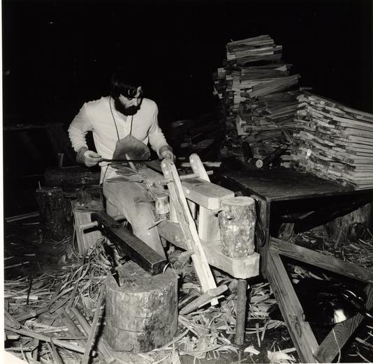 Figure 431
Louis "Joe" Thibault works at his custom shingle horse with its attached upside down block plane for smoothing the shingle sides. (CWF 84-DS-21102, 2s)
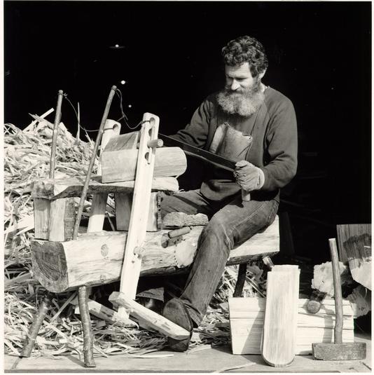 Figure 432
Douglas Wilson rounds the end of a shingle on his zoomorphic bench.
 Figure 433
From left, shingle makers Anthony Morning, Douglas Wilson, Michael Dandridge and James Stewart. (CWF 85-Fd-40-3A)
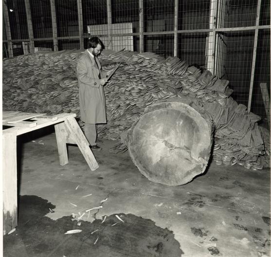 Figure 434
Travis McDonald examines a shingle from the growing pile. (CWF 84-DS-2102-7s)
 Figure 435
James Stewart uses a mallet and froe to split a billet into wrought shakes. (CWF 84-TCM-2658-11)
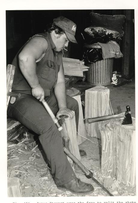 Figure 436
James Stewart uses the froe to split the shake from the larger billet. (CWF 84-TCM-2658-9s)
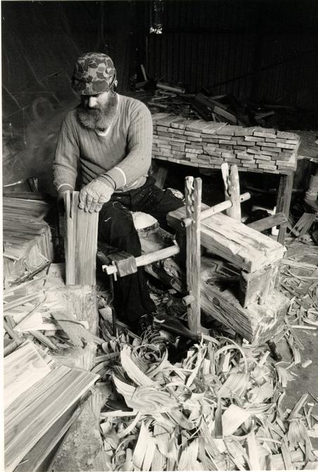 Figure 437
Douglas Wilson uses a hatchet to narrow the width of a rough shake. (CWF 85-FD-40-16A)
409
sections of shakes (Fig. 438). The next-to-last step was to run the sides of the shingle over an upside down plane to produce straight sides (Fig. 439). Finally, step seven was the rounding of the butt with drawknife (Fig. 440). Finished shingles were then stacked or put on pallets to dry.
INSTALLATION
The last step before installation was a fire retardant treatment. One square of shingles had been sent to Milford, Virginia in April to determine if there were likely to be any adverse effects. A major concern was whether the kiln trying treatment would make the shingles brittle and prone to cracking when nailed. This first batch of treated shingles was used on the tympanum weathering with no problems. The lesson learned from the test square, of which half was lost in transit, was the necessity of covering the banded and palletized shingles with chicken wire to prevent any from coming loose.
The change in shingle material affected the shingleroof interface in several ways. First, it was recognized that the shingles could not be applied directly to the concrete roof deck. Shingles must have an air space underneath to facilitate drying, thereby increasing their longevity. Traditionally, shingles were applied to sheathed boards nailed across roof rafters, which allowed plenty of attic air to quickly dry wet shingles. The solution at the hospital was to nail 1" x 2" lath strips to the roof on 6" centers. These fire-treated cypress
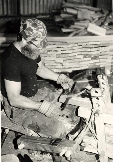 Figure 438
Douglas Wilson uses a "ripping" drawknife to quickly reduce the thickness of a shake. In the foreground is a block plane turned upside down for finishing the shingle's side. (CWF 84-TCM-2658-13A)
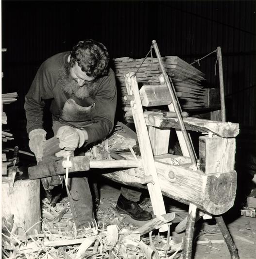 Figure 439
Douglas Wilson runs the side edge of a shingle over the block plane. (CWF 84-DS-2104, 10s)
 Figure 440
The final process is that of rounding the square butt with a drawknife. (CWF 84-DS-2104-10s)
410
strips were applied in a noncontiguous manner with 1" spaces (Fig. 441). To provide drainage, each lath strip was cut with a 5 /16" deep x ¼" wide back kerf every 4". For related reasons of drying and longevity, the strip-flashing that had been specified for the concrete shingles was deleted for wooden shingles. Upon the recommendation of Colonial Williamsburg maintenance personnel, 8" copper sisalcraft strip flashing was retained for the hips, valleys and ridges (Fig. 442). In addition, these areas and the eaves had a strip of lead-coated copper flashing. The cupola shingles were nailed directly onto the bithuthane covered plywood roof without the use of lath strips (Fig. 443). Here, the cupola sisalcraft flashing was applied under each row of shingles.
The most significant change occurred at the cornice. It was recognized that the shingle lath would raise the shingles above the level at which they were to rest on the cornice crown molding. This problem was solved by the addition of a blocking member behind the crown molding fascia. A full discussion of this is found in the cornice chapter.
With the delivery, in August of 1984, of twenty-five squares of treated shingles, a crew of three men from Martin Roofing Company of Richmond began installation on the east side (Fig. 444 - 445).12 Work progressed slowly at first with relatively few problems. The fantail hip shingles (Fig. 446) became one of the first difficult parts, but the chief problem areas were the valleys. Roof valleys were traditionally either
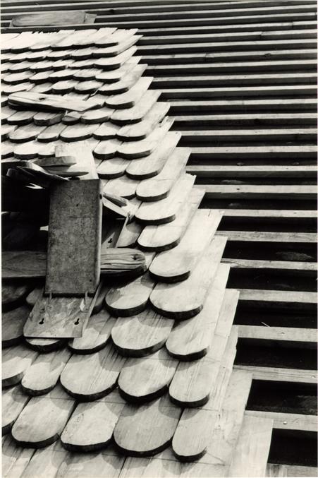 Figure 441
Shingles are applied directly to the lath strips which were nailed to the concrete roof planks. (CWF 85-TCM-1126, 3s)
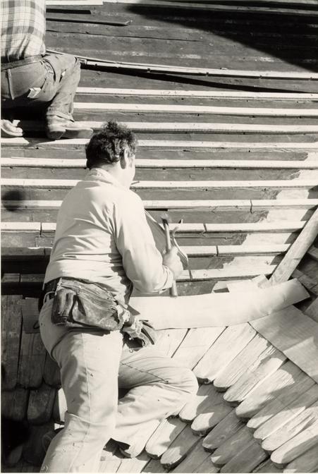 Figure 442
CW master carpenter Tony Meyers placed copper flashing under each row of valley shingles. (CWF 85-TCM-341-34A)
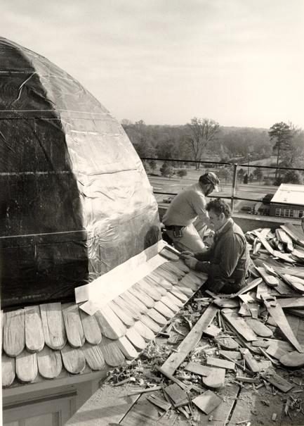 Figure 443
Don Chauput (left) and Tony Meyers use copper flashing for each row of cupola shingles which are nailed directly onto the roof without lath strips. (CWF 84-TCM-2615-22s)
 Figure 444
Fire-treated shingles are unloaded at the hospital site. (CWF 84-TCM-2240-4s)
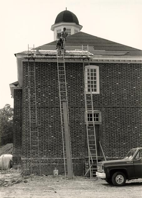 Figure 445
Most of the shingles were installed with this inadequate scaffolding. (CWF 84-TCM-2240-33s)
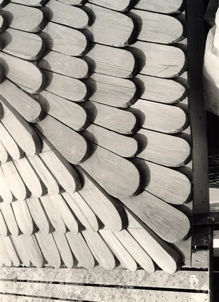 Figure 446
Hip shingles were individually cut for a fan sweep. (CWF 85-TCM-1053-16As)
411
"swept" with shingles or flashed. No extant swept valleys were known, so only a few photographs provided the prototype for a roof valley mock-up (Fig. 447).13 One extra benefit of the mockup was the demonstrated need for a valley board, that is, a 1" x 4" board with bevelled sides attached to the middle of the valley as a nailer for the shingles which also allows them to "roll."14 Despite a demonstration by CW carpenter Tony Meyers of how to shape valley shingles with a hatchet, the roofers repeatedly failed to learn the proper technique. In addition to their insistence on using a power saw rather than a hatchet to shape the shingles, the sweep of the shingles across the valley was being accomplished by one or two large makeup shingles instead of each one providing a gradual turn. After much frustration on both sides and numerous directives to rebuild, the situation was alleviated when Tony Meyers began installing the valleys (Figs. 448 - 449).15
The most difficult part of the shingle installation was the cupola roof with its curve and octagonal hip facets (Fig. 450). Tony Meyers, assisted by Don Chauput, did an excellent job of hand shaping each shingle with a hatchet (Fig. 451). Each course was strip flashed, one layer deep, with ammonia first applied to the sisalcraft flashing to dull its shiny finish.
The last shingles were placed on the roof April 25, 1985, completing one of the greatest efforts of reproducing a building material for Colonial Williamsburg (Figs. 452 - 456).16 A total of about 100 12' - 16' logs were used for the project,
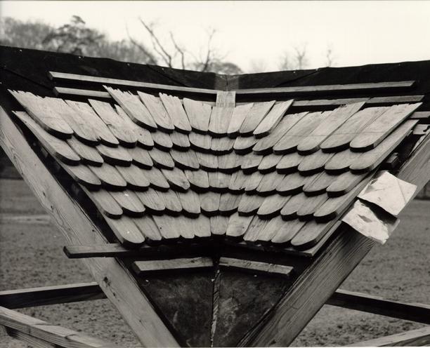 Figure 447
Valley shingles were first worked out on a roof mock-up. (CWF 84-TCM-2658-35s)
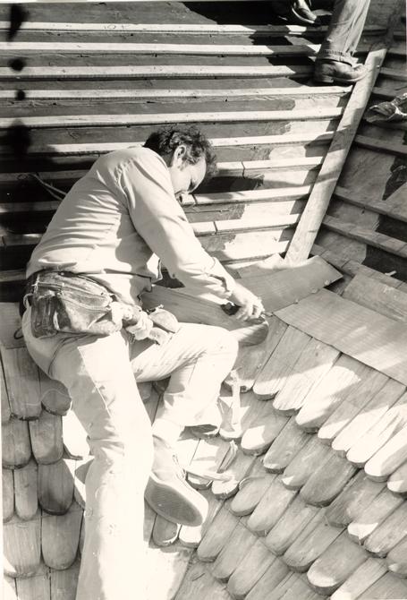 Figure 448
CW master carpenter Tony Meyers individually shaped each valley shingle with hatchet and plane for its fantail fit. Note valley board. (CWF 85-TCM-342-37)
 Figure 449
The most difficult part of the roof was where the south pavilion's hip roof created a ridge next to a valley. (CWF 85-TCM-1053-12As)
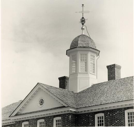 Figure 450
The finished cupola roof. (CWF 85-FD-407-3)
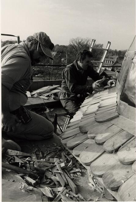 Figure 451
Don Chauput and Tony Meyers shape and install the cupola shingles for both a horizontal and a vertical fit. (CWF 84-TCM-2615-29)
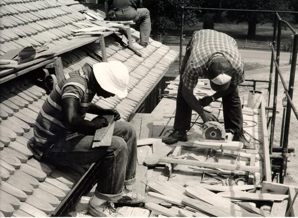 Figure 452
The subcontractor's roof crew shape and cut hip shingles. (CWF-85-TCM-1053, 14AS)
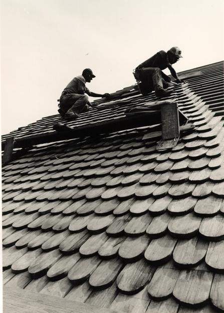 Figure 453
Shingles are installed in horizontal as well as vertical sections to maintain straight lines. (CWF 85-TCM-1126-26s)
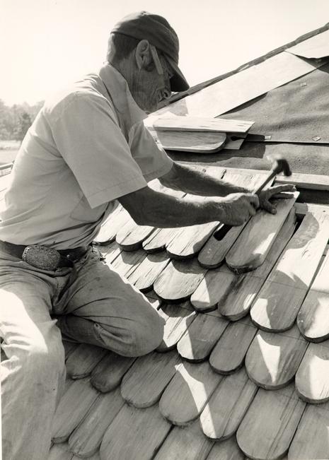 Figure 454
Due to the 3"-5" variation in width each shingle is selected for its location in order to provide maximum cover for the juncture of the two shingles beneath it. (CWF 84-TCM-2460-32)
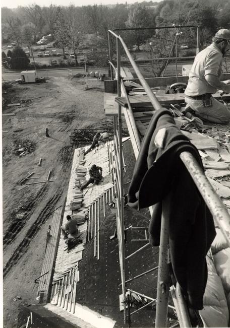 Figure 455
Field shingles are applied below while the cupola is shingled above. (CWF 84-TCM-2615-28)
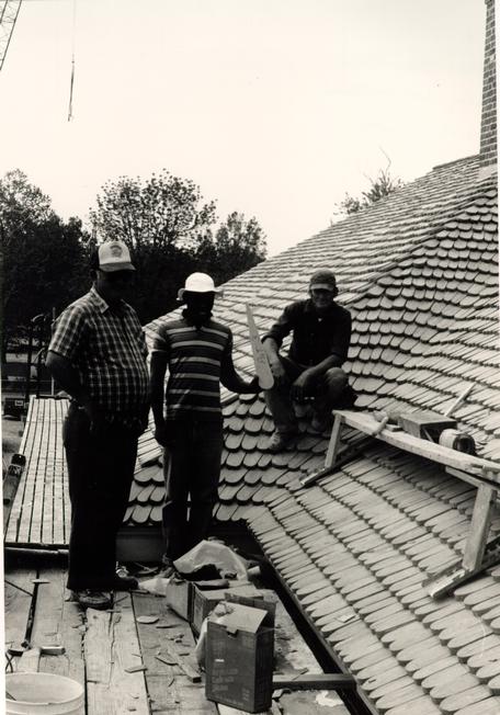 Figure 456
The roofing crew for field and hip shingles from the Martin Roofing Company of Richmond. (CWF-85-TCM-1053, 31AS)
412
totaling about 43,300 board feet.17
CHAPTER XL
NOTES
An undated draft report on the Benjamin Waller House in the block and building files states that parts of the earliest roof on the northern section was of 'random-cut oak shakes,' apparently implying square-butt shingles. Round-butt shingles, thought to be later, were also found during restoration.
CHAPTER XLI
PAINT
DOCUMENTATION
Like many other finish details, paint was not included in Smith's or Powell's specifications. Specifications for Smith's St. Peter's Church in Philadelphia, 1758, called for three finish coasts of paint "a good stone colour."1 Taking into account regional preferences, this color from one Smith building was not used for the hospital. Later hospital records do not clarify the question of paint color absolutely although an 1803 account of supplies furnished by John Greenhow suggests the color white. That account lists white lead, lampblack and Spanish brown as paint colors, white lead being by far the greatest quantity.2 This suggestion was strengthened by research into the probable exterior colors of public buildings in Williamsburg.3 The two most comparative public buildings were the Church and the Courthouse. A report on the former yielded a reference that original trim had been found and it had been painted an off-white. The Courthouse had lost all of its original woodwork in the fire. For undocumented reasons the Palace, the Public Record's Office and the Capitol have trim painted a tan color. For domestic buildings the only documented paint analysis comes from the Wythe House where in 1939 the restoration architects described the original trim color to be "pure white" and the door 416 to be "dark brown."4 This record, along with church vestry records calling for a Spanish brown primer and white trim, influenced the Committee to choose a Spanish brown primer; off-white for the exterior. trim finish coat; and dark brown for the doors. Conclusive information would only come from professional paint analysis of public and domestic buildings in the Historic Area. This was recommended several times in a two-year period, but never commissioned due to a lack of funding. The colors selected were Martin Senour Spanish brown (CW #1079); white (CW #10YR); and brown (CW #168). These were called out in the specifications to be an oil base primer and an oil base finish coat.
Millwork samples revealed a problem with the prime coat. In order to retain their characteristic properties, primer can only accept so much of a paint pigment coloring. In our case the dark reddish-brown Spanish brown came out as a pink color. While it was important to retain the protection offered by a prime coat, it was also important to have a proper Spanish brown color under the two finish coats of white. The solution was to apply the intermediate coat of Spanish brown after the prime coast, increasing the total number of paint layers to four.
Paint used in the Historic Area had taken on new importance in the 1980s. Textured appearance was a crucial concern of the Historic Area Standards and Practices Committee, whose recommendations called for the return to oil rather than latex paint. Accordingly, the hospital was specified to receive 417 oil base paint. The first Spanish brown paint to be applied to the building, on the cupola, raised alarm. The paint suspiciously resembled latex but Construction Management stated that the contractor was using the proper oil paint.5 This early concern effectively stilled any further fears and the painting proceeded through the two finish coats (Fig. 457). In September, 1984, the painting contractor was discovered to have used latex instead of oil for all the wooden trim of cornice, windows and doors.6 The painter had referred only to the gallery and not to the hospital specifications. The millwork shop, however, had correctly read the specifications and used an oil base primer for all the wood, over which the latex had been applied. The general contractor acknowledged the error but took the position that the paint manufacturer saw no harm in latex on oil primer or in a subsequent coat of oil over latex. As a matter of principle as much as authenticity, the Design Review Committee steadfastly asked for the removal of the latex paint. As a matter of expediency, the project manager allowed the incorrect paint to remain.7 Because of the unsightly mildew-infested cornice (see cornice chapter), parts of the trim were repainted in the correct off-white oil paint. The doors received an oil base finish coat over the oil base primer.
The exercise yard fence lumber was painted with an oil base Spanish brown prior to construction and received a second coat after construction.
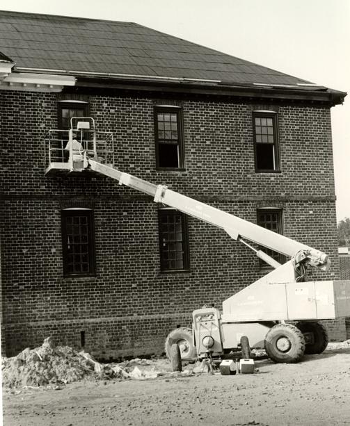 Figure 457
The cornice and the windows were painted with the assistance of a special lift. (CWF 84-TCM-2610-16) 418
Exterior ironwork, including the weather vane, lightning conductor and fence hardware, was primed and painted with a glossy black oil base paint.
Paint for the nineteenth-century apartment was identified through a microscopic analysis of three Western State Hospital paint chips. Because the chips were from a cell at the 1820 building, the third identifiable paint layer, a dark slate gray, was chosen. This was matched under the microscope with a Munsell chart chip, Munsell number 5PB 3/1.8 A large paint chip sample of this color was obtained from the Macbeth Company, a division of Kollmorgen in Baltimore, and used for a color match in the CW paint shop.
CHAPTER XLI
NOTES
CHAPTER XLII
GLASS
The Design Review Committee's first possible source for window glass was the nineteenth century Albemarle Hotel in Charlottesville. This source was quickly rejected, however, for philosophical reasons. The committee in no way wanted to encourage the salvage of architectural materials that might lead to destruction of useful buildings. Efforts were then turned toward finding a reproduction crown glass. original examples of eighteenth-century crown glass were shown to American manufacturers of facsimile glass. Samples from the Blenko and Bendheim companies were examined and rejected as uncharacteristic of crown glass. At this point, the committee decided in favor of a completely modern glass from Binswanger rather than using a poor reproduction. However, it was not satisfied with the Binswanger glass because it was extremely flat and would have given the facades a rather dead quality.
Three additional sources then became known: the Hollander Company in New York which supplies imported glass from Germany, France and Holland; the Bienenfield Company in New York which offers imported German glass; and the Hetley Company in England. Samples were received from these sources and rejected due to non-concentric striations and/or poor refractive quality.
Coincidentally, as we waited for yet another English sample before accepting to a modern plate glass, the Foundation 421 was offered the glass from a turn-of-the century Beaux-Arts apartment building in Washington, D. C. The Wyoming Apartment Building, located at Columbia Road and Connecticut Avenue, was built in three stages from 1900-1911. All the one-over-one sash were to be replaced with new thermal pane windows. After examining this glass, the committee agreed to use it since its refractive quality was good and because it would not be confused as a reproduction crown glass. Those who know glass and its characteristics will recognize the lack of striations and seeds. The refractive effect, however, when walking past the building and when looking through its windows, was important. The committee justified the use of this "antique" glass because its removal was a foregone conclusion, the building was not being destroyed and all efforts to find a suitable modern reproduction had failed. To have used a flat modern glass would have greatly compromised the visual effect of the building.
A thousand 8" x 10" panes were ordered to be cut from the sash, the majority of which were 33" square. Due to breakage in shipment, and the inclusion of some modern glass that had been cut, the total number of panes was inadequate and additional sash had to be cut. Each piece of glass was culled at the TMS Millwork Shop in Richmond and graded as first quality, suitable for the north elevation, second quality for the east, west or south elevations, or unsuitable for the building.
A number of uncut Wyoming Building sash were bought for unspecified use by CWF and put in storage.
THE PUBLIC HOSPITAL:
AN ARCHITECTURAL HISTORY AND
A CHRONICLE OF RECONSTRUCTION
Architectural Research Department
Colonial Williamsburg Foundation
Williamsburg, Virginia
1986
CHRONOLOGY OF PUBLIC HOSPITAL RECONSTRUCTION
Travis C. McDonald
| 11 May - 29 | May Orientation, study and research by TCM |
| 2 June | James S. Tuley (JST) at CW to discuss the beginning of the project and to leave his "Working Drawing Mockup." |
| 3 June | First meeting of the Design Review Committee: Roy Graham, Ed Chappell, Donna Hole and Jim Waite. First details approved for JST (Memo to JST from TCM 3 June 81). Six drawings by Jim F. Waite (JFW) given to JST along with a detail drawing of brick. |
| 4 June | TCM and Roy E. Graham (REG) at Charlottesville to deliver first details to JST. Chapter One of Gibbs/Rowe report also given to JS T. (Memo to EAC from TCM 5 June 81) |
| 9 June | JST at CW to meet with Gene Festa (Roche/Dinkeloo), REG, Trix Rumford and TCM. Went to hospital site and met with Ivor Noël Hume and Jim Waite. JFW drawing showing proportions from photographs given to JST along with the CW numbering standards, a site plan of the hospital chronology (G/R), and a copy of the 5 June 81 memo. (Memo TCM 10 June 81) |
| 11 June | Second meeting of the Design Review Committee: Roy Graham, Ed Chappell, Donna Hole, Jim Waite, Nat Neblett, and TCM. Nat Neblett made a "sitting member." See Minutes for details. |
| 16 June | Meeting with JFW and Harry Flythe re: brick |
| 18 June | Third Design Review Committee Meeting: Roy Graham, Ed Chappell, Jim Waite, Donna Hole, Nat Neblett, and TCM. See Minutes. |
| 22 June | Memo and copies of JW memos sent to Tuley along with Disordered Minds and JW's drawing of the brick coursing in the pavilion. |
| 23 June | Example of ¾" window detail (Palmer) sent to Tuley. |
| 2 | |
| 24 June | Meeting with Harold Gill of Research re: Powell and Spurr and stone steps. |
| 24 June | Fourth Design Review Committee Meeting: Roy Graham, Ed Chappell, Donna Hole, Jim Waite, Tom Taylor, and TCM. See Committee Minutes and TCM Notes. |
| 25 June | Fieldtrip to CH 1770 and Bruton Tower to compare cleaned Public Hospital brick with contemporary above watertable brick to judge a color range. TCM, Ed Chappell, Jim Waite and Tom Taylor. |
| 26 June | Conversation with Don Parker regarding the landscaping of the hospital grounds and the possible reconstruction of outbuildings. |
| 26 June | Telephone conversation with Jim Askins of the NPS re: Cushwa brick. See Memo of same date. |
| 30 June | Jim Tuley in Williamsburg to deliver interface plan drawing and to discuss JFW drawing. Tour of local buildings to examine brick coursing. Prints given to JST of details. |
| 2 July | Fifth Design Review Committee Meeting: Ed Chappell, Donna Hole, Jim Waite and TCM. See Committee Minutes, Memo to JST, and TCM Notes. |
| 9 July | Sixth Design Review Committee Meeting: Roy Graham, Ed Chappell, Donna Hole, Jim Waite, Jim Tuley, and TCM. See Minutes. Jim Tuley presented his drawings. Drawings of Palmer stairs given to Tuley. |
| 14 July | Six drawings sent to Jim Tuley. See copy of transmittal letter. |
| 16 July | Seventh Design Review Committee Meeting: Roy Graham, Ed Chappell, Donna Hole, Jim Waite, Nat Neblett, and TCM. Don Parker attended for a short time. Jim Waite presented cornice and pediment drawings and door details. See Minutes. See Memo to Tuley 17 July. |
| 17 July | Cornice drawing sent to Tuley. |
| 18-25 July | Research trip to Philadelphia. Inspection of Robert Smith buildings; interviews with RS scholars; research at institutions and archival collections. |
| 23 July | Visit by David Cushwa and son to inspect Williamsburg brickwork first hand. (TCM absent) See memo. |
| 3 | |
| 28 July | Eighth Design Review Committee Meeting: Roy Graham, Ed Chappell, Donna Hole, and TCM. Meeting to discuss materials to be submitted for the Board of Architectural Review. See Minutes. |
| 4 August | Ninth Design Review Committee Meeting: Ed Chappell, Roy Graham, Donna Hole, and TCM. See Minutes. |
| 5 August | Board of Architectural Review Meeting. Plans approved. |
| 7 August | Eight drawings sent to Tuley. See memo. |
| 13 August | Tenth Design Review Committee Meeting: Roy Graham, Ed Chappell, Donna Hole, Nat Neblett, and TCM. Betty Wiggins attended for a discussion of handicapped access. See Minutes. |
| 14 August | Four drawings sent to Tuley. See memo. |
| 25 August | Meeting in Williamsburg with representatives of Alwine Brick Company. Tom Taylor, Ed Chappell, Wayne Kille, and TCM. |
| 27 August | Eleventh Design Review Committee Meeting: Roy Graham, Ed Chappell, Donna Hole, Jim Waite, Nat Neblett, Jim Tuley, Fred Schneider and TCM. See Minutes. Meeting with JST, FS, JFW, TCM and Harry Flythe re: JST brick drawings. Meeting at Public Hospital site with JST, FS, JST, and TCM. Meeting with JST, FS, TCM and Rick ? at the Deane Forge re: JST drawing of iron railing. Meeting with JST, FS, TCM and Nat Neblett re: specifications. |
| 3 September | Twelfth Design Review Committee Meeting: Roy Graham, Ed Chappell, Donna Hole, Jim Waite, and TCM. See Minutes. Second set of working drawings reviewed. |
| 7 September | Reviewed Tuley drawings and detail of cupola transmitted to JST. |
| 10 September | Meeting with Ed Chappell, Tom Taylor, TCM and Mr. Hendricks of Hendricks Tile Manufacturing Company of Richmond. Meeting and tour regarding facsimile shingles. |
| 11 September | Thirteenth Design Review Committee Meeting: Roy Graham, Ed Chappell, Donna Hole, and TCM. See Minutes. |
| 14 September - | TCM on vacation. |
| 5 October | |
| 4 | |
| 21 September | Meeting in Williamsburg with Tom Taylor, Jim Waite and David Frame of Old Carolina Brick to discuss facsimile brick. TCM absent. |
| 8 October | Fourteenth Design Review Committee Meeting: Roy Graham, Ed Chappell, Donna Hole, Jim Waite, Jim Tuley, Fred Schneider, and TCM. Three JST drawings reviewed. See Minutes. |
| 15 October | Meeting regarding new evidence for the exercise yards. Roy Graham, Ed Chappell, Trix Rumford, Ivor Noël Hume, and TCM. Meeting with Graham, Chappell and TCM with Tom Taylor for an update on materials. See memo. |
| 22 October | Sixteenth Design Review Committee Meeting: Roy Graham, Ed Chappell and TCM. Meeting to discuss the reevaluation of the exercise yards. See memo to REG/EAC 10/22/81. Revised drawings sent from Tuley. |
| 29 October | Meeting with Roy Graham, Trix Rumford, Audrey Noël Hume and TCM. Discussion of exercise yard fences and TCM memo dated 2-2 Oct. |
| 29 October | Seventeenth Design Review Committee Meeting: Roy E. Graham, Edward Chappell, Donna Hole, James Waite and TCM. See Minutes. |
| 5 November | Eighteenth Design Review Committee Meeting: Roy Graham, Donna Hole, Tom Taylor and TCM; On-site inspection and comparison of brick samples with the Court House and Church. See Memo to Taylor 6 Nov 81 and Minutes. |
| 10 November | Meeting with representative of Old Virginia Brick Company. Thomas H. Taylor and TCM. |
| 12 November | Meeting with Roy Graham, Trix Rumford, Ed Chappell and TCM to discuss the status of the Public Hospital report, research, and future priorities by TCM. |
| 19 November | Meeting Roy Graham, Trix Rumford, Ivor Noël Hume, Ed Chappell and TCM to discuss the status of the exercise yard fence vs. the wall and to discuss ideas of interpretation. |
| 19 November | Nineteenth Design Review Committee Meeting: Roy Graham, Ed Chappell, Donna Hole, James Waite, Tom Taylor, Trix Rumford, Ron Catella, and TCM. Update on materials and examination of facsimile materials received. |
| 5 | |
| 2 December | Meeting with representatives of the Old Carolina Brick Company to discuss their samples and that of their competitors. Tom Taylor and TCM. |
| 3 December | Twentieth Design Review Committee Meeting: Roy Graham, Ed Chappell, Donna Hole, Jim Waite, Trix Rumford, Ivor Noël Hume, and TCM. Discussion: Exercise Yard Wooden Fences vs. Brick Walls; glass samples from Blenko; ground gutter design. See Minutes. |
| 8 December | Alwine Brick Co. visit to Williamsburg to discuss their samples and those of their competitors. Also to leave additional samples. Tom Taylor met with them. TCM absent. |
| 10 December | Twenty-first Design Review Committee Meeting: Roy Graham, Ed Chappell, Donna Hole, Jim Waite, Trix Rumford, Tom Taylor and TCM. Meeting to discuss questions from Trix and to discuss the Brick Specifications. |
| 11 December | Meeting: Roy Graham, Ed Chappell, Trix Rumford, Ron Catella, and TCM. Pre-Program Planning Presentation by TCM regarding the exercise yard fences. |
| 15 December | Draft of Public Hospital Report, Part I and portion of Part II given to Trix Rumford, Roy Graham, Ed Chappell and Ivor Noël Hume. |
| 15 December | Visit from Cushwa. New samples. |
| 16 December | Program Planning Committee Meeting: Public Hospital Exercise Yard Fences - presentation by TCM. |
| 17 December | Design Review Committee (22nd) at Archibald-Blair Kitchen to review brick, shingle and glass samples. Roy Graham, Ed Chappell, Trix Rumford, Tom Taylor, Donna Hole, Jim Waite, Ron Catella, Frank Cross, Will Gwilliam, and TCM. See Minutes. Comparison of Flamingo mortar with Bruton Church. |
| 22 December | Meeting to discuss Public Hospital interpretation: Roy Graham, Trix Rumford, Cary Carson, Denny O'Toole, Shomer Zwelling, Jim Waite, and TCM. See Memo 22 Dec 81. |
| 6 January | Public Hospital Interpretation Meeting: Roy Graham, Trix Rumford, Ed Chappell, Cary Carson, Denny O'Toole, Shomer Zwelling, Jim Waite, Ivor Noël Hume, and TCM. Rough TCM notes. |
| 6 | |
| 6 January | Design Review Committee Meeting (23rd): Roy Graham, Trix Rumford, Ed Chappell, Donna Hole, Jim Waite and TCM. See Minutes. Brick Specs. |
| 12 January | Twentieth-fourth Design Review Committee Meeting: Roy Graham, Ed Chappell, Donna Hole, Trix Rumford, James Waite, Tom Taylor and TCM: Bricks, materials, W. Vane. |
| 20 January | Public Hospital Interpretation Meeting: Roy Graham, Ed Chappell, Trix Rumford, Shomer Zwelling, Denny O'Toole, Jim Waite, and TCM. |
| 20 January | Twenty-fifth Design Review Committee Meeting: Roy Graham, Ed Chappell, Trix Rumford, Donna Hole, Jim Waite, Ron Catella, Will Gwilliam, and TCM. Materials and weather vane. |
| 21 January | David Frame of Old Caroline Brick Co. in Williamsburg to meet with Tom Taylor and TCM. |
| 2 February | Final samples of bricks here from Cushwa, Old Carolina and Alwine. |
| 3 February | Public Hospital Interpretation Meeting: Roy, Cary, Denny, Shomer, Jim, Noel and TCM. Meeting at Eastern State Hospital. |
| 3 February | Twenty-sixth Design Review Committee Meeting: Roy, Ed, Donna, Jim, Tom and TCM. Materials and weather vane. |
| 4 February | Ed, Tom, Jim and TCM to hospital site to lay-up dry bond panels with sample bricks. |
| 8 February | Meeting: REG, EAC, Will Gwilliam and TCM to discuss brick specifications. |
| 5 February | Harry Flythe mixed samples of mortar. |
| 8 February | Review of mortar samples: REG, EAC, JFW, THT, and TCM. |
| 10 February | Review of mortar samples again. Review of shingle samples in comparison with weathered wood shingles: REG, EAC, JFW, THT and TCM. See memo. |
| 12 February | Jim Shipley and helper put up brick panels at hospital site. THT and JFW in attendance. See memo. |
| 18 February | Review of brick panels: EAC, JFW, THT, Mark R. Wenger and TCM. |
| 19 February | Meeting Design Review Committee: REG, EAC, JFW, THT and TCM. Review of brick panels at hospital site. Memo. |
| 7 | |
| 16-22 February | Janet Davis of Baltimore doing research on Baltimore Iron Works re: grilles ordered by Robert Carter. |
| 23 February | Meeting at Hospital site: REG, BTR, Ron Catella, Frank Cross, and TCM. Review of brick panels. |
| 23 February | Design Review Committee Meeting: REG, EAC, TCM, and D. parker. |
| 23 February | Meeting to discuss interface problems: REG, EAC, BTR, TCM, James Tuley, Fred Schneider, Will Gwilliam, Ron Catella, Bill Pendergrass. |
| 24 February | Frank Davis of the CW Photography staff photographed the three brick panels under the direction of TCM. Four sets of color prints and one set of black and white prints were ordered. |
| 25 February | TCM and JFW met with Ivor Noël Hume at the Hospital site to review the brick panels. |
| 26 February | Interpretation meeting:: BTR, D. O'Toole, S. Zwelling, JFW and TCM. Zwelling to start on project mid-April. |
| 1 March - June | TCM takes leave of absence to work on a H.A.B.S. contract at the U.S. Military Academy at West Point. |
| 4 June | Research at Library of Congress. |
| 7 June | Research at Library of Congress. |
| 8 June | Design Review Committee meeting. |
| 9 June | Meeting with Pendergrass et al. |
| 15 June | Interpretation Committee. |
| 22 June | Meeting with VEP, EAC re: fences. |
| 23-24 June | Library of Congress and National Library of Medicine. |
| 28 June | EAC, THT, JFW and TCM met with Harry Flythe and Jim Shipley at Goodwin and site to discuss the brick panel. |
| 28 June | Design Review Committee at Hospital site: EAC, BTR, REG, IMH, THT, JFW, RJC, WEG, , HF, JS, WK. Review of shingles and bricks at site. Meeting: glass, fences. |
| 8 | |
| 29 June | Telephone conversation with David Frame and Ron Catella re: Frame's coming to Williamsburg. |
| 30 June | Design Review Committee meeting. |
| 30 June | Visit by Lin Hendricks. |
| 1 July | Visit by David Frame |
| 1 July | Don Hawkins of National Geographic News Service. |
| 7 July | Glass taken to Collections with letter to be sent to England. |
| 8-9 July | Brick panel constructed by Jim Shipley. |
| 9 July | John Herman of Alwine brought additional samples. |
| 13 July | Design Review Committee meeting. |
| 14 July | Design Review Committee meeting - review of panel at site. |
| 15 July | State Library/Archives in Richmond. |
| 19 July | Panel and flashing photographed. |
| 20 July | Design Review Committee meeting at site. |
| 22-23 July | Research in D.C.: Library of Congress - stacks. |
| 23 July | H. Flythe rebuilt part of brick panel. |
| 27 July | David Frame of Old Caroline in Williamsburg to review brick panel. |
| 28 July | Jerry Eline of Alwine in Williamsburg to review brick. |
| 29 July | David Cushwa in Williamsburg to review brick. |
| 29 July | Riverton Co. representative in Williamsburg to talk about mortar. |
| 30 July | Panel drawings sent to David Frame. |
| 30 July | Photos sent to Cushwa and Alwine. |
| 2 August | Photos et.al. sent to David Frame. |
| 3 August | Received sample brick from David Frame. |
| 9 | |
| 4 August | Design Review Committee Meeting. |
| 5 August | State Archives in Richmond: Minutes and books. |
| 10-12 August | THT and TCM to Old Carolina plant (with color photo of brick panel) and Old Salem Village. Brick sample 7/29/82 returned to old Carolina (too light for rubbed) three manganise bricks brought back. |
| 13 August | Lin Hendricks meeting with THT, KFM and TCM. New shingle samples and conc. roof plank to Hospital site to see flashing. |
| 13 August | THT, KFM and TCM to church and Public Hospital site to look at Cushwa and Old Carolina bricks. |
| 16 August | Received (Hollander East) German glass from Roy Graham. |
| 17 August | Richmond: State Archives. Minutes of Directors: Public Hospital. |
| 18 August | Design Review Committee |
| 19 August | Richmond: State Library - Books, etc., photographic collection. |
| 23 August | Received three samples of glass from Hollander East. |
| 23 August | Snow, Jr. and King representatives in Williamsburg meeting with C&M to discuss brickwork. |
| 23 August | More samples from Cushwa (facebrick). |
| 25 August | Design Review Committee |
| 26 August | EAC and TCM to Norfolk: Christian Broadcasting Network to look at brickwork of Snow, Jr. & Kind. |
| 26 August | TCM research at Central State Hospital in Petersburg. Minutes, photos, clippings, histories, etc. |
| 1 September | Design Review Committee meeting at site. Reviewed additional samples (8/23) Cushwa; looked at recent mortar at Greenhow Store. |
| 2-3 September | TCM to D.C. Research at Library of Congress and National Archives. |
| 7 September | Meeting at Hospital site to review brick panel constructed by Snow, Jr. and King with Old Carolina brick. |
| 10 | |
| 8 September | David Frame sending 550 Hospital size bricks and over 400 smaller size (for sub-contractor panels). |
| 8 September | Harry Flythe asked to experiment with different mortars, sands. |
| 9 September | Met with Wayne Kille, Harry Flythe and Jim Shipley at Bruton Church to look at mortar. Then to warehouse yard to look at mortar samples of 9/8 and 9/9. |
| 9 September | Spoke with Jerry Eline of Alwine re: questions on brick for panel (said detail drawing of watertable brick indicated a non-rubbed fillet; size of quoin bricks). |
| 10 September | Met at Public Hospital site with Marley Brown and Bill Myzk to discuss re-excavation of Hospital foundation and site clearance. Suggested to Marley some arrangement be made for site monitoring when the site is cleared. |
| 13 September | Design Review Committee meeting - fence presentation. |
| 13 September | Interpretation Committee. |
| 14 September | Two hours spent at Public Hospital site with backhoe - dismissed backhoe due to poor work. Re: re-excavating Public Hospital foundation. |
| 15 September | TCM to Richmond: Virginia Historical Society and Valentine Museum to look for photographs of ESH, WSH, CSH, etc. Found what looks like original negative of original "Blanton" drawing. |
| 16 September | TCM supervising re-excavation of Hospital foundation. Gradeall from Waltrip. Bill Myzk, Rob Hunter, Dan and TCM clean off parts of Hospital foundations. |
| 16 September | Received 2nd samples and original CW samples of glass from Hetley Co. of England. |
| 17 September | TCM, Rob Hunter, Dan clean off parts of Hospital foundation with wire brushes and water. |
| 20 September | Design Review Committee (REG, EAC, TCM and JFW and BTR and KFM) met with Harry Flythe at warehouse yard to review mortar samples (2 CW historical - mixes, Atlas and Riverton). |
| 11 | |
| 20 September | Design Review Committee meeting: (above members minus KFM) and Willie Graham and V. Patrick. Discussion of exercise yard fence research; watertable fillet; flashing; lightning rod. |
| 20 September | TCM and EAC in historic area looking at original lightning rods. |
| 20 September | TCM and Frank Davis at Public Hospital site photographing Public Hospital foundations; lightning rod and Snow, Jr. & King panel. |
| 22-24 September | TCM in Salisbury, N.C. at Old Carolina brick plant. Experimentation, brick-making discussions. |
| 24 September | TCM to Old Salem. Met with John Larson to look at lightning rods and shingles. |
| 21-24 September | Old Carolina: face and rubbed brick experimental batches made. |
| 27 September | Masonry sub contractors putting up panels at Hospital site. |
| 9/28: United & Capital | |
| 9/29: Southern ) completion dates | |
| 9/30: Farragut | |
| 28 September | Design Review Committee et al. met at Hospital site to have preliminary review of panels. |
| 28 September | Discovered Ron Catella instructed 2 sub-contractors to use Alwine and Cushwa brick rather than old Carolina. |
| 28 September | Preliminary review of brick panels (Snow, Jr. & King, Capital and United). Capital judged not qualified - will be given another chance. |
| 29 September | David Frame: rubbed brick in process of gas firing - out tomorrow. Face brick to be coal fired beginning to morrow or Friday. |
| 29 September | Penny Batcheler: part of old lightning rod on Independence Hall. |
| Second samples for panels: Cushwa brick arrived 9/28. Alwine brick arrived 9/24? | |
| 30 September | Meeting with Ken Morris at Hospital site to discuss Capital Masonry Company's panel. |
| 12 | |
| 30 September | TCM to Virginia Research Center for Archaeology at Victory Center, Yorktown, to examine lightning rod anchor from Kingsmill Plantation (see drawing and photos ). TCM photographed and examined brick- work at Nelson House, Yorktown. Examined Capital Masonry Company's work at Nelson House. |
| 1 October | Design Review Committee (REG, EAC, TCM, JFW) BTR, RJC, KFM evaluated brick panels: Snow, Jr. & King; Southern, Capital; United (2); Farragut. Check list by TCM used - see memo to RJC 10/5. |
| 4 October | Design Review Committee (REG, EAC, TCM, JFW; BTR, VEP, WJG, KFM) fence, gates, door, misc. |
| 4 October | Design Review Committee to Hospital site to examine 2nd Farragut face brick and belt course panel. Gardiner wants Farragut and United to have one more chance if they can cut their own brick. |
| 4 October | Design Review Committee members of Interpretation Committee (REG, EAC, TCM, JFW) and BTR met at Pylon Warehouse to review chalked out space of Public Hospital east wing (Interpretive area). |
| 4 October | JFW and TCM reviewed new mortar samples (4) at warehouse yard. Riverton with various proportions of sand. |
| 4 October | David Frame called to say rubbed brick out of kiln and face brick partially out. |
| 6 October | David Frame telephoned. Part of rubbed brick out, face brick out. Will bring up on Sunday. |
| 7 October | Hospital bids due |
| 7 October | TCM with WJG and DRT to Petersburg to examine flashing and lightning conductor at Strawberry Hill. |
| 11 October | David Frame brought Old Carolina brick to Williamsburg. |
| 14 October | TCM, EAC, DRT, WJG, CL and Peter Ross examine weathervane of Court House cupola. |
| 18 October | Design Review Committee group photograph at Public Hospital site. Design Review Committee meeting. |
| 18 October | Interpretation Committee meeting. |
| 13 | |
| 19 October | TCM cleaned and compared latest shipment of Old Carolina bricks. |
| 20 October | 8:30 examination and photos of Magazine vane. WJG and DRT measured it. |
| 20 October | Meeting with Mike Snow, Ken Morris, EAC. Later . with RJC and WEB. Site and warehouse to look at mortar. |
| 20 October | David Frame in Williamsburg to site to discuss brick. |
| 22 October | TCM to Eastern Shore of Virginia with EAC, WJG, DRT to document sheathed door and 18 c. jail wall in Eastville, Northampton County and 18th c. store and jail in Accomack, Accomack County. |
| 22 October | Snow, Jr. & King began Old. Carolina panel. |
| 25 October | Interpretation Committee. |
| 25 October | Nicholas A. Pappas arrived. |
| 26 October | Snow, Jr. & King (Early Thompson) finished panel of Old Carolina brick. |
| 27 October | 10:30 Program Planning - Shomer Zwelling presented outline and exhibit concepts. |
| 27 October | Design Review Committee meeting at Public Hospital site to review 3 panels of Cushwa, Alwine and Old Carolina brick. Shingles, watertables. |
| 1 November | Design Review Committee meeting. |
| 1 November | Met with Ron Catella re: brick review. |
| 2 November | University of Virginia students and Matt Kayhoe at Public Hospital site. |
| 3 November | Frank Davis photographing brick panels at site. |
| 4 November | TCM and EAC: site, church and Court House to compare Old Carolina bricks. |
| 7 November | TCM recovering bricks at Public Hospital site. |
| 8 November | TCM meeting with Ken Morris and contractor at site - site clearance begins. |
| 8 November | Design Review Committee meeting. |
| 8 November | Interpretation Committee meeting. |
| 14 | |
| 9 November | Don Spangler photographing Public Hospital site. Choose photo platform locations. |
| 9 November | Public Hospital south foundation wall removed. |
| 10 November | Meeting at Public Hospital site with Lin Hendricks, Lloyd Bell, Frank Jacobs, Paul Hurley, Ron Catella, Ken Morris, Jim Waite, Nick Pappas, Tom Taylor, Beatrix Rumford and TCM. Decided on alternative method of erecting the shingle/roof flashing. (memo) shingle problems discussed with Hendricks (letter). |
| 10 November | Meeting at CM to discuss aspects of Public Hospital job (memo to files). |
| 10 November | TCM helping archaeologist at Public Hospital site to salvage late 17th - early 18th century artifacts from Jones/Nicholson occupation. |
| 11 November | TCM helping archaeologist at Public Hospital site to salvage late 17th - early 18th century artifacts from Jones/Nicholson occupation. |
| 8-12 November | Public Hospital site cleared of foundations, leveled. |
| 15 November | TCM meeting with BTR, RJC, KFM and Bill Pendergrass at Public Hospital site to discuss bricks for Gallery. |
| 16 November | TCM stored Public Hospital bricks in 3 wooden boxes at Piland Warehouse (in arcl. area). |
| 15-19 November | Public Hospital site fenced; excavated, levelled, trailer installed. |
| 22 November | Design Review Committee meeting. |
| 23 November | TCM and Dan Spangler: cherry picker at Public Hospital site. Second photo session 9:55 - 10:40. |
| 24 November | TCM and Wayne Kille to Rosewell (TCM looking for lightning rod evidence) (looking at bricks, plaster) photos; Abingdon general photos; Gloucester arcl. site at V.I.M.S. |
| 2 December | TCM, EAC, WJG, DRT met with Audrey Noël Hume at Dept. of Arcl. to look at Jimmy Knight collection of hardware. Also Gaol and Public Hospital hardware. |
| 7 December | Third set photographs. |
| 15 | |
| 7 December | Design Review Committee - Gaol. |
| 9 December | Early Thompson putting up 5 small mortar sample panels. |
| 9 December | North wall of Hospital removed. |
| 10 December | Interior foundation walls of Hospital removed. |
| 20 December | Interpretation Meeting. |
| 21 December | Fourth session of site photographs. |
| 21 December | Design Review Committee (Roy Graham's last day as consultant). |
| 22 December | Lin Hendricks brought additional shingle samples. |
| 23 December | TCM locating photo platform locations for R. E. Lee. TCM inspected mortar samples at site. |
| 23-24 December | Photo platforms constructed. |
| 3-4 January | Gallery panel constructed; 2 additional Hospital panels constructed by SK. |
| 6 January | Two SK panels moved to NE lower site. |
| 7 January | Review of Gallery and Hospital panels. BTR, NAP, EAC, KFM, WJG, TCM. |
| 12 January | TCM research in Richmond at State Library and Archives re: Richmond Poor House. |
| 13 January | Design Review Committee. |
| 16 January | TCM at Mr. Vernon to examine Hendricks shingles on new library building. |
| 18 January | Sixth photo session. |
| 19 January | Lin Hendricks met with TCM re: shingles for Wythe Candy Shop roof. |
| 19 January | Interpretation Committee. |
| 20 January | Gallery panel reviewed. |
| 16 | |
| 25-28 January | EAC and TCM to Philadelphia: Pa. Hospital, Atwater - Kent, 1st Bank, City Tavern, Barbara Liggett, Charles Peterson, Penny Batcheler. |
| 1 February | Seventh photo session. |
| 1 February | Meeting with Frank Welsh re: paint research. |
| 4 February | TCM meeting with RJC, WEG, CK, KFM, BTR, and Bill Pendergrass re: lightning rod. |
| 10 February | Design Review Committee. |
| 14 February | Meeting with Ken Morris, Mike Snow, Early Thompson, Ed Chappell, and TCM to discuss mortar and bricks for Public Hospital and Wallace Gallery. |
| 15 February | Eighth photo session (just detail shots). |
| 16 February | Eighth photo session (regular shots). |
| 17 February | SJK erected panels re: mortar. |
| 17 - 18 February | Concrete walls for Public Hospital basement began. |
| 22 February | Design Review Committee - (interior finish). |
| 24 February | Design Review Committee - (interior finish). |
| 24 February | TCM talked with Harry Flythe re: shingles he had made. |
| 3 March | Design Review Committee: interior finish. |
| 3 March | Ninth photo session. |
| 3 March | TCM: Black and white and slides at Hospital site. |
| 4 March | TCM examined Lancaster Jail. |
| 7 March | TCM at Wyoming Apts. in D.C. to examine glass. |
| 10 March | Design Review Committee meeting. |
| 10 March | Meeting KFM, EAC, TCM and Mike Snow: review mortar samples, discussion of "Duro-wall" proposal. |
| 14 March | Design Review Committee - review of panels at Public Hospital site. Discussion of fence. |
| 15 March | Tenth photo documentation: Frank Davis. |
| 17 | |
| 15 March | EAC, WJG and TCM to Salisbury, N.C. to Old Carolina Brick Co. Bricks for James Anderson Forge Complex selected. TCM selected cube of bricks for Gallery panel. |
| 18 March | TCM talk to "Restore" workshop re: materials problems at Hospital. |
| 22 March | Hendricks shingles delivered; put on straight roof section. |
| 23 March | TCM Doug Taylor and Carl Lounsbury to Edenton, N.C. to examine Edenton Court House (and jail). |
| 24 March | Design Review Committee at Hospital site to review shingles - met with mr. Hendricks. |
| 24 March | Meeting with Bill Pendergrass and Ed Heary re: lightning protection tentatively approved a radioactive device for weathervane. |
| 29 March | Eleventh photo session - Frank Davis. TCM directed details. |
| 30 March | TCM sorted bricks from 700 series cube for Gallery panel. |
| 30 March | Design Review Committee meeting re: interior details. |
| 30 March | New shingle samples from Hendricks delivered. |
| 1 April | Hendricks shingles put on straight roof section; TCM and Lin Hendricks reviewed them. |
| 1 April | Panels moved at site in preparation for new Gallery panel. |
| 1 April | First aerial photos of Hospital site taken. |
| 2 April | SJK constructed Gallery panel, two Hospital mortar samples and gauged brick samples at site. |
| 4 April | Gallery panel et.al. reviewed. |
| 5 April | Meeting with millwork contractor re: specs. for woodwork. |
| 8 April | TCM inspected cellar area of Berkeley. |
| 12 April | Kevin Roche reviewed Gallery panel. |
| 18 | |
| 12 April | TCM inspection of lintels, joists, lightning rod clamps at Shirley. |
| 13 April | Design Review Committee meeting. |
| 14 April | Construction of exercise fence mock-up begun by carpenter from R. E. Lee with TCM supervising (photos). |
| 14 April | Piece of "protector" lightning prevention system put up at site for weathering. |
| 18 April | TCM research trip to Western State Hospital in Staunton. |
| 20 April | Wallace Gallery Review Committee meeting. |
| 21 April | Meeting and lecture: Dr. William Hackman re: 18th century uses of electricity. |
| 25 April | Five pieces of glass (8 X 10) from Wyoming Bldg. arrived. |
| 26 April | Meeting with R. E. Lee Co. and Snow, Jr. & King at site re: mortar and bricks. |
| 26 April | Twelfth photo session. |
| 26 April | New shingle samples. |
| 27 April | Architectural Research tour of Public Hospital site. |
| 28 April | Design Review Committee meeting including review of fence, shingles and mortar samples at Hospital site. |
| 29 April | Floor slab for Hospital and tunnel poured. |
| 3 May | Design Review Committee meeting re: mortar. |
| 4 May | Meeting at AARFAC with Catella and Pendergrass and BTR re: details of interior reconstruction and modern systems. |
| 5 May | Lin Hendricks brought new fantail shingle samples. |
| 6 May | Meeting in Frank Jacob's office with Supranan Co. re: manufacture of shingles. |
| 7 May | TCM at site. SJK: new Hospital mortar panels (2) and gauged brick panels (5). N.F.S. Services took mortar samples for testing. |
| 19 | |
| 10 May | TCM, RJC and Mike Snow to old Carolina Brick Co. to review first batch of bricks made with Public Hospital brick molds (week of May 2). |
| 11 May | Thirteenth photo session (north central from cherry picker; interior of Hospital; Gallery details; platform; photos Of mortar samples; fence; shingles) TCM slides of mortar samples and aerials of site. |
| 12 May | Design Review Committee meeting. |
| 13 May | Additional fantail shingles from Hendricks (#2s of 2nd row) sent down by bus. |
| 19 May | Design Review Committee meeting. |
| 23 May | One-half cube of Old Carolina bricks arrived on site: 1st Hospital size bricks. |
| 25 May | Design Review Committee meeting. |
| 25 May | Hospital photos (3 views). |
| 25 May | TCM to Salisbury, N.C., Old Carolina Brick Co., to inspect batch #1 (large production - first batch - earlier batch in small amount). |
| 27 May | TCM interview with Carolyn Click of UPI. |
| 1 June | Meeting at AAR with BTR, Alan Morledge re: interior mechanical systems of east wing. |
| 1 June | Design Review Committee review of brick/mortar panels at site. |
| 2 June | TCM, EAC and WJG to Nelson County to record smokehouse at Elk Hill (Elk Lawn?). |
| 3 June | TCM, EAC and WJG: investigation of original Western State Hospital in Staunton. |
| 6 June | TCM slides of construction and (fence). |
| 8 June | Design Review Committee meeting. |
| 8 June | Hospital photos (details). |
| 8 June | Job meeting at site : TCM, BTR, RJC, CLF, Bill Pendergrass, Herman Busam, Buddy Kessler, Mike Snow, David Frame, Lin Hendricks, Martin. |
| 20 | |
| 8 June | Structural steel for Hospital started. |
| 9 June | TCM and CLF to Salisbury, N.C., Old Carolina Brick Co. to inspect batches #2, 3, 4. |
| 9 June | Hospital tunnel roof poured. |
| 10 June | Floor slab (SE area) for Gallery begun. |
| 14 June | TCM and CW roofers worked with fantail shingles at site. |
| 15 June | Design Review Committee meeting. Selected gauged brick mortar. |
| 15 June | Structural steel for Hospital walls completed. |
| 16 June | TCM slides of Hospital .roof. |
| 16 June | Hospital steel for roof started. |
| 20 June | TCM to Salisbury, N. C. to inspect batch #5. |
| 22 June | SJK (Early Thompson) 2 mortar test panels at site - one for cleaner test and one for Gallery mortar color. |
| 22 June | Hospital cupola "cage" put on roof (with chimney pieces too). |
| 22 June | Photos of Hospital from platforms and details. |
| 23 June | TCM reviewed millwork drawings. |
| 23 June | Old Carolina Bricks: batch #6 out of kiln - brown range also trim bricks, glazed bricks and watertable bricks. |
| 27 June | TCM to Salisbury to inspect batch #6, glazed, trim and watertable bricks. |
| 28 June | Design Review Committee. |
| 28 June | Hospital photos by Tina Stoll. |
| 28 June | TCM, EAC and WJG review of millwork drawings. |
| 30 June | TCM slides of Hospital. |
| 21 | |
| 5 July | TCM drove down to Salisbury, N.C. for beginning of Hospital brick blending. Review of batch #7 field brick; watertable bricks. To Cunningham Brick Co. in Lexington, N.C. with David Frame. |
| 6 July | Survey and inventory of batches #1-7 - approximately 90K; experiment to stain watertable bricks; blending started about 3:00 p.m. Basic batches: 1 & 7, 2-3-4-6, 5; 1 & 7: dark reds, plums and flashed. 2-3-4-6: light to dark browns; 5: bright reds. Batch 5 culled first to take out orange colors; orange colors culled from other batches. |
| 7 July | First full day of blending. EAC and Ron Catella arrive. EAC culling glazed bricks, RJC back to Williamsburg. Watertable bricks taken to Statesville for re-firing. |
| 8 July | Blending continued, EAC continued culling glazed bricks. EAC back to Williamsburg. |
| 9 July | Blending continued. 9 - 12:30. ~50 cubes to date. |
| 10 July | TCM drove to Raleigh, N.C. to see Dorothea Dix Hospital. |
| 11 July | TCM finished selection of glazed bricks. Close to correct number of stretches, about short ~500 on headers. Blending continued. 110 cubes to date. David Frame couldn't locate watertable bricks at Statesville. |
| 12 July | Blending continued. 150 cubes to date. TCM and DF took watertable bricks to Taylor Clay Products in Salisbury for re-firing (Statesville located bricks: cracked and still light in color). |
| 13 July | Blending continued. 190 to date. |
| 14 July | Blending completed at 11:00 a.m. 215 cubes or 66,420 bricks. Watertable bricks from Taylor came out good: dark red. Four cubes of glazed bricks wrapped and cubed. |
| 15 July | TCM back to Virginia. |
| 16 July | Roof planks begun on Hospital. |
| 19 July | Site tour for Sally Tompkins and Connie Ramirez. |
| 19 July | Hospital photos - details; photos of TCM at site. |
| 22 | |
| 19 July | TCM, NAP, EAC and JFW to Norfolk to inspect cut trim bricks at Snow, Jr. & King. |
| 21 July | NAP, EAC and TCM inspection of Hospital TCM photos (B&W). |
| 22 July | Meeting at site: B. Rumford, S. Zwelling, R. Catella, David Root and TCM - photos by AV. |
| 22 July | Review of window frame and cellar windows at site by TCM, NAP and JFW. |
| 25 July | TCM to millwork shop (CW) to inspect wooden plywood fantail shingles made as mock-up. |
| 25 July | TCM and EAC inspection of window and cellar window frames at trailer on site. |
| 25 July | Design Review Committee. |
| 25 July | Aerial photos of Hospital with Dan Spangler. |
| 25 July | Hospital photos. |
| 28 July | EAC, NAP, TCM to Norfolk to inspect corner bricks. |
| 29 July | First truckload of Hospital field bricks arrived. |
| 1 August | Original T-Head nails given to Peter Ross for duplication. |
| 2 August | Hospital photos, Frank Davis, details including views from Custis lot. |
| 2 August | Early Thompson began below grade brick courses on NE wing wall. |
| 3 August | TCM and THT to Norfolk to measure and evaluate corner bricks. |
| 3 August | Design Review Committee review of first brickwork. Decision to have corners remade. NAP, EAC, TCM and Early Thompson to Griffin House. |
| 4 August | TCM slides at site. |
| 5 August | T-Head nails for windows and doors delivered to construction for millwork. |
| 6 August | Second truckload of field bricks plus glazed bricks, watertable bricks. |
| 9 August | Hospital photos. |
| 23 | |
| 9 August | Inspection of watertable bricks at site with EAC, NAP, BTR, CLF - decision to have them remade. EAC and TCM to Bruton Church and Court House to look at corner bond (information to Early). |
| 10 August | Latest brick evaluation given David Frame (in Missouri). |
| 11 August | Meeting at CW trailer at site: H. Busam, W. Brickhead, M. Snow, C. Frank, N. Pappas. E. Thompson, E. Chappell, W. Graham and TCM. Mike Snow to order complete order of watertable bricks and additional trim bricks with inclusions for all trim parts. SJK to do master panel; R. E. Lee to store bricks on site. |
| 12 August | John Larson, Sharon Larson of Old Salem given site tour. |
| 12 August | Dark watertables chosen by TCM for use in panel. |
| 15 August | TCM and JFW inspected beltcourse brick dimensions. Use as shown on drawings and TCM specs. |
| 16 August | Hospital photos with Frank Davis - details. |
| 16 August | Evaluation of Early Thompson's work to date on below watertable brickwork (NAP, JFW, BTR, RJC, TCM, WJT). |
| 16 August | Brick meeting at site: NAP, JFW, EAC, RJC, and TCM re: trim bricks. Decision to make both corner bricks and jamb stretchers the correct specified size. Drawings of 8 1/4" vs. 9" stretchers in a jamb and corner situation evaluated. |
| 16 August | EAC, WJG and TCM: inspection of joint sized at Griffin, church et.al. (EAC memo). |
| 17 August | TCM field trip: Nelson House, Yorktown, Gloucester Courthouse complex, Abingdon Church, Christ Church. |
| 18 August | Early Thompson constructed master panel. |
| 18 August | Job meeting at site: Bill Pendergrass, RJC, BTR, H. Busam, M. Snow, D. Frame, E. Thompson, W. Brickhead, Boy Boynton, Paul Status of new bricks; new bricks to order. (Breakfast meeting 8:00 re: mortar - Bob Boynton recommending 1-2-6 mix.) |
| 24 | |
| 19 August | TCM and JFW: inspection of Historic Area re: % of inclusions - Church, Wythe, Court House, Palmer - 15-20% good size pieces - many with small (powdered effect) inclusions. |
| 19 August | Meeting at site: BTR, RJC, M. Snow, W. Brickhead, NAP and TCM. RJC memo re: new bricks to order with 15-20% inclusions. Discussion re: mortar - recommendation to stop brickwork above grade due to mortar change and evaluation of quality. Decision made re: choice of peg treatment. (Decision to order extras without inclusions) |
| 19 August | TCM to Richmond to inspect field shingles by Hendricks - samples brought back. |
| 22 August | Metal stud walls begun on Hospital. |
| 23 August | Design Review Committee meeting at site re: shingles. Decision to drop Hendricks and concrete shingles if possible and go with wood shingles. Evaluation of master panel constructed by Early Thompson on 8/18. (TCM memo re: this 8/24) |
| 23 August | Hospital photos by Dan Spangler. |
| 26 August | EAC and TCM site tour with R. C. Birney. |
| 26 August | Cupola framework (wood) begun. |
| 29 August | TCM looking for finer grain of white sand: Lone Star and H. L. in Lee Hall, Chickahominy and West Sand and Gravel on Rt. 5, H. C. Jones in Richmond. |
| 30 August | TCM supervising excavation of lightning conductor ground at Bruton Church - one arm with stake uncovered - photos and drawings. |
| 30 August | Hospital photos with Dan Spangler and Warren Winchester - details. |
| 30 August | Design Review Committee meeting re: mortar - go with mix containing more sand. |
| 30 August | Gallery brick samples arrived and were examined by DRC. |
| 31 August | JFW determined that the brick course above the watertable on the drawing was drawn incorrectly, as noticed by NAP. JFW memo 8/31. |
| 25 | |
| 31 August | Willie Graham and TCM to Deane Forge to review Hospital hardware. Two H-L hinges and a bolt brought back. |
| 31 August | Meeting at site: RJC, CLF, BTR, Mike Snow, Early Thompson, Buddy Kessler, Willie Brickhead, Herman Busam and TCM. Discussion of Gallery brick: gallery brick compared to earlier samples of regular 700 series: found not to be much rougher but color too red - not enough brown. David Frame called by Mike Snow - new Gallery bricks coming. Mortar - new mixes discussed. Will try screening Chickahominy finer. Panel evaluation given to and discussed with Mike Snow and Early Thompson. |
| 1 September | Early Thompson 2 mortar samples: 1-1 ½ - 6 with Chicahominy Sand; 1-1 1/2-6 with Lone Star sand (Chickahominy sand doesn't work). |
| 6 September | Public Hospital/Wallace Gallery photos (Dan S.) |
| 6 September | Plywood put up over cupola framing. |
| 6 September | Hospital mortar sample with Chickahominy sand screened with #30 screen - 1-2-6 mix. (still too grainy) |
| 7 September | Fire-proofing,material blown on steel columns of Hospital begun - continued to end of November. |
| 8 September | Design Review Committee review of mortar panels, discussion re: shingles. |
| 8 September | TCM survey of CW buildings with watertables for incidence of struck joint above and below. |
| 12 September | TCM drove to Weems, Va. to the Theodore Fisher sand pit for sample of fine, white sand. Two buckets brought back. |
| 12 September | Early Thompson built 7 new mortar panels. |
| 12 September | Gypsum board on steel studs of Hospital. |
| 13 September | TCM and Willie Graham to Salisbury to Old Carolina Brick Co. Second run of trim bricks rejected due to shrinkage in height. Watertable bricks accepted. Glazed bricks culled - Anderson Project. |
| 14 September | TCM and WJG at Old Carolina - culling of Anderson glazed (regular over-size) finished. Hospital glazed headers chosen: 331 headers and 37 stretchers. |
| 26 | |
| 15 September | Design Review Committee discussion of bricks; mortar sample #5 of 9/12 tentatively chosen. |
| 15 September | Additional shingle samples from Hendricks. |
| 15 September | Photos |
| 16 September | David Frame has new molds made (3) and will start screening shale for 3rd. run of trim bricks. |
| 16 September | Second large run of Gallery bricks out and sample sent. |
| 16 September | Early Thompson constructed Hospital mortar sample with 1-2-5 (Fisher sand) - 1/2 part shell. Cubes made by NFS for testing. |
| 19 September | Design Review Committee: Review of mortar samples; discussion of wooden shingles. |
| 24 September | Early Thompson - Gallery panel 1 - 1 ½ - 5 (Chickahominy sand) with Gallery bricks. |
| 27 September | Photos |
| 28 September | Job meeting at site with Bill Pendergrass. |
| 3 October | Early Thompson - Hospital and Gallery panels: Hospital 1 - 2 - 5 - 1 (Fisher) - Gallery 1 - 1 ½ - 5 (Fisher) with Gallery bricks. |
| 4 October | Design Review Committee |
| 4 October | Photos |
| 5 October | Kevin Roche in town. Nick Pappas tried to convince him of off-white - yellow mortar - decision for mortar to match Hospital - using Fisher sand. Gallery bricks approved (700 series old Carolina). |
| 5 October | Masonry pointing tools delivered to Early Thompson (re-worked to correct size). |
| 5 October | David Frame informed us of watertable headers being out too short. |
| 6 October | TCM and Mark Berninghausen to Toano (Sheldon Lumber) and Providence Forge (Evelyn Lumber) to look at cypress logs - great logs at Evelyn. |
| 27 | |
| 6 October | Review of Hospital door frame. |
| 6 October | Third shipment of Hospital field bricks and watertable bricks. |
| 11 October | Design Review Committee: Cornice changes, shingles. |
| 12 October | TCM, Willie Graham and Charles Frank to Salisbury, N.C., Old Carolina - look at trim bricks, Gallery bricks and select glazed brick. |
| 17 October | Inspection of Hospital sash with EAC, JFW, and WJG. |
| 18 October | Photos |
| 21 and 24 October | Trim bricks from Snow, Jr. & King delivered to site. |
| 24 October | Finishing nails (8d) delivered to R. E. Lee second time (re-worked heads). |
| 24 October | Early Thompson and Gary began cutting new trim bricks. |
| 28 | |
| 28 October | Glazed bricks moved from Anderson Site to Hospital. |
| 17 6d nails picked-up from blacksmith and delivered to R. E. Lee. | |
| Cupola cornice inspected - problem with nails. Holes not pre-drilled. | |
| 31 October | Remainder of 6d nails delivered to Lee. Blacksmiths to make a nail header that is rectangular. |
| Cupola cornice: nail holes being drilled now, some cracks, nails flush and in some cases set too far; nail set tool marks on nail head; additional wire nails used at mitres (per EAC); color still too light for primer. | |
| Question of how to finish inside of cupola window frame. | |
| Check with painters, carpenters. | |
| Get nail set made. | |
| Nail pattern needed for cupola ceiling? | |
| 1 November | Inside east corner of north pavilion found to be incorrect - as Early had begun it - not as we had corrected it and not as Early had built the south pavilion wall. Peanut Haines and one other worker working in Early Thompson's absence. Corner pulled out after rest of east wing wall run. Harry Flythe's advice to use batts rather than a closer to correct the mistake. |
| Problems: wrong bond in corner; black mason missed about 8 places in striking; resumption of brickwork should have taken place on the south and not the north. | |
| Contractor told that the cellar window frames were wrong prime color (white) and that the pegs should be fixed and that rose head nails were needed on the shutters. Also - to clean out wire-nail holes before puttying. | |
| Mr. Walker, constructing the cupola, told that the T-head finishing nails should not be flush but that they should be "snug." This will prevent the void flanking the high point of the head when driven in. This will also alleviate the need for a nail set, which when used either made a mark on the nail head or slipped off and made holes in the woodwork. | |
| 29 | |
| 1 November | Mr. Walker told to use putty where gaps occur at the head. (Frank Smith said it was common CW practice not to drive the nails in flush). The blacksmiths are going to make a rectangular nailer in order to get flatter heads (or heads the same size as the shanks.) |
| Bruce Whildenberger said that CW uses a regular primer and then a Spanish Brown. Charles Frank and contractor told to use Spanish Brown as a second coat and we'll see if a second finish coat of white is necessary. | |
| Randy Sawyer told that the backs of the ventilation slots should be painted black. | |
| Ed Chappell and Willie Graham questioned the recess of the cellar window from the brick. Set-backs occur at President's House, Wren Building, Wythe, Ludwell-Paradise House, Palmer House, Archibald-Blair House, Galt House. Does not occur at Brafferton or Nicolas Tyler. | |
| 2 November | Work resumed on east wing of north elevation-finished up to watertable - pavilion started. Rebuilt corner looked good. |
| TCM & EAC inspected watertables laid out dry on wall. A few with bad inclusions or bad cracks. Color blend looked good. | |
| Arch bricks. Early told that more plum colors will have to be added. | |
| Basement window shutters. Drawing by Doug Taylor showing nailing pattern given to R. E. Lee. TCM & Randy S. tried 4 nails on shutters in place. | |
| Galvanized "boat nails" given to Peter Ross for rose-head treatment (for shutters). | |
| New nail header made for finish nails - rectangular shaft. | |
| 3 November | N. elev. east wing watertable laid & examined. |
| Watertables culled for cracks, bad inclusions. | |
| Brickwork on east elev. continues below watertable. | |
| First cellar arch begun but pulled down (Early's reasons). | |
| 30 | |
| 3 November | Flemish bond in inside corner (NE of pavilion) determined by TCM from CH 1770 (NE Corner). |
| Panels for cupola arrived. | |
| 7 November | Brickwork resumed on west wing of facade. |
| Early told not to use one worker for pointing. | |
| East doorframe set - problem with opening shorter than frame reported to RJC & CLF. | |
| Tom Evelyn & Jim Woodall delivered split cypress shingles & discussed cost w/ RJC, CLF & TCM. | |
| 2nd cellar arch on facade constructed. EAC, WJC, & TCM inspect arches in Hist. Area. Early Thompson told that there might be a problem. | |
| Hospital Bricks (w/ extra watertables) & Gallery bricks delivered. | |
| 8 November | Early & CLF told that the bond above basement vent holes incorrect. Early will pull out 3 of east wing. |
| Sawn & split shingles put on "roof" structure at site. | |
| DRC - met see Minutes. | |
| More Gallery bricks arrived. | |
| 9 November | East wall watertable up. New work on east wing of south elevation (pointing doesn't look great). Front door in place - Randy accidently sawed-off part of sill - told to see what repair looks like. |
| Openings on east & north cut for door frame. | |
| Window frame in one window on facade - temporarily. | |
| South cellar window frame in place - nails in shutters. | |
| 11 November | Watertable on west wing of facade laid. Orig. hosp. bricks put on west corner of facade. Trim brick for pavilion. corner pulled out due to fat joint. |
| [TCM called RJC - re: pulling arches out]. | |
| Rose-head nails delivered to contractor (80),. | |
| West arch pulled out - P. Haines started it again - told that the joints were too large. | |
| 31 | |
| 14 November | Watertable for east wing, south elev. inspected & some pulled out. |
| C. Frank asked to remind contractor to repair door sill fillet and to keep mortar from falling behind wall. | |
| Arch discussed w/ Early & EAC on 11/15. | |
| Window frames seen in first floor of Hosp. - nails not driven in. | |
| 16 November | West cellar arch on North rebuilt - TCM, EAC & WGJ OK'ed. Early told to keep center bricks tighter (5 center pieces cut larger). |
| West watertable laid. | |
| East cellar arch on North rebuilt. | |
| Early asked re: additional cost for cutting 3-5 pieces per arch - will ask RJC. | |
| Charles Frank & Willie B. reminded of boards behind wall to catch mortar. And also that the windows w/o nails should be used on the first floor in front when new nails are used. Others - culled for best - those to go on 1st fl. | |
| Randy S. to make door sill patches. | |
| 18 November | Bsmt arch on South constructed. Looks good - approved. |
| Brickwork continuing on east elev. & pav. - on south. | |
| Early T. told of a concern w/ gray spots in mortar. Early told again to have his men put red colors in the back-up & keep brown & plum colors to face. | |
| Gallery watertable started. | |
| [D. Frame called from PA - asked to make some dog print bricks to be included in bldg]. | |
| 21 November | Brickwork on east wing of north elevation up to window sill level. Question re: make-ups - TCM & Early T. to Griffin Hse., B. Church & CH 1770 - Early told to keep it "non-mechanical" and to not hold the bond precisely. Given photos of Church Court House & Berkeley to discuss bond w/ masons. |
| Told to cut bevelled bricks for sills (at 2nd fl - level) if needed. (rather than using 2nd batch of watertables). | |
| 32 | |
| 21 November | Door sill patch examined. |
| Early - no good way to keep mortar out of wall cavity. Question of weep holes flanking arches. | |
| 22 November | TCM & EAC - inspection of Hist. Area - re: bond between windows (Church, Court House, Palmer, Public Records, L. Paradise). Early T. told to jog the bond at window sill level using whatever make-ups needed - get alignment back but off-set above this point. Avoid looking mechanical - alternate make-up types. |
| Masons told to keep plums & browns to face; to use yellow chalk marks to identify proper face of glazed bricks. | |
| Window frame set in place to determine how far out to set it - 1/2" more - will help bottom of arch. EAC & TCM authorized after talking to NAP. | |
| EAC & TCM authorized patches at door sills. | |
| Randy Sawyer told to use certain window frames on facade. Mr. Walker told to caulk anything he can up on the cupola. | |
| Early T. tried board behind wall to catch debris - worked to some extent. | |
| 23 November | Window frames were being installed on the facade - one was the sample frame with fake wrought nails - this was to have been sent back to the millshop for a new backband - this one was taken out. All other frames were examined and marked for location; four w/o nails will be used for north & south pavilions - waiting for the better nails. One frame was set aside to be sent back - battered backband. 2 frames to be returned. |
| Brickwork continuing on east elevation and pavilion on north and east wing of facade. | |
| All 1st fls. frames on facade in place. | |
| 1100 3d nails & 320 6d nails delivered to contractor. | |
| 29 November | Miter joints at window frames on facade pulling apart - mentioned to Randy S. & Willie B. said a carpenter from the mill shop was coming this week. |
| 33 | |
| 29 November | Early T. told to insure enough bricks w/ inclusions were getting into the trim parts. Not enough seen. on west corner of facade. |
| TMS rep. - miters will pull back together when dry - TCM: check in about a week. TCM suggestion that wood was not properly dried - W. Brickhead: possibly. | |
| Early T. doing chimneys tomorrow - told to use rubbed corners - will consult EAC. | |
| Brickwork on Facade. | |
| 30 November | Contractor was called at 7:45 am and told to delay work on chimneys. Research & conversation w/ Ed: no rubbed bricks - construct as drwgs show. |
| Randy Sawyer - scaffolding on roof coming down on Fri. - last time it will be up. Discussion re: extra nails needed because of wood movement - also T-heads need to be driven in more. Moisture meter needed for millwork - all frames are pulling apart. Randy suggested screws at corners. | |
| Early T. & Peanut H. starting on east chimney. | |
| 1 December | Chimneys completed. |
| Cupola caulked w/ silicone & extra wire nails put in. | |
| New load of Fisher sand - has too many veins of brown & gray sand - told C&M and Early to use it for Gallery. Will go to Fisher pit tomorrow. | |
| Randy & Charles told by TCM & NAP to use extra steel angles on south hip for cornice. EAC & NAP thought idea. | |
| 2 December | Early T. told about some bad bond alignment associated w/ make-ups. Early agreed that the make-ups had been added unnecessarily - he agreed to cut-out those pieces. The system of make-ups and vertical alignment was again explained to him. |
| Early was told again not to use any trim bricks w/ three large inclusions - OK to use them for smaller pieces. Also told him about getting the window jamb bricks tight up against the frames. | |
| The Contractor had started adding extra wire nails to the window frames w/o my approval. Also some corner miters had been screwed. Talked to Randy: no other choice but to add these nails. Design problem: the | |
| 34 | |
| 2 December | window architraves should have been milled as one piece w/ an applied backbond. |
| Randy suggested bringing the flashing out to the edge of the chimney at its top - Ed thought a wash would do; Charles thought a flexible caulking would work best because of the metal plate expansion. Charles told to use caulking. | |
| Charles told to ask Early to use either Vana-Trol for cleaning the chimneys or to saturate them well before using the regular cleaner. | |
| 5 December | Fisher Sand delivered (TCM at Fisher Pit near Weems earlier in morning for loading). |
| Early T. told to switch bond on west side - from double headers to stretcher to make the Flemish Bond work-out vertically. | |
| Early told to cluster some jamb bricks w/ inclusions - and not to space them evenly in the same courses. | |
| 7 December | Brickwork on South: west wing & pavilion and West elev. |
| Charles F. told Early to be careful on arches. | |
| Early asked about extra money for cutting bricks. | |
| 9 December | Work continued on east up to door arch level and on the south. |
| Mike Snow told about colors being lost on back-up and about make-up bond changes - & sand mix-up. | |
| Early told again about colors & also about arch (keystone) problem. | |
| 12 December | Early told to not tool the joint below and above the watertable. |
| Belt Course bricks w/ inclusions examined and some culled out w/ too many or too large inclusions. | |
| 13 December | East Door arch (constructed on 12/12) examined: very good. Not sure of tapered bottoms. |
| Will Gwilliam noticed that the headers of the Gallery are slanted to the right. | |
| 35 | |
| 14 December | Bond between 2nd panel from pavilion on east wing of facade, near top of window off - Flemish Bond was lost in two complete vertical rows - This was pulled out and rebuilt. The second from corner panel at this level was shown as an ideal panel. Flemish Bond on both jambs and minimum make-up. |
| Early told to clear mortar dams on top of arch flashing. | |
| East Door arch has small cracks in mortar joints. | |
| Early told not to use inclusions of large size for jambs and to not put two across from each other on a jamb. | |
| Early told again to have Flemish Bond occur next to jambs - make-up just to left of right jamb. | |
| 16 December | Belt Course on East checked w/ EAC & WJG - Early had corrected it for consistent horizontal joints. |
| 3 arches on facade 1st floor windows on east wing looked OK - bottom taper not bad. | |
| 28 December | EAC showed TCM the three west wing arches of the facades 1st floor windows, constructed on 12/19/. TCM agreed that the middle and westward arches need to be rebuilt in the center. |
| EAC mentioned request of NAP to lower the flashing on the chimney bases when the shingles are applied. | |
| (12-20 - 12-23 No work due to bad weather). | |
| 3 January | Spoke to Early in presence of Willie Birckhead re: rebuilding of 2 arches on west wing facade. Early didn't quite agree but said he would see what he could do. |
| (No Work - 12/20 - 1/2) | |
| Talked to Charles F. and Don - re: shingles on boards for review - Explained to Don & carpenter how to construct them. Charles asked to bring prices to Thursday meeting. | |
| Early - will get field bond right at jambs above beltcourse. | |
| Hospital Crew: Early Thompson, Foreman Melvin "Peanut" Haynes (Mason) | |
| 36 | |
| 3 January | Walter "Ford" Ford (Mason) Frank Crawley (Mason) Herbert "Bear" Moore (Mortar Mixer) Alton Bell (Laborer) |
| 4 January | 2 new arches, east wing, south elev. - one has noticeably larger pieces. Peanut Haynes told me that the window frames are inconsistent and that some are larger by 1/4-1/2". |
| Additional new arch: (3rd for day) on east wing and beginning of one on west wing, south elev. | |
| DRAWING INCLUDED ON ORIGINAL REPORT | |
| Early measured center keystone pieces and said they were straight w/ one exception. Said he could not do better. Mortar dams cleared from top of flashing behind arches. | |
| 5 January | 3 new arches: west wing, south elev., first floor. |
| DRAWING INCLUDED ON ORIGINAL REPORT | |
| NAP, EAC inspected arches - EAC beltcourse. Arches ok - Early told again to fix those on front. | |
| Shingles examined - decision to go w/ hand-split shingles. | |
| Glass arrived from Miles Glass of Wash. in 2 boxes. | |
| Bond above beltcourse discussed w/ Early - Flemish Bond to go next to jamb - make-Ups to side of that. | |
| Field bond above beltcourse on east elev. begun. | |
| 6 January | Inspection w/ Jim Waite. |
| DRAWING INCLUDED ON ORIGINAL REPORT | |
| Window arch looked ok. Beltcourse - some large joints but overall - OK. | |
| Field bond on west elev. being taken up to beltcourse - continuing. Wrong Bond to be to be corrected above that. | |
| Early beginning to correct arches on north. | |
| Don - told to move crates of glass back away from roadway. | |
| Door arch examined - fine. Masons quit - too cold & wet. | |
| 37 | |
| 9 January | DRAWING INCLUDED ON ORIGINAL REPORT |
| Door & window arch of pavilion begun. Early told to clear mortar dams on top of flashing. | |
| 10 January | DRAWING INCLUDED ON ORIGINAL REPORT |
| All pav. arches finished. Early started correcting arches on west wing. | |
| 11 January | Early told that three arches of pavilion ok. |
| EAC & WJG decided 2 arches (door and east of door) had to have 3 center pieces rebuilt taper is problem. Mr. Walker taken over to Governor Palace to look at interior of cupola re: nailing pattern between windows. Told that we will figure our pattern for hosp. at later time. No masonry work today. | |
| 12 January | No masonry work today. Mr. Walker discussed option of finishing interior of cupola: beaded boards, moldings, furring. Conduits for lightning system have to be moved; plates need to be trimmed. |
| EAC, JFW & TCM - Mr. Walker resolved flush siding for interior of cupola. No break in plane - but will bevel edges where boards come together - warping expected - won't look as bad w/ bevelled joints. Insulation needed in cupola walls. | |
| TCM to Housewrights - Mark Berninghouser scheduled to meet at Providence Forge to go to Evelyn Sawmill in an attempt to pick out cypress. | |
| 16 January | Early Thompson not around. Lightning system conduits re-routed in cupola for sheathing. Edges of steel plates cut off for sheathing. 350 6d T-Head nails delivered to Mr. Walker for sheathing (nails taken from cornice supply). |
| 17 January | Early Thompson was told about rebuilding the center parts of the facade door arch and the window arch to the left of it. |
| Early had no explanation of the spalling mortar on the master panel except to say that it appeared as if water was causing it to spall. No masonry work today - too cold. Found out from Tom Evelyn that they were never paid for the two cypress log sections delivered to Williamsburg to be sent to Maine. Negotiated materials (110 board feet) of sections & what he used for shingle samples plus labor at $200 - told him to submit an invoice. | |
| 38 | |
| 18 January | No masonry work - raining. |
| Mr. Walker had started putting up the cupola sheathing in a flush, butted fashion - he had been told by Willie Birckhead not to use a "V" joint as instructed by EAC, JFW & TCM. Contractor & Mr. Walker told to use "V" - requires pulling off our board all around - only had wire nails - no wrought nails yet. Will do memo for C. Frank. | |
| Insulation had been put in walls of cupola. | |
| 19 January | No masonry work (cold). |
| No masonry work on cupola. | |
| Called Fisher Sand and spoke to Mr. Theodore Fisher told them to be careful in loading next shipment of sand - no brown sand. | |
| 20 January | No masonry work (cold). No carpentry work in cupola. |
| 23 January | No masonry. No carpentry in cupola. Examined glass at warehouse - checked on non-galvanized boat nails. |
| Wrote preliminary specifications for interior work. | |
| Tried to get non-galvanized boat nails at warehouse. | |
| Examined some Wyoming Apt. Bldgs. glass in the sash at warehouse. | |
| Informed BTR & CLF of call from Louis Thibault on Saturday re: his inability to come down the first week in February. | |
| Charles informed me that the stone steps are made - not sure if the platforms can come sans holes. | |
| 24 January | Peanut Haynes working on beltcourse on south pavilion. |
| North wall of Gallery being worked on; south wall of Gallery being prepared. | |
| Early told to cut some field and gauged bricks to use as window sills - will let us examine them first. | |
| Detail photos by Frank Davis. | |
| Tom Evelyn - 6 Logs to be delivered tomorrow. Come up on Friday to look at others. | |
| Changed Hydrothermograph at Redwood ordinary. | |
| Spoke to Housewrights re: trip to Providence Forge. | |
| Told Early T. to cut some test window sill bricks | |
| 39 | |
| 24 January | out of both field both field & trim stock; remainder of molded wt bricks bad. South pav. belt course laid. |
| Detail photos of Hosp & Gallery W/ Frank Davis. | |
| Discussed interior specs w/ EAC & WJG. | |
| 25 January | EAC & TCM - examined 6 cypress logs delivered today from Evelyn in Providence Forge. |
| Looked at bond adjacent to window trim bricks on 2nd floor level, west wing, south elevation - told Early to keep Flemish vertical alignment immediately next to windows and put double header make-ups next to that. Make-ups will be required on both sides of a panel to get bond to work-out in the center. | |
| Corner bricks cut into bevelled window sills were examined. Color was close match to real molded water-tables - Early told to cut them if he was sure we had an excess of corner bricks. Told him not to use the watertables w/ bad inclusions. | |
| Examined work in cupola - Stanley - now doing woodwork there. Mr. Walker quit because of money dispute. "V" joints could be better but looked OK. | |
| Don told to keep trucks out of our testing area. Keep grass there. Told him that I want to be there when the area is cleaned up. | |
| Field brick above watertable being laid west wing. south elev. Peanut H. Laying arch above west door. Gallery wall finished up to certain point. | |
| Field brick s. elev., w. wing, up to window sill level. | |
| West door arch finished. Talked to E. & Peanut re: square sides of keystone brick. Measured & it did taper - but very slightly. E's reply: center bricks should be straight: TCM - all 18C vossous have taper, est. keystone. | |
| Center of west arch of N. elev. w. wing - rebuilt today - to correct bad head joints & added pieces which were too large. Re-building of middle arch west wing, N. elev. - begun to correct leaning joints. | |
| Willie Birckhead told that I wanted to be present when the testing area is cleaned up. Watertable brick from rejected batch #2 matched w/ other trim brick - close. | |
| PHDRC 8:30 EAC, NAP, JFW, TCM, CLF, RJC. Interior details, specs for interior, shingles. | |
| EAC, JFW & TCM to site (see Site report) Arch above | |
| 40 | |
| 25 January | west door, field brick. Cypress logs (6 chosen on 1/13) arrived and dumped on site. |
| 26 January | Brickwork East elev. above beltcourse, south elev., west wing. |
| Early starting to correct arches on facade on pavilion. | |
| TCM picked through Batch #2 wt - too light when compared dry. Looked at cut corner bricks - color picked for Gary to cut - colors picked for him to avoid. Early will use the matching red colors. | |
| Spalling beltcourse mortar mentioned to Early. | |
| West door arch examined - Early told that joints were good but the keystone piece still looked straight - he measured it and said it tapers 1/8. | |
| Charles Frank told about pipes hanging too low in Exhibition cell area of 1st. fl. | |
| 27 January | [TCM & Mark Berninghausen to Evelyn Mill in Providence Forge 8:00 AM to pick out logs. Logs selected from three different stacks. 12 marked definite and 9 as possible or discount. Quoted $290/1000 board feet on the possibles. Tom Evelyn to give us a total of board feet on the 12.] TCM photos. |
| Examined 2 arches on facade pavilion - left window arch 1st fl. lines straightened out. Door arch still has leaning vertical lines - taper & sizes corrected though. | |
| West beltcourse built - looks good. | |
| Brickwork continued on west wing of south elev. and East elev. 3 Pavilion window sills on south elev. 2nd fl. laid using cut corner bricks - looked ok in color & form - one had slump. | |
| Early again told about spalling beltcourse mortar. | |
| Stanley told that he will get instructions re: nailing pattern for cupola interior. | |
| Randy Sawyer told that we will determine the cupola/attic ceiling relationship when they are finished respectively. | |
| Window frames on 2nd fl south elev. being put in. | |
| 41 | |
| 30 January | Wall on east elev. proceeding. |
| Beltcourse on west wing of facade started (1st course laid by 10:00 AM - Peanut Haynes told to remove one header because of large joint). Peanut now has a grinder to level-off beltcourse bricks. | |
| Two window frames on south elev. at 2nd fl level have damaged trim. | |
| Talked to Stanley re: nail pattern in cupola told him to put extra wire nails at joints on wide boards. Wrought nails - heads w/ grain. More nails to corner. | |
| TCM & EAC inspected re-built arches - EAC not sure of door arch. | |
| To TMS Millwork Shop in Richmond to examine glass for sashes. See memo. | |
| 31 January | Regular photos by Warren W. Slides from Cherry picker by TCM. |
| Brickwork on east elevation completed except for window arch. East wing of south elev. being worked on. | |
| New load of Fisher sand delivered 1/30 or 1/31 - brown streaks in it. Bear told to take them out with a shovel. | |
| Cupola interior inspected: Stanley using wrong nails and not putting them in correctly (not completely parallel w/ grain). Don & Jim told to have him cease w/ wrought nails. Someone gave him a box of l0d - w/ bad heads. | |
| EAC, WJG & TCM looking at North Door arch after Wythe, L-P, Palmer & Lightfoot Houses. Early informed the arch might have to be rebuilt (not re: quality but because drawn incorrectly). | |
| 1 February | Brickwork continuing on east wall of south elev. |
| Early told to not do north Pavilion beltcourse before hearing something from me re: front door arch. | |
| Early, Randy, Don & Ron told that 2 window frames placed on south elev, west wing, 2nd fl - should have been placed on north elev. | |
| Randy Sawyer is leaving R. E. Lee Friday. | |
| 42 | |
| 1 February | DRC meeting. |
| 2 February | Field brick going up on west elev. - had one brick changed to right of window - two headers, jack-over-jack - changed to a (clipped s.) batt below. |
| East door jack arch built - looked fine except top w/ jagged edge. Early says the cornice will cover it. (EAC approved) | |
| Beltcourse begun on east wing of north elev. - looked good so far. Beltcourse finished on west wing of north elev. - EAC, TCM approved. | |
| Early told to hold off on central pavilion belt-course re: arch. | |
| Noticed iron stain on west face of east chimney. | |
| 2 windows on south have been replaced w/ proper windows. | |
| Early told to check flashing behind arches to clear mortar. | |
| Mortar put in filler spaces of some arches. | |
| 3 February | Early told not to build above north door arch because of possible rebuilding of arch. Beltcourse on east wing of facade nearing completion. |
| Memo re: arches drafted for NAP. | |
| 6 February | No masonry, work on Hospital due to cold weather. |
| Doug Harnsberger & Carl L. - SAH business. | |
| 7 February | No hospital photos this week. |
| 8 February | North door arch drawing finished. |
| TCM train to D. C. for research at LC - HABS drwgs of Hospitals, Asylums. | |
| 9 February | No new brickwork. Masons working in Gallery. Looked at cupola sheathing/attic drywall relationship w/ Willie Birckhead - told him to bring sheathing down to next to lowest steel plate level - will get a transitional molding design. 1710 nails delivered to Charles F. (6d T-Heads for cornice). Noticed gray-colored mortar on east elevation. Asked Willie Birckhead to cover window frames which are in place but not protected. |
| 43 | |
| 9 February | Glazed sash from TMS examined - looked OK. Nails delivered. 6d T-head. Tour of site given to Ken & David from Deane Forge. |
| Arch drwg delivered to RJC & BTR - re: new south door arch. | |
| 10 February | No Hosp. Masonry today - (working in Gallery). |
| Windows on 2nd fl not covered. | |
| Wyoming Apt. Bldg. sash sorted at warehouse for best - Poole Glass Co. picked-up 45 sash for cutting. | |
| 13 February | Peanut laying beltcourse on north pav. on either side of door arch. |
| Field brick being laid on east wing of facade - window sills looked OK. | |
| Willie Birckhead & Early asked about the north door arch - they were told that the question was in Construction Mgmt's hands. As of today at 9:00 AM Mike Snow had not heard anything from C. M. (Early called). Early quoted me a preliminary price of $1500. | |
| 14 February | 9:00 meeting w/ JFW to go over Specs for Hosp interior. |
| Archival research in P. Hosp. files. | |
| EAC gave JFW OK to take floor board lengths off of Blandfield HABS drwgs. | |
| 15 February | New arch: 2nd Fl. east wing, south elev., right window - told Early it looked fine. |
| Willie Birckhead told me of a problem w/ the roof/ cornice. The Roche/Dinkeloo drawings and the structural steel shop drawings show the roof edge in a position different from that on the CWF working drwgs - difference being, the roof is built in 3 1/2 inches back from where it should be for the cornice blocking. Talked w/ Willie re: solution of adding blocking - told him to hold off or go ahead at his own risk until I could talk to Nick or Will, Jim Waite, Ron Catella - Will suggested adding 2 pieces to build-out the fascia instead of 1 - so that the top blocking is tied to the cornice w/ nails - also involved increasing the | |
| 44 | |
| 15 February | size of the bottom of the wedge-shaped blocking member behind the crown mold - Final solution: 2 2x4 pieces added to face of steel edge of roof first one bolted to steel & second nailed to it. 3rd 2x10 blocking piece nailed to underside of soffit (2 2x10 already there); 2 1" pieces added to face of 2x10 - as blocking for fascia. Jim Waite did drwg to show the change. |
| Some detail photos by Frank Davis - up on platform. | |
| 2nd & 3rd window arches on 2nd fl of east wing, south elev. completed - Middle has one brick which is larger than others. Left arch has slanting keystone piece - Not bad enough to change. | |
| Early T. asked to check mortar on flashing for these windows. | |
| Field brickwork continuing on west elev. | |
| One cypress log hauled to Bus Garage rear warehouse & cut up by Landscape. Inspected Garage area Charles Frank. Louis Thibault & Douglas Wilson arrived. | |
| Problem w/ cornice. Meeting w/ Jim, Ron & Will at site 1:00 - Cornice problem solved w/ additional blocking - JFW drwg. | |
| Detail photos w/ Frank Davis. | |
| Inspected Bus Garage near warehouse. Site for shingle making. Cut cypress logs inspected (smallest log moved from Hosp. site to warehouse & cut by Landscape crew into sections & moved into Garage. | |
| Louis "Joe" Thibault and Doug Wilson arrived at 5:30. Took them out to dinner & then a beer - got them into Tioga Motor House. | |
| 16 February | Detail interior photos by Frank Davis. |
| Joe Thibault & Doug Wilson given tour of site. | |
| Field bricks being laid on west eleve. (pm: West elev. & window arch finished). | |
| Cornice on east up in most parts - told Cliff & ______ to keep T-Head nails in parallel w/ grain. | |
| 45 | |
| 16 February | TCM & JFW - noticed that modillions would not fit cornice - discussed possibilities w/ Cliff & Told them not to lower bed mold. For other elevations, start at bed mold & work upward - taking out any slack in new soffit blocking pieces. |
| Told Willie Birckhead not to shave off 1/8" but to shave the back of one and we will look at it Friday morning. Contractor would have altered the modillions w/o our approval. | |
| At site - noticed problem w/ east cornice w/ JFW. Modillions wouldn't fit. | |
| 17 February | EAC & John Bernard - Carpenters had already pulled off east cornice and were re-fitting the bed mold. Told them to try to save wrought nails. |
| Brickwork going up on west wing of south elevation. | |
| EAC & TCM talked to Early about lowering flashing on chimneys - might involve rebuilding whole chimneys: flashing turned and brickwork is only 4" thick - no bond, also no bond or pointing under flashing. | |
| Met EAC & J. Bernard at site 8:30. Carpenters had started over on cornice. | |
| 20 February | Brickwork on west wing south elev. proceeding - also south pav. 2 new arches - western-most of 2nd fl, south. Middle looked fine - left arch - problem w/ flat head joints. |
| Gary beginning to place modillions on east cornice. problem w/ warped soffit board - bad fit for modillions. Also bad fit at back cyma. Willie Birckhead appraised of situation. Willie to Gary to sand modillions on other elev. before placement. Will look at full cornice on Tues. - after nailed & puttied. | |
| 21 February | Don asked to ask Willie B. to hold off on putting glazed sash in the windows on the facade - Early & masons asked to work before sash put in. |
| Soffit warped - modillions won't fit tight on top. Modillions also not fitting well w/ cyma. | |
| New arch on south elev. west wing ok. | |
| Field brick on west wing of facade. Right arch of south pav. - looked fine. Willie asked about | |
| 46 | |
| 21 February | sanding ends of mods. W/ NAP. Nick suggested back-kerfing soffit board, TCM suggested painting right away. Willie suggested not putting up more soffit than can be fully assembled w/ other pieces. All of these will be followed. Spaces above mods on east end of south cornice will be puttied & checked. |
| Cliff, carpenter quit last week (1 week on job). Willie will cover any windows near masons. | |
| Man putting sash in told to use #1 sash on north & #2 elsewhere. Also told not to put sash in the 2 exhibition cells & to take out balances. | |
| At site 3 times - w/ EAC, W/ NAP and earlier by myself. Checked on Joe & Doug (shingles). | |
| 22 February | Jim & Gary caulking parts of cornice, nailing modillions, sanding mods. Painter due at 10:30 to paint cornice. |
| All arches on south pav. finished. Center arch had joints which leaned - asked Early to rebuild the center. | |
| Early told to avoid using rubbed bricks w/ too numerous or too large inclusions on the front - showed him some examples. | |
| Field brickwork on facade, west wing up to jack arch level. | |
| Early told me to relay to Trix that he needs something in writing in order not to build over the north door arch. (Trix told about 4:30). | |
| Part of east cornice & part of west painted Spanish Brown. | |
| Blocking on west wing, south & west elev. pretty complete. | |
| Sash but no balances in 18 & 19th C. cells | |
| At site a.m., to Bus Garage to see Joe & Doug - Joe unhappy about money they are getting. Talked to Ron re: shingles. To site p.m. Research in Archives mid-day. | |
| 8d nails picked up from Blacksmith 346 to be delivered 2/23. | |
| 47 | |
| 23 February | Rained all day - no brickwork or cornice work. |
| 24 February | Early T. had not received any written word yet re: the north arch. |
| Cornice on east elev. was wet from rain night before. | |
| Painter was not painting cornice; soffit on west wing & west elev. had not been back-kerfed - had it pulled off. Fascia board & mod not being put on immed. after soffit; mod not being sanded on ends. | |
| 1st fl windows below masons not covered on facade. Tops of windows not covered w/ plastic - rain expected. All of cornice not covered for rain. | |
| 3 new arches on west wing of facade - all looked good. Early asked about orange bricks - said it was dust. | |
| Early said he would be building on north pavilion on Monday said he would not do beltcourse above arch. | |
| R. J. Catella came up to scaffolding - told him Early needed directive in writing (he was told for last 3 days) to hold off on the arch. Ron told Early that we would rebuild the arch but that we were waiting for confirmation from Roy G. | |
| Ron told about cornice problems. | |
| Don told about covering windows & painting cornice. | |
| Back-kerfs being put on soffit boards. | |
| 27 February | Brickwork: field brick on pavilion above arch & beltcourse - board put in at beltcourse location above arch & brick put on top of it. Early has no word on arch. Brickwork on east wing of facade. Discussed w/ Early location of date brick - Early suggested on side wall of pavilion. |
| Willie B. said the painter was coming to paint the cornice. | |
| Back-kerffed soffit on west wing of rear looked good so far - modillions fitting pretty well - couple were cracked where wrought nailed - told new carpenters not to use nail punches & to get heads flat. | |
| 48 | |
| 27 February | Windows not covered below masons. |
| Raining - part of cornice not covered. | |
| Willie B. told not to use sawn shingles for anything - will use them for playing w/ valley shingles. | |
| Date brick shown to EAC. | |
| Riverside, CA - group tour cancelled - rescheduled Wednesday at 3:00. | |
| Names from Willie B: | |
| James "Jim" Worley ) | R. E. Lee Company |
| Don Southard ) | |
| Gary Graflam ) | |
| Jim "Big Jim" Johnston )Carpenters | |
| Jeff Miller ) | |
| Tim Cohick ) Carpenters | |
| Dan Pennington ) Assistant | |
| Roger English ) Carpenter | |
| Ron Acree ) Did fence mock-up | |
| Worked on book in morning. | |
| To Hospital site - lunch w/ EAC. Home - worked on book to site at 1:45 tour cancelled. Riverside, CA group lecture by Shomer till 3:00. To bus garage - Joe upset re: production - took him over Construction Management for meeting re: method of payment (he's to turn time sheets) & problem w/ slow production - RGC & CLF talked about getting helper to split wheels, stack, clean up & etc. | |
| Got count on un-used wheels: | |
| 22 wheels cut but unused | |
| 1 wheel thrown away | |
| ½ wheel split but not finished | |
| 1 bundle finished but w/ sq butts | |
| 2 ½ squares plus 2 ½ rows finished | |
| 28 wheels used to date by Ron's count 24 by Joe's. | |
| 150 shingles/bundle, 4 bundles/sq. | |
| 49 | |
| 28 February | No masonry work today - rain. |
| No cornice work today - rain. | |
| Window pane broken on south, east wing. | |
| Charles Frank - glass cutting company came up short - told him to have 5 more sash taken. | |
| 29 February | No masonry work - too cold. |
| Cornice work going up - Gary told to pull off all modillion which was cracked (on east wing, south). Painter painting what had been caulked on east wing. Cracks at miters at pavilion. | |
| Soffit cupping opposite way on west wing. | |
| One modillion has to come off there. | |
| Cornice work. | |
| 8:30 NAP, EAC & WJG - review of PH interior specs & working drwgs. | |
| To Hosp. w/ EAC. | |
| Shingles: Joe bummed out again. Wants help immediately. Doug completely happy. | |
| Joe got tool from Peter Ross today. (Peter said no problem. | |
| 5 March-6 March | No exterior work - rain. |
| 7 March | Bad problems w/ mitered corners opening up on S. pavilion. Also, parallel cracks in location of kerfs on soffit. Gary suggested a harder wood. EAC & WJG - edge grain better. RJC & CLF told to tell contractor to hold off on facade cornice until problem is resolved. |
| Masonry: cleaning of west wing, south elev. begun. | |
| 8 March | 9:00 - NAP, EAC, JFW - at site to look at cornice problem: mitered corners of fascia have been pushed apart by "growing" soffit. Splits in soffit - due to water getting to kerfs. |
| 1:00 - TCM, EAC w/ Roy Belvin. Belvin: design problem w/ too many framing/blocking members; pieces fit too tight no room for wood to grow; yellow pine bad choice for exterior work | |
| 50 | |
| 8 March | should be white pine or cypress; soffit "growing" - only way to expand is out; soffit should be turned w/ sapwood out; rabbet on fascia/soffit too tight a fit & too large; recommends exterior plywood soffit; back-priming blocking pieces; spaces in soffit/fascia fit; no solid blocking against soffit but blocks w/ spaces between; get rid of some nails on fascia - fake heads; dry blocking; plastic to protect cornice - over cupola too; diagonal cuts on crown molding splices; fill cracks under soffit. |
| Willie Birckhead told that there will be blocking changes. He has already ordered a canvas cover for the cupola - day before the cupola ceiling was dripping w/ water. | |
| Shingles: EAC, TCM, NAP, JFW to shingle makers - inspected new logs. | |
| Masonry: Three 2nd fl. arches on east wing of facade constructed. | |
| Cleaning of west wing, south elev. continued. | |
| 9 March | Cold - no masonry work. |
| 3 arches of east wing, facade (2nd fl.) examined minor problems w/ head joints not arching. | |
| No cornice work - being held-up pending decision. | |
| Meeting - PHDRC w/ RJC & WEG re: Cornice - see Minutes. | |
| 12 March | No masonry work - No cornice work. |
| Trouble w/ Joe & Doug re: shingles. | |
| Meeting 10:30: NAP, BTR, RJC, WSG, TCM. | |
| TCM & John Bernard to TMS in Richmond to cull glass - came out short of what was needed. | |
| 14 March | No masonry work - Cleaning proceeding on south elev. |
| Blocking on east wing of facade started for cornice. | |
| Modillions on south elev., west wing moved even more since being painted. | |
| Joe & Doug happy - differences resolved. | |
| 15 March | Cleaning continuing on east elev. of south. |
| 51 | |
| 15 March | Efflorescence on west wing - Early says that it is coming from the brick and can't be avoided because of the amount of water being put in it (which is necessary in order not to "burn" the mortar). |
| Right arch on front pavilion constructed - O.K.'d EAC, WJG - Same w/ three arches on east wing of facade. | |
| Mitered fascia corners of cupola have opened. | |
| Early demonstrated that the rust stain on the chimney can be cleaned. | |
| Gary - had idea of getting in behind cornice of pediment. Told him to proceed. Change in blocking. | |
| 16 March | Last 2 window arches built: N. pavilion middle & left. One on left has problems - crooked voussoirs & large joints. |
| Cleaning continuing on south - not entirely complete on upper wall. Efflorescence still. | |
| 20 sash selected for cutting. | |
| 19 March | W/ EAC - two last arches on pavilion examined - one in center had large space on top and the center voussoir was leaning. The arch on the left had big problems with leaning voussoirs. Early told to correct both. The carpenters were told to hold off on the cornice blocking until this is corrected. |
| The second tier of scaffolding had been taken down on the south. | |
| Early told about the unfinished state of some cleaned sections. | |
| N. Door arch examined as Peanut was finishing it - looked fine. | |
| Cleaners told to clean underside of arches & reclean window sill bricks. | |
| Window sills on south looked bad - too much mortar beneath. Cornice examined on E, N, & W by JFW, RJC, CLF, Frank Jacobs and Paul Hurley. (See memo) | |
| Charles to tell contractor to cover all sections of cornice immediately. | |
| 52 | |
| 20 March | N. pediment blocking being put up. |
| 2 arches had been rebuilt - middle one in pediment looked fine - one to left looked like the head joints were still off. Early told to wait for EAC's examination. | |
| Early told that most of the cleaned wall on the south had to be redone - also, underside of arches. | |
| No additional covering at cornice. | |
| Early told to check all of the beltcourse before removing scaffolding. | |
| Talked to Early re: bad window sill joints on south. | |
| Joe, Doug, & Jim doing well. Joe wants new tools ready. Talk to RJC re: Bob ____ the magician. | |
| 26 March | Called C. Frank first thing in a.m. Told him to prevent contractor from putting new cornice up - blocking is wet from rain on 3/25. Also, told him to have all parts of the cornice, and blocking, covered & lapped. East cornice is unprotected & one corner of south pavilion has lost its covering. |
| Trip to site confirmed that all new blocking is wet. East corner of north pavilion cornice has opened up, despite remedies of freeing the back of the soffit and changing the blocking. The paper overhang was not sufficient to keep out water over the weekend. The east cornice was not re-protected - some has never been protected. | |
| Talked to RJC about this - went back to site w/ CLF & asked Don Southard to have the complete cornice lapped by the end of the day - and to open up the blocking sections the next day if no rain was forecast in order for it to dry. Don was asked to find out when the roofer would be putting on new paper - told him to be sure to have the cupola cornice lapped. | |
| Shingles: Joe in foul mood - wants additional help. Will pick-up J & D at 8:00 3/27 to go up to Evelyn Sawmill to pick-out logs. | |
| Cornice had been covered on east; new blocking had not been covered - told them to let it go until the morning - in order to let it dry. New cornice had been painted - will be covered tomorrow. Willie said the new cornice registered 6% wetness on the meter. Told them to have cupola cornice covered w/ new roof. Due this week. | |
| 53 | |
| 27 March | To Evelyn Sawmill w/ Joe Thibault to select cypress logs. |
| Part of west cornice on facade put up. Cornice & some sash painted w/ Spanish Brown coat. | |
| Felt put up over blocking of facade wings. Willie B. told - presence of C. Frank to have the torn & missing sections of felt fixed on the south cornice. | |
| Rain expected tonight & tomorrow. | |
| Roofer has still not come to re-paper the roof. | |
| 29 March | Contractor had not covered the east cornice (blocking) of the facade nor had he covered the south cornice where the paper had ripped off. Asked them to do it immediately. (Rain heavy yesterday after instructions on Tuesday). |
| Said they couldn't save the south until scaffolding is put up. | |
| Anthony Morning interviewed re: shingles. | |
| Logs (10) delivered. | |
| 30 March | Noticed that the south cornice had still not been covered. Asked RJC to talk to contractor. |
| Anthony Morning hired to help w/ shingles - to start Monday. | |
| Joe called from motel - sick today - bad drinking bout last night - needs help - will accompany him to AA tonight. | |
| No cornice or masonry work - 3/28-29-30. | |
| 2 April | Remainder of modillions put on facade & south end of east elevation. |
| Joe Thibault - quit - put on plane for Maine. | |
| Anthony Morning began as part-time helper w/ shingles. | |
| 3 April | Newer parts of cornice being painted. Gary putting paper over cornice on east wing of facade. |
| RJC was called twice and asked to have the south cornice covered. | |
| 54 | |
| 3 April | Square of shingles taken off to be treated. |
| Order for 100 lbs. of nails put in - Peter Ross ok'ed the black 3" boats. Peter asked to send memo re: schedule. JFW & TCM - looked at Brafferton lightning conductor to check details before drawings start. | |
| 50-lbs. of nails picked up from Deane Forge - to get refund from warehouse. | |
| Peter making froe for Doug et al. | |
| 4 April | Rain all day - south cornice still not covered. |
| Shingle production ok - ripping drawknife needed. Peter Ross had made a new froe and it was in use. Anthony "Buck" Morning was at work splitting & froeing. Jim Stewart was at work finishing butts. | |
| Mark White of V. P. I. was given a tour of the shingle process - he reiterated having the shingles dried at a low temperature after treatment suggested having the sq separated & dried at 3 different temperatures. If not done correctly, the shingles will be useless & brittle. | |
| Called & asked Ron Catella to get in touch w/ Hoover-Universal to request this-- said he would get back in touch - never did. | |
| 13 April | Pediment sheathing finished except for steel at apex. |
| Sheathing painted. | |
| Roof paper off at south cornice. Told RJC & CLF. | |
| Gary told to do pediment blocking like cornice. Told to get sheathing boards flush. | |
| Cupola window sash put in. | |
| 16 April | Shingles (untreated) brought to Gary to fit pediment cornice to - Gary & Jim went w/ me to Wren Bldg to see pediment - shingles put on before cornice. |
| Gary to wait for treated shingles tomorrow. Doug et al had trouble w/ dry wood - hard to work. | |
| 17 April | Nails holes being drilled in modillion & cornice. Treated shingles picked up from Bolling Green - tried several & seem to be fine - except for stains & discoloration of some sort. |
| 55 | |
| 17 April | Told Willie B. not to use the shingles before we cleaned them. |
| RJC told again about south cornice - talked to Willie B. about same in am. Suggested fork lift. | |
| 18 April | Delivered 6d 7 8d nails to Gary for cornice & pediment (Discussed tympanum nails 4/17 w/ Mark Wenger - photos of Semple Hse. indicate T-heads as opposed to rose-heads). |
| Gary had begun using the treated shingles on the tympanum: told him to clean-off discolored parts; not to use sisal craft flashing between rows; to use a square-butt starter course; and not to cut the 9 1/2" top course shingles. Talked to RJC about using untreated shingles - didn't want to. Told Willie B. & Gary to just put the shingles up on the ends of the pediment - took treated shingles over to the garage for Doug & Jim to round to 92". Told Gary to cut-off round butts for sq - starters. Brought shingles back to Gary. | |
| RJC asked to talk to Buddy Kessler today about covering back cornice. | |
| (4/17 Arch on facade 2nd fl on left rebuilt by Early re: head joint - looks fine). Examined pediment cornice which had been capped to some shingles - looked good - one reg & one starter shingle had cracked - told Gary to replace them. | |
| RJC & CLF calculated that there should have been more than enough treated shingles for the pediment roof - some were obviously lost before being returned. | |
| Told RJC that Tom Taylor was willing to go up to Hoover - Bolling Green on Tuesday to examine the treatment process. | |
| 19 April | Pediment cornice continuing. |
| Cornice mock-up constructed by Gary at TCM's request. | |
| Brickwork continuing on interior courtyard walls. | |
| 20 April | Gary had crown molding on Pediment cornice up - some of it was cracked - to be fixed. |
| Crown molding tilted back slightly for corner to meet. | |
| 56 | |
| 23 April (By John Bernard) | Workmen went home early. Cornice in pediment did not work out well - building is out of square. |
| 24 April (By John Bernard) | Removed pediment cornice to rework it. Aluminum window weatherstripping is obvious from the exterior. Nick recommends painting the weather-stripping white to make it less visible. Security contacts in exhibition room in a bad location. |
| 25 April (By John Bernard) | Wood shingles in pediment installed with wire nails. Additional millwork arrived at 11:30 AM. Pediment cornice will be installed 2" out of plumb with eaves cornice. Workmen were installing T-Head nails into the molding. Nothing going on in attic. Sheetrock being finished on 2nd floor. |
| Wiring installed and sprinkler pipe being moved on 1st floor above exhibition rooms. Metal rack being installed opposite restrooms. Elevator being installed in basement. | |
| 26 April | Workman said pediment cornice will be finished today. Nothing happening in attic. Wiring being done in 2nd floor center hall. Still working on sprinkler pipe on 1st floor. |
| Working on elevator wiring in basement. | |
| 27 April (By John Bernard) | Workmen in pediment still finishing up the cornice. Say they need more T-head nails 6's and 8's, a couple pounds of each. I called Peter Ross - not available on phone - someone carved E.T. 84 on a brick on the north pavilion - wasn't there on yesterday's visit. Basement - still wiring the elevator 1st floor - deserted. 2nd floor - in- stalling grey electrical wire in ceiling. Attic - installing HVAC ductwork. |
| 30 April | Charles Frank & Doug Wilson to Sheldon Lumber layfield, Evelyn. |
| 8 or 9 Cypress logs chosen at Evelyn - last of suitable stock there. | |
| 1 May | Delivered 6d & 8d T-head nails to carpenters for cornice. |
| Gary Graham finishing touch-up work on cornice on north side. Thinks he can slip the pediment shingle flashing under the shingles while they're in place. | |
| 57 | |
| 1 May | Examined first of transom grates - 1/8" short - will check w/ JFW on this. Details look good. Peter suggests a wax rather than paint. |
| Also looked at first piece of lightning conductor - great details. Peter asked if roof sections could be modern stock - told him we would prefer all to be wrought. Needs cupola roof profile. | |
| Charles asked to talk to Herman Busam about getting | |
| back cornice covered. | |
| 2 May | DRC - Weathervane design. |
| 3 May | Went to Deane Forge - examined conductor (wall & roof section). Photographed grates & conductor. Told Peter & Rick to use two hooks at the base-of-cupola connection. Masonry & wood holders had been made on 5/2 - given to me. Peter told to make a wrought iron ground & told that the vane connection can be done in various ways - no specifics. Peter, Rick & I went to Hosp. to measure the roof - found out that the conductor section was too short as made. |
| 4 May | Question on window - interior casing: diagonal cut on bead but horizontal joint on rail - JFW & NAP. Gary told to lap sill. |
| Logs not in yet. Hold-up on shingle production. | |
| JFW preliminary drwgs of weathervane. One set given to Peter Ross. | |
| 15 May | Over to site late - everyone gone. |
| -Facade, 1st fl, right window on west wing: wire nails in casing. | |
| -Cracked arch fillers. | |
| -Mortar underside of arches needs cleaning; be too. | |
| -Green mold on North near grade. | |
| -2 panes of broken glass: facade. | |
| -Paper not adequately covering cornice. | |
| -Bricks on ground to be recovered. | |
| -Ask re: pipes & conductor | |
| -Chimneys - need cleaning & top painted. | |
| Valley roof structure erected at site. | |
| Pad poured for N. stairs. | |
| Brickwork continuing on Gallery wall. | |
| C. Frank told to have contractor cover cornice/ paper. Doug Wilson moved from Tioga to Apt. | |
| 58 | |
| 16 May | Brickwork continuing on Gallery Courtyard Wall. |
| Mentioned to C. Frank need to have help at site to work w/ shingles on valley roof structure. | |
| TCM photos of blacksmiths; (B&W & slides) making square bars for window grates. TCM slides at Hosp - Gallery Wall. | |
| TCM: SAH talk given to BTR, W. Cooper, Shomer & Al Louer. Reviewed slides of weathervanes w/ EAC & BTR, W. Cooper. | |
| 18 May | Early Thompson starting to lay stone steps (TCM B&W am & pm). |
| TCM, Charles Frank & Doug Wilson down to Morgan's Corner, N. C. to Jones Lumber Co. - Ordered load of lumber - 10 logs - have to figure out how to unload it. | |
| 17 May | Early Thompson building brick cheek walls & center foundation for north stairs - TCM photos. |
| EAC, WJG & TCM: Work on valley shingles at site. Fitting & cutting cypress shingles (sawn) onto valley roof structure. | |
| 21 May | Early finished laying stone steps. Asked Harry Flythe about setting the stone & also putting the cramps in the lead - Harry might be able to do it next week. |
| Charles F. mentioned that the alignment was off on one of the steps. | |
| Peter Ross had not made the cramps yet - will do them tomorrow. | |
| 22 May | Top Stair Platform. DRAWING INCLUDED ON ORIGINAL No holes on rear stone. REPORT |
| Ed questioned bond on check walls of stairs. | |
| Photos by Dan Spangler at Deane Forge. Peter working on Hosp. Grates. | |
| Interpretation Committee meeting - Exhibition Room Meeting - David Root w/ displays of exhibit stands. | |
| Willie & TCM working on valley shingles - drawing rows on paper as mock-up. | |
| 59 | |
| 22 May | Water pipe trench dug in unexcavated area - reported to Trix & Ron. Charles to call Don or Willie this PM. |
| 2 bad logs to go back to Evelyn tomorrow - 1 or 2 good ones back here. | |
| 23 May | Rob Hunter had examined the water pipe trench - one of the bldgs demolished in the 1960s. |
| The front stairs have been covered - Peter Ross had not been by to measure them. | |
| The brick cleaners were chipping both glazed brick & mortar - Early gave them instructions to be careful (2nd warning). | |
| Workmen digging-out area for the east stairs pad. | |
| 24 May | Mr. Jones of Jones Lumber Company will try to get cypress delivered on Monday or Tuesday. |
| Willie Birckhead - no equip. to unload, will have to rent crane from Waltrip $250/3 hours ($75/hr). | |
| Doug Wilson et al told to start paletizing shingles when they run out - should run out of material today. Doug has over a square of 10" starters. They will separate the over 5" pieces; will re-work some for rounder butts. | |
| Peter Ross & Rick Guthrie were told about cramp sizes & problems. | |
| 29 May | 18 cypress logs delivered from the J. W. Jones Lumber Company of Elizabeth City, NC. |
| 30 May | Meeting 9:00 w/ RJC, CLF, NAP, EAC, WJG, TCM & Frank Jacobs re: trip to look at wood for Hospital interior. TCM to get rough board sizes from F. Jacobs & get memo to RJC - RJC to set-up visits - w/ samples to look at. TCM to line-up Mark White. |
| 1 June | Stairs had been started on south - brick piers had been built earlier in week. |
| C. Frank was asked again about unprotected cornice. | |
| Weathervane drawings given back to Peter Ross for a few details - Weathervane design hashed out on 5/31 w EAC & WJG. | |
| 60 | |
| 5 June | Early finished south stairs. |
| 6 June | Early finished west stair piers. |
| 7 June | To site w/ Peter Ross & Rick Guthrie - looked at cramp holes. |
| Contractor asked to have grass cut. | |
| Early started west stair piers. | |
| 8 June | Masons finishing coping on Gallery. |
| Michael Maxwell given tour of site. | |
| Cramps picked-up from Peter Ross (.6) & tried not all of them fit. | |
| Group photo of bricklayers & laborers. | |
| EAC - went over weathervane design w/ Ed - gave it to JFW. | |
| Early working on east stair piers. | |
| Willie graham & Frank Jacobs made trip to Orangeburg, SC to Tiresia's to inspect lumber for interior. | |
| 11 June | 10:00 am meeting at AAR: BTR, Wendy Cooper, Lloyd Bell, Frank Jacobs, Ron Catella, Charles Frank. |
| Frank reported on trip to SC - did not see the right samples - Tiresias cannot provide all the wood we need - could provide some re-sawn materials. Samples being sent. RJC to check actual availability of wood. TCM & EAC to confer on back-up scheme. TCM to get fence specs together & coordinate design review. | |
| Doug Wilson - didn't work on Saturday - has sprained ankle. Working on 11am - 7pm schedule now. | |
| Six more cramps picked-up from Peter Ross - he will make a variety of sizes. | |
| Reviewed weathervane design w/ JFW - changed length of arms & | |
| 12 June | Talked to Willie re: trip to Orangeburg, SC - tried to reach RJC to relay info. Asked Gene Keaton to get grass cut at site. DRC - 3:00 Final review of weathervane. See Minutes. |
| TCM & WJG met w/ RJC & CLF re: Order for wood - Ron to ask about getting larger pieces sent to Bob Hunter/Tiresias. | |
| 61 | |
| 13 June | Meeting w/ Frank Jacobs, Paul Hurley, Charles Frank, Lawrence Leslie, Willie Birkhead, Herman Busam - re: coordination of interior work. All CW's work has to wait for electrical CLF: might be 6 weeks. |
| Lawrence Leslie checking on possibility of getting the larger sizes of wood from GA to the Orangeburg mill. | |
| TCM - cutting out shingle patterns. | |
| Cramps being made by Deane Forge for stairs. | |
| 18 June | Frank Dunman of Snow, Jr. & King at site to set cramps in stone. Met there w/ Harry Flythe - everyone agreed on Frank enlarging the holes to accommodate the cramps and lead. The holes were not uniform - cost of cutting should be between SJK & Contractor. Frank believes that the mild steel we are using will eventually rust, causing problems - he suggested a primer for the cramps. |
| Peter Ross will make 7 additional cramps today. | |
| 19 June | Frank Dunman finished setting cramps on south stairs, began on north stairs - working & enlarging each hole. Gave Bill Brinkley auth. to cut 8 additional baluster holes for N & S. |
| 7 more cramps picked-up from Peter Ross. | |
| Worked w/ Kenny -, Carpenter - cut out hand-split shingles using cardboard templates & nailed them to the valley roof structure. We'll need wider & possibly longer shingles. | |
| Asked Charles & Gene to have window next to the front door either protected or not used as access to the bldg. | |
| Worked on pieces for weathervane mock-up. | |
| Tried Lightning Conductor holder in wall behind bulkhead - worked fine if hole is drilled - might need to be shortened. | |
| 20 June | Finished making weathervane - assembled parts on a bamboo shaft w/ help of Willie Graham. Willie, Doug Taylor & I placed vane on the cupola. |
| 26 June | Back up on cupola w/ EAC - put vane back in place (functioning this time), put decorative piece below lightning protection device, put pinnacle piece on shaft below the ball. |
| 62 | |
| 26 June | Interior photos of E. wing by D. Spangler - also exteriors. |
| Meeting w/ EAC & VEP re: fence. | |
| To site w/ Tom Taylor & Gary Smith to inspect brick panels. | |
| 27 June | Meeting re: Exercise yard Fence: Ed, Willie & Vanessa. |
| 28 June | Meeting re: Fence PHDRC: EAC, NAP, CRL, VEP & MRW. |
| To site w/ NAP, EAC & CRL - ran poles & rope to simulate fence height. | |
| 29 June | PHDRC meeting at AARFAC - NAP, EAC, BTR, JFW, WC re: fence & weathervane. |
| 2 July | Trench for city water dug & pipes readied - standpipe connection - looked to be just inside the fence. |
| Bill Brinkley mentioned that a truck had been sent to "pick-up brick" - Bill didn't send any back - I told him that we wanted to keep all of the brick - field, watertable, trim & glazed. Called Charles & informed him - told him to get w/ Mike immediately. Also told Charles that we might get by with the little sand that is left. | |
| 5 July | Bill Brinkley told again that we need to keep all of the surplus bricks. |
| Met w/ Jim Shipley at the site to look at the Fisher Sand - Jim thought that there was enough to do the 18thc cell - Bill B. is not finished with the brickwork though. We will estimate it again once SJK is finished. | |
| 6 July | Trix wants all details wrapped-up on the fence by Monday. |
| Charles talked to Herman Busam re: the bricks - Herman called Mike Snows office - they know we want the surplus. | |
| Nothing has been done re: the laborers to paletize shingles - Doug et al will spend all day Saturday on doing this. Monday they will be banded with chicken wire. No one has really followed-up on my suggestion to use the spray-on treatment. | |
| 63 | |
| 11 July | Examined the 1825 Lunatic Asylum by Robert Mills in Columbia, SC w/ Willie Graham. |
| Day before: glazed brick selected at Old Carolina & blended Hospital bricks inspected. | |
| 16 July | 15 or so squares were sent to be treated on Friday. Banded and covered w/ chicken wire. 13 or so more are ready to be sent. |
| Examined doors at Hosp. told Willie B. to have them sanded before painting. | |
| Picked-up 4 sets of H-L hinges from Peter Ross - he owes us 1 more set. | |
| Talked to Peter, Willie & Doug re: screws or nails for the hinges: clinched or not; and whether to paint. | |
| Talked to Jimmy Curtis - coming by to see weathervane drawings - may be able to make the copper ball. | |
| Talked to Ed Heary - the lightning protector can be fastened w/ an adapter. | |
| 24 July | 8 H-L hinges delivered to Willie Birckhead - told him to wire brush them, leaving no marks, and to prime them - but to wait for one of our people to help with the clinching. |
| Willie & painter told to take down weathervane mock-up. | |
| 25 July | Picked-up oilstone for Jamie & Buck in Hampton. |
| James Waite relayed problem from Paul Hurley: Steel beam runs across north wall of Hosp (interior) - flange of this beam juts into the reconstructed space. Will have to ask structural engineer if we can cut some off. | |
| Charles checking on Tiresias - will get call in morning. | |
| Harry Flythe to look at sand and tell us if it is enough for the interior cell. | |
| JFW told to clinch nails on fence gates. | |
| 27 July | Interior photos by Frank Davis of East Wing. |
| NAP & TCM - examined beam in east wing - NAP recommended moving beam over in the space of the | |
| 64 | |
| 27 July | vertical I-beam. |
| Charles Frank told to retain photo platforms. | |
| 30-31 July | Brick panels removed from site by Tom Taylor for experimental use. |
| Harry Flythe - need more sand - will check-out storage site for surplus brick. | |
| Memo to CLF: do not have H-L hinges put on w/o CW supervision. | |
| 1 August | Bruce Wildenberger recommended oil base primer for H-L hinges - relayed to CLF. Told them to use same color as interior trim. |
| NAP has conferred w/ Will G. re: beam problem. | |
| Paul Hurley - will help w/ clinching of H-L hinges. | |
| Picked up leather washers for H-L hinges. | |
| Peter Ross - didn't have any long 3 1/2" nails in stock - will make some right away. | |
| 3 August | Examined logs at Seward Lumber Company in Surrey County. Only about 3 logs looked suitable. Wanted $500/1000. |
| 6 August | Jimmy Curtis - wasn't in but his assistant showed me a half-completed copper ball. |
| Doug Wilson called - will come back to make shingles. | |
| Met w/ Shomer & Wendy re: Chains for P. Hosp. cell. | |
| 7 August | Picked-up nails for hinges. Picked up leather from boot maker for hinges. |
| Met Paul Hurley at site to talk to master carpenter re: clinched nails, & putting on hinges. | |
| Noticed hole for storm drainage on axis w/ Hosp north door - signs of path visible - talked to DRC - in wrong place but opportunity to see path. Rob Hunter will examine in morning. | |
| Tiresias deal on wood is being cancelled - didn't come through. Going w/ Dewey Hudson & new growth & resawn combo. | |
| 65 | |
| 8 August | Steve Alexanderwitz began investigating the evidence of a central walk at Hospital - this was exposed when a storm drain was located in the wrong position. Steve also asked about the foundation wall seen in another hole in the west yard area (beyond the limit of Noel's excavations). Steve believes the marl over brickbat walk to be early. |
| Trip to Lancaster, VA - Carl Lounsbury, Willie Graham, TCM & Scott Brown (summer intern) WJG & TCM documented jail hinges (for exercise yard fence prototypes) CRL & SB measured floor plan of Clerk's Office (for courthouse project). | |
| 9 August | Meeting w/ Nick, Willie, Roy Belvin, Frank Jacobs, re: lumber for Hosp. Dewey Hudson cannot supply very much of our specified pieces in new material. Willie stated that if we were using any resawn material we might as well use all resawn. Advantages: color match and completely seasoned wood. Frank Jacobs insisted on being sole contact with Hudson. TCM to revise specs to suit resawn material per FJ's recommendations. |
| Met Rob Hunter and Steve Alexander-at Hosp. site Rob agreed to have Steve monitor the relocation of the storm drain and determine if possible the width of the walk. They will also document the wall section sticking out of a hole in the west yard area. | |
| 13 August | Mr. Jones of Jones Lumber - does not have any good cypress now - will check with his forester re: new cuttings. |
| Took drwgs of Lancaster Jail Hinge to Peter Ross for Exercise Yard fence gate hinges. Discussed nails for fence - Peter says cold-hammered boat nails look awful - has to heat heads of either black or galvanized nails. Possibility of dipping the nails for preservative treatment. | |
| Called Lawrence Leslie to inquire about sand on vacation. | |
| Frank Jacobs: go talk to Bernie Bilenki having weathervane shaft fixed for lightning device. | |
| Mark J. Wenger: re: black boat nails: have them worked and then hot dipped galvanized. Called VA Galvanizing - $50 for nails. | |
| 66 | |
| 13 August | Steve A. found western edge of walk w/ inadvertent help from a backhoe. Also found a brick foundation in a curb cut on the extreme SE corner of site. |
| 20 August | Trip to Claremont in Surrey Co. to inspect cypress logs at Seward Lumber Co. Picked-out 14 logs of varying quality 4845 b/ft. at $500/1000. Sheldon Lumber Co. will accept the shipment and reload CW trucks at $2.00/log. |
| 2 Pair of X-garnet hinges picked-up from Deane Forge & delivered to Contractor. | |
| Peter Ross told to proceed w/ making fence nails using black boat nails. | |
| Thinks the galvanizing will leave a deposit on top. | |
| Peter thinks the H-L hinges might be too thin. | |
| Drove to Claremont in Surrey to pick-out 14 cypress logs at Seward Lumber Company. | |
| 21 August | Met with Martin (Roofing Contractor) Willie B & RJC re: roof - will put up scaffolding late this week on Monday and begin working on north side of roof - everyone agreed that they will have to cut the shingles as they go. Martin said he would let us approve them before proceeding too far. |
| 22 August | Met w/ Doug W. - needs logs. Interview w/ Stuart MacInnis of Daily Press. Picked out 5 cypress logs at Sheldon Lumber in Toano. Met w/ Blacksmiths at site to measure stone steps for hand rails. |
| 23 August | West to E. T. Moore's in Richmond w/RJC and approved lumber for interior work. Brought back samples. Moore to do work in 3 weeks. |
| 24 August | Seward delivering logs to Sheldon on 8/27. |
| 27 August | Roofers at site preparing to start shingles. |
| Decision (RJC) to just use one new layer of roofing felt at eaves & just patch rest where necessary. | |
| 28 August | Shingle makers not pleased w/ small logs bought from Sheldon. |
| Roofers proceeding very slowly due to scaffolding situation - carpenters & roofers having to alternate. | |
| 67 | |
| 28 August | Hard for me to examine their work. We won't be able to examine or repair cornice w/ present scaffolding. Hard to cut shingles on ground w/ power saw & then take them up. |
| Frank Jacobs will get dump truck to go up to Sheldon to get the Seward logs - to take Doug W. along to saw them up to fit in truck. | |
| 29 August | Shingles begun: Lath strips had been removed & replaced on 6" centers. |
| Problem w/ cornice blocking - 2x4's sticking up too much - told Robert to chisel it off. | |
| Early Thompson stopped by - will do west stair pier next week. | |
| 30 August | Doug & Jamie said the new logs from Seward are twisted & unworkable - advised not to cut any more up. Charles & I told them to check-out Cypress trees in Chicahominy land where Jamie hunts. No luck in finding new logs. |
| Right hip on east elevation started. Problems: knots below 6" line; wide shingles slipping in; uneven starters. | |
| Walt Brinkley started repairing SW watertable. | |
| 31 August | Don Southard and Gene Keeton given message for roofers: 1) 5" shingles getting into field courses 2) Don't use exposed knots 3) Cut buts of starters so they are square. |
| TCM & WJG to Richmond to examine resawn wood at E. T. Moore. Frank Jacobs to send carpenter up next week to help select wood. | |
| WJG at site to look at shingles. | |
| Grading contractor accidently took off more than he should have in the area of the East advance wings (1820). | |
| Told C. Frank & Don Southard - evidence of bldg. seen. Told them to not go below previous grade in front of Hosp. | |
| 5 September | Robert (head roofer) told to redo 3-4 courses of hip shingles and to go back to small pieces (he had used some large pieces & they weren't working out as well). Also, told him to replace some shingles with cracks and to see that the cut hip pieces have rounded butts. |
| 68 | |
| 5 September | Doug Wilson to go out to Carter's Grove w/ Steve Glass to look for cypress trees. Jamie & Buck to go up to Sheldon to select useable logs from our supply. |
| Jim Waite called and asked about the roof - said he thought there should be hip flashing - checked the specs & found that he was correct - called Charles at a job meeting w/ R. E. Lee & told him. | |
| Walt Brinkley rebuilt west stair piers. Didn't look as good as Early's work. | |
| 6 September | Doug found one good accessible cypress tree at Carter's Grove near the "pond". Told him we would use it as an emergency source. Jamie & Buck found 2 useable logs from the 9 remaining at Sheldon's. Called Steve Glass to send truck up. Problem w/ Doug's per diem check this week. |
| Roofers not at site. Willie Birckhead had been told about the flashing problem - was to call Martin. | |
| Carpenters installing front doors - hanging them w/ screws for time being. | |
| Jim repairing bulkhead - new astragal & side molding & bottom fascia. | |
| Walt Brinkley repaired SW watertable corner - color of wt brick did not match - told him we would wait and see it when cleaned. | |
| Charles Frank - question re: soil in East Exercise Yard - top soil or clay - EAC & NAP - use top soil. We'll deal w/ the grass later. | |
| 7 September | Roofer came w/ small pieces of flashing for the hipes - planned to use them between shingles - told him it had to go beneath the lath & continuous. Longer pieces sent down from Richmond; fantail shingles pulled off; flashing installed; shingles put back. |
| Mentioned to C. Frank that the grade of lumber for the ramp & porch framing looked bad - knots, checks, etc. | |
| Walt rebuilt the corner watertable again used right color brick but had crack and bad inclusions. | |
| 69 | |
| 7 September | Early mentioned that the lower Hosp walls will be cleaned next week. Mud will be difficult to remove. |
| Herbert Whitley will have cypress in on Monday he thinks. | |
| 2 Cypress logs brought down from Sheldon's today. | |
| 10 September | Herbert Whitley of Whitley Lumber in N. C. did not remove the cypress trees cut on Friday and he was forced to stop cutting due to Hurricane Diana. |
| DESIGN FOR MADNESS manuscript submitted to Publications. Revised version. | |
| 12 September | Roof on East end finished. |
| Examined copper ball at the Golden Ball - discussed method of fastening 2 halves together w/ Jimmy Curtis & George Cloyed. Talked w/ Peter Ross re: fastening ball to spindle. Peter told he could make spindle 1 ½" at shaft. | |
| Doug Wilson taken up to roof to see shingles & meet roofers. | |
| Margaret & Charles Pearson given tour of Hosp & Gallery. | |
| Jim Johnston finishing framing for west stairs. | |
| 13 September | Roofers started on north side of Hosp. roof. |
| Don Southard told again to have panelled doors covered. | |
| Ductwork and plumbing work in East Wing. | |
| First of E. T. Moore's resawn heartwood pine delivered. | |
| TCM & Doug Wilson out to Carter's Grove to look at large cypress tree in path of new footbridge being constructed for visitors' center. Tree needs to come out - discussed with Jerry Baker (site supt.) how to drop it. Cypress tree down at pond examined also. Asked Charles Frank later to see about getting this tree (visitors cntr) removed right away. | |
| Lower brick walls of Hospital cleaning begun on south. | |
| 70 | |
| 14 September | Examined resawn heart pine w/ Larry Heath of millwork Shop. Only enough good pieces for 3 complete door jambs - other pieces could be used for heads & transoms but would waste - large amt due to nail holes, knots, checks & flat grain. Lawrence Leslie told to hold off on milling any until we get it all. Also - do we take the short 5' pieces out of the larger ones? |
| 17 September | Stopped by site to tell roofers that the hip shingles were not lapped correctly - roofers didn't come in all day. Told Willie B., Charles F. & Gene K. |
| 18 September | Went to site to talk to roofers-not there. (didn't show up today). |
| Bear, Herbert Moore, (cleaning bricks) asked if they should clean the inside courtyard walls - since the lower floor will be excavated (C. Frank says yes). | |
| Bear & Alton Bell not using cleaner to clean Hosp walls (east wall, east wing of south wall) - chipping very hard & breaking off part of mortar joint - told them to use cleaner to soften mortar - told Charles to talk to contractor or Snow, Jr. & King. | |
| Charles Frank & Willie B. told that all lumber for fence has to be full size. | |
| Told Don Southard & painters that the shutters of cellar windows should not have been painted black - told painter (Van) to use Spanish Brown & then white some nails still need to be put in. | |
| Ed went on roof w/ me. Thinks the back Kerfs in shingle lath should be deeper. Also, sawdust will be filling up holes. | |
| Meeting w/ George Cloyed, Ken - (blacksmith), Jim Waite & EAC re: Copper ball & weathervane. Details of fastening ball worked out. Questions still of how to attach conductor to spindle. | |
| Asked Charles re: E. T. Moore lumber which has not arrived. Ron Catella to visit/ Moore - Richmond today. | |
| Charles unclear as to whether the cypress tree at Carter's Grove will be cut on Thursday. He was reluctant to get logs down from Sheldon - I called & talked to Charlie Hale - they don't have trucks to send it down tomorrow. Steve Glass said he would | |
| 71 | |
| 18 September | would pick-up Doug & Jamie in the morning & go to Sheldon's to get the logs. I asked Doug to bring along his chainsaw & wedges to try some logs. |
| Talked to Herbert Whitley in NC - got in some cypress - not good quality. Will get in more - call him back. | |
| 19 September | Talked to roofers first thing - told them the hip ridge was incorrect - DRAWING INCLUDED ON ORIGINAL REPORT. Told them how to do it; went back to site & looked at them - not right; tried some on hip roof mock-up; went over to look at Palace out-buildings; looked at them later - having trouble w/ bevel on edge - to try first course w/o bevel. |
| Two windows broken-out of Hosp - mentioned to Charles, Gene & Ron. | |
| Two wisk brooms given to roofers to keep sawdust away from kerfed holes. | |
| Bear & Bell told again to watch the cleaning re: knocking off mortar joints. | |
| Doug did not go up to Sheldon for logs - Jamie told him there weren't any logs of value. | |
| Calder Loth & taken on tour of Hospital. | |
| Frank asked about hanging east door - Charles & Ron think we can do this & be safe (re damages). Ron didn't go to ET Moore's yesterday. We will get more this week for jamb etc. | |
| 20 September | Picked-up Doug Wilson and went to Carter's Grove to watch the landscape dept. cut down a cypress tree - 2 12' logs cut for our use. |
| Roofers had the hip lap & stagger right - told him to make sure there is a gap between those at the ridge & others near them. Mr. Martin told Robert that they shouldn't do any planing - we would have to do anything extra. | |
| Charles Frank told that we don't want concrete in fence post holes - just the posts for the vehicular gate. | |
| Lawrence Leslie: contractor will have to put vane in place. | |
| 72 | |
| 20 September | Looked at roof after lunch w/ EAC & WJG. Ed still concerned about kerfs. |
| Painter (Van) asked about use of oil paint for doors & door trim while latex was used for windows - I told him I thought one type was to be used (oil) - Talked to Charles at site. Painter has used a latex finish coat over an oil base Spanish Brown primer. Went to trailer to look at specs - vague in Gallery section but clear in Hospital section. Painter claims that the oil base primer had an additive which allows for a latex finish coat. Charles to call and talk to Bruce Wildenberger. Van also asked for color or formula for the doors: TCM to send CLF more paint samples. Painter has finished windows & window trim. Cornice needs to be repainted after the shingles are in place. Told Charles that Roy Belvin or Paul Hurley need to look at the cornice in a cherry picker parts need to be replaced prior to shingle installation. | |
| Told Charles that the contractor will need to install the weathervane with great care. Definitely need a scaffolding. | |
| Told Van to paint bulkhead white - inside. Also Charles & Willie told that water is standing inside - Willie to have it fixed. | |
| Charles said that Bruce Wildenberger has no problem w/ latex over oil. Told Charles to hold off until NAP & EAC decide something. | |
| Called Willie B. Hold off on all exterior painting till we tell them. | |
| 21 September | 9:00 Meeting at site w/ BTR, CLF, RJC, GK & Frank Jacobs. Re: Interior wood & schedule for completing east wing. Hold-up on electrical work & ductwork. Frank J. to get schedule to BTR. RJC talked to Taylor Moore - we're to get rest of wood on Monday or Tuesday. Millwork Shop was to begin working first shipment. TCM to look at new shipment when it arrives. |
| Problem w/ steel beam in 1845 cell - can't be removed because its too tight. Fabricating a new one to fit the space will take too long. BTR asked if we could extend the window jamb into the room 1". I agreed - this dimension would naturally vary w/ different thicknesses of walls. Frank J. asked if we could use drywall in passage and 19thC cell - said no. | |
| 73 | |
| 21 September | Trix & Ron told about paint problem. Trix agreed that it should be done as specified: i.e. oil not latex. Talked about cornice problem: mentioned that we need to have it examined immediately - before roofers get to it. Need scaffolding to do it. Recommended a real scaffolding for roofers - problem w/ sawdust in kerfs. RJC agreed to larger kerfs on lath strips. |
| Walk through building (especially attic) w/ Trix. Mentioned meeting rail/painting problem, fluorescent lights - attic - bulbs taken out & will stay out on screen put over window. | |
| Mentioned standing water in bulkhead problem CLF to take care of. | |
| 27 September | Roofers wanted problem w/ uneven cornice & roof deck resolved. Ron C. wanted to determine cause of problem. Gary Graham & Jim Johnston claim that the pediment is right - problem w/ roof. Charles Frank remembers that there was a sag in the steel members supporting the concrete panels. Will have to block up to proper level before flashing & lath is applied. Worked out 2 courses of valley shingles w/ Roofer on mock-up. |
| Delivered an iron transom grate to millwork Shop. | |
| Frank Jacobs & Bruce Wildenbereger at site inspecting cornice. Think that the mildew problem is permanent - i.e. the cornice will have to be replaced sooner or later. | |
| Asked Charles F. to have surplus millwork covered. And to have extra cuts put in kerfs for shingle lath. | |
| Frank Jacobs & Harry Flythe at site. Possibility of moving wall out 1/2" if there are too many bricks which have to be sawn for the North wall of 18C cell. No more than 1/2" - only if it wouldn't affect anything else. Told Harry to run a plumb line in the morning to see how much of a problem it is. Will decide then. | |
| Don Southard said that he would have the carpenters blocking-up the roof behind the pediment for the roofers. | |
| Jim Waite & Frank Jacobs say that the risers on wooden stairs are mitered where they meet the stringer. (Jim Johnston had asked). | |
| 74 | |
| 27 September | Worked-out valley shingles w/ roofer today on mock-up. |
| Cornice Crown molding needs to be fastened to the new blocking for the roof level. | |
| 2 October | Talked to Willie Birckhead about pediment roof problem - told him that it was just as impt. to have the cornice attached to new back-up blocking as it was to get the roof level to take the shingle strips. Since the wrought nails were put through the crown molding - their protruding backs have to be cut off & new wire nails driven from the front into new blocking. New nails must be sunk, puttied, & painted. |
| Jim Shipley had laid about 1/2 of the west wall of the 18C Cell - rough enough looking; he had included glazed bricks. He wanted a piece of blocking at the jamb to run his brick to - will talk to Paul H. | |
| Mr. & Mrs. Dudley Frame of Anniston, Al given tour of site. | |
| Jim had started north wall of 18C Cell. 4 Hooks for window grate delivered. | |
| Memo to Charles Frank re: sheathed face of Lobby-to-Passage Door. JFW to send drwgs to CLF. | |
| Memo to PHDRC re: Lightning Conductor/Vane. | |
| 3 October | Called around looking for cypress logs - several people to call me back. Went up to Sheldon Lumber - no new cypress - we still have 7 logs there - 1 large, 1 medium & five small. Stopped at Richardson Sawmill on Centreville Road - they may have cypress to cut - Can't slab the large one - can possibly split the 18" wheels w/ splitter. |
| Contractor hadn't corrected the low roof level on the pediment gable - had put the shims & lath down w/o the flashing. Roofer couldn't go any further w/o doing the valley. At end of day the 2x4 blocking for the crown molding had been put in place. | |
| New lath strips were re-kerfed w/ a ¼" x ¼" kerf. | |
| Five transom grates were delivered to Millwork shop for fitting. | |
| Jim Shipley had built the north wall up to the window sill. | |
| 75 | |
| 4 October | Talked to Rick Guthrie at Deane Forge re: Coating interior ironwork. Measured pintels on window grate for setting the wall hooks - then went over to Hosp & set hooks w/ Jim Shipley. Told Jim not to use cut bricks for window jamb - use full bricks & let joints work out as they may. |
| Checked-out fresh whitewash in Wythe House Office. | |
| Peter Ross needs more black boat nails for fence nails - ordered 50 lbs from Diane Clark. | |
| 5 October | Jim Shipley continuing on brickwork - explained that the corner pieces for the windows should not be cut but rather a make-up should be used - to hell w/ the joint alignment. |
| Photos of Millwork Shop, Gallery, Bricklayers, Deane Forge. | |
| 8 October | Roofers & carpenters had a problem w/ the flashing at the junction of the pediment & the pavilion return roof. Gap between edge of roof & where the pediment weatherings shingles stopped. New starter put in this gap w/ a partial butt piece & caulked. |
| Talked to Peter Ross about method of fastening weathervane spindle to cupola. Peter suggested screws into the spindle rather than bolts. | |
| Roy Belvin asked if he could shorten the tenons of the transom grates - said yes if it couldn't be seen - Reason: to not disturb the mortise of the framing. | |
| Doug, Jamie, Buck and I went out to Richardson's Sawmill to split-off the sapwood from a large cypress log from Sheldon's (Surrey). Found out that it hadn't been delivered - two smaller logs had been brought there. Clarence Richardson agreed to cut them up into 1" boards of all heart wood. Talked to another Richardson brother working the splitter about splitting the cypress wheels that we couldn't split by hand. | |
| James Richardson took Doug, Buck and me out to a tract of woods off-of Centerville Road to look at some cypress logs - found one good one but the others were too small. | |
| Steve Glass will send a man to the nursery w/ Doug to split-out some of the wheels using the splitting | |
| 76 | |
| 8 October | machine CW has. Will also go out to Carter's Grove to cut some small sections off of the tree top (from ravine). |
| Gave Gary Graham info re: wooden steps: miter rises end where it meets the skirt board. | |
| EAC agreed to unfinished ironwork on interior, real whitewash-& real plaster (if we can get it). To look at plaster at Wetherburn's w/ EAC, Frank Jacobs tomorrow. | |
| 9 October | Roofers - having hard time doing valley shingles - referred them to mock-up. |
| Roy Belvin had let the transom grates into the transom bar due to protruding rivet heads - too late to have them setting on surface of wood. Roy will brush-off grates before setting them in place w/ door casing. | |
| EAC & I went by Deane Forge, Wythe Hse, Wetherburn's & Public Hosp. Looked at original plaster - east room, 2nd fl of Wetherburn's - Talked to Bruce Wildenberger, Frank Smith et al. in that room: "you can't get the quality of 18thC plaster w/ blueboard." | |
| At P. Hosp. - EAC recommended taking off shingle lath w/ small kerfs & replacing w/ new. Did this. | |
| In attic: asked Clyde Kestner if the sprinkler pipe in cupola could be removed - also move pipe in pediment. | |
| Discussed fluorescent lights in front of bull's eye. | |
| Window well in 1st - 2nd fl stairs - being blocked w/ plywood - Is this necessary. CLF says that BTR wants to keep things from dropping down. At least: paint outside black. | |
| Van (the painter) asked about paint - cupola - EAC & TCM: white & will get word to his company. | |
| Worked w/ roofer trying to do valley shingles - used pieces from mock-up as guide - finally got first 2 rows to work out. Had to have many butts re-rounded. Flashing had to be cut-off. | |
| Jim Shipley almost finished N. wall of 18th C. - up to course w/ top hooks. Harry F. went & picked - up the window grate & we fitted it - worked out well | |
| 77 | |
| 9 October | w/ level of mortar where top hooks set. Jim recommended a wooden brace across opening to tie brick wall to. |
| Went out to Richardson Sawmill. Clarence had sawed 2 of our logs into 1" boards - will hold off on the big log which had been delivered to Richardson. | |
| New jambs for 18th C door came in: too much flat grain - sent back. Also received boards for splayed jambs 19thC window. | |
| 10 October | Talked to Doug, Jamie & Buck - asked them to pick-up boards at Richardson's Sawmill. |
| Millwork Shop: 3 doorframes were being fitted w/ transom grates. Asked about Door #4: many nail holes - Roy said that was the worse. | |
| Roof: Had Robert replace a few shingles on edge - hold them to 5 1/2" max. | |
| Stairs: Gary G. putting west stair together: platform was out of square - having trouble w/ mitered corners. | |
| Talked to Frank Jacobs re: blocking in wall above steel lintel 18th C Cell. Will do this. | |
| Millicent Gilley filmed roofers today. | |
| Peter Ross had put front part on banneret & rear arrow. Asked about copper washer under vane. | |
| Doug et al had picked-up the cypress boards from Richardson's and had shaved some: works fine. Will now have the big log cut up after the sapwood is split off. | |
| Buck asked for a raise since he will be doing more finished work now. I also asked that a fourth person be hired. | |
| Roofers hadn't gotten the valley shingles yet. Showed them again: | |
| Meeting at AARFAC: Frank Jacobs, Paul Hurley, Harry Flythe, EAC, BTR. Plaster: we can do real plaster on metal lath (1" thick) in passage and blueboard w/ a thick finish coat in 19th C Cell. | |
| 78 | |
| 10 October | Corners or returns in passage will be done freehand. Wood will be covered to prevent mortar burns but an occasional stain is OK. Real whitewash throughout. |
| Told Trix that we need someone up on the roof to do valley shingles & hips - Frank J. will check w/ a retired roofer - but only w/ full scaffolding, I've lost confidence that Robert will catch-on. | |
| Frank J. was not asked to look at cornice - was of opinion that the whole should be re-built. Told Trix - sooner or later - mostly R. E. Lee's responsibility. | |
| 11 October | Worked w/ roofers in morning - couldn't get the valleys to work-out well. Talked to Frank Jacobs about doing a mock-up. Roofers left after lunch and didn't return. |
| Looked at the two new jambs which came in from E. T. Moore - very yellow in color & grain not so good. Tried to get EAC & WJG - out. | |
| West stairs being completed by Gary Graham. Platform not sq - throws off miters. | |
| 12 October | Talked to RJC about roofers - will get Paul Hurley to do valley mock-up on Monday. |
| Ordered teflon washer for vane. | |
| Picked-up nails from Peter Ross, delivered 50 lbs. more of black boat nails for re-hammered heads. | |
| Delivered lobby-passage door drwg to Roy Belvin. | |
| Roofers weren't here today. | |
| Larry Heath informed me of a problem re: 18th C door lintel & brick coursing - about 1 ½" off. Options: raise or lower complete door. | |
| Called & asked Charles to reorder the 18th C. door jambs - color & grain bad. | |
| Peter Ross asked for door bolt size & # of nails still needed. | |
| 15 October | Paul Hurley put carpenter on the valley roof mockup (Tony) - Found that a "cricket" or valley board |
| 79 | |
| 15 October | works better - enables shingles to "roll" in a fantail. Didn't use any real wide ones. |
| Problem w/ wood lintel over window in 18thC Cell window flashing in the way - told Paul to cut it back & to cut-out lintel to fit. | |
| Paul asked about running 18thC floor into exhibit room - told him no. | |
| EAC, NAP & SZ and I agree name of PA should not have a date: i.e. "PH of 1773." | |
| Interior photos by Frank Davis. | |
| 16 October | Talked to Paul Hurley regarding 18thC door jamb/ lintel problem. Told him to raise all the doors the needed amount 1 ½" - 1 ¾". One jamb set is shorter than the others - told Paul to lower the whole 1/4" or so rather than having it sit on top of the floor boards. EAC & NAP agreed on 10/15 to raise rather than lower the doors - EAC & TCM would have preferred to lower but BTR had argued for higher doors before. |
| Charles Frank told me that he had reordered the new jambs for 18thC door. I offered to go to E. T. Moore's to help expedite it. Charles to talk to Moore (didn't do it). | |
| Wrote memo re: shingles and asked CLF & RJC for a meeting prior to one w/ Martin on 10/17. | |
| Lawrence Leslie was asked whether Frank Jacobs had checked on our resawn pine supply re: the lobby to passage door. L. L. knew nothing but was reluctant to accept responsibility to work on it. CLF needs to get memo to LL. | |
| Reiterated to CLF that we need to hire an extra shingle worker. CLF had not acted on my memo of regarding this. | |
| Paul Hurley will not take the 18thC floor into the viewing cell - will stop at line of wall & will use plywood or whatever under cases. | |
| Tony finishing valley shingle mock-up. | |
| Lintel in place in 18thC cell window. Ernie will plane-off the ball-point lettering. | |
| 80 | |
| 17 October | 8:30 Meeting w/ R.J.C. & C.L.F. re: shingle roofing memo. |
| Paul Hurley & Contractor's carpenters had discrepancy re: door opening lobby-to-passage. Found to be ¾" of an inch too narrow on each side. Told them that the door casing dimensions couldn't change. | |
| Went to Millwork shop to examine wood for 6 cell doors - told Larry & Tim to lay it out & what to reject for color, grain & quality. Nail holes on edge can be used on bottom side of bottom batten. | |
| Meeting w/ John Martin of Martin Roofing. Willie Birckhead, Herman Busam, CLF, Gene Keeton, TCM. Talked about process, valley board, flashing. Watched Tony demonstrate how to hatchet shingles for valley. Asked Martin to do valleys like mockup. Not to use wide shingles - only 3-5" range. Flashing: 5' wide strips w/ 1" overlap - center. | |
| Lintel in place in 18thC window. Hasp on grate too far in - will have to get Peter Ross to correct. | |
| First door frame assembly put in place for east door on south side. Shimmed up to match the raised height for all doors re: level of lintel - 18thC cell. This door & one more will be about 1/4" lower than the rest due to length of jambs. One other door assembly has bolt mark on it. Placed at west doorway, south side. | |
| Taylor Moore was not aware that we were rejecting the last jambs sent for 18thC cell. Told him to get them cut ASAP. (See memo 10/17). | |
| Found out that BTR, CLF & rJC had not stopped the TMS production of the lobby-to-passage door. It has been milled. Willie B. has put a hold on it. Roy Belvin & Paul Hurley would prefer that TMS do the job. Memo to BTR to have wood ordered (no suitable stock at CWF). | |
| Called H. Whitley - no cypress yet. | |
| 18 October | Meeting w/ Barbara Beaman et. al. re: interpreters training. |
| Lobby-to-Passage door - CLF determined in the morning that there was not more than a 1/2" dimensional problem w/ the door. | |
| 81 | |
| 18 October | Paul Hurley later proved there was still a 1 ½" problem - opening too narrow. Charles was told that Architectural Research could not approve any change to the door casing w/o EAC's approval. Told him only solution at present was to widen the opening. Lawrence Leslie later suggested making the door again w/ narrower panels rather than narrower rails. |
| Making door narrower will create a problem w/ the rail from the bottom side. | |
| Paul Hurley asked about the reveal on the 18thC baseboard. How much extends from plaster? Will ask EAC. | |
| At Millwork Shop: no 19thC baseboard material. Panels for 19thC door not acceptable because of cracks. Can we use these boards to make the baseboards? | |
| Roofers had done 3 rows of valley shingles - much better than before but not quite right. Robert still having difficult time figuring out the basic method. Not using hatchet - still using saw. | |
| Went to Piland & looked at wood re: door jamb. Larry Heath to pick-out according to color & grain. | |
| 19 October | Trix had made the decision the previous afternoon to have the contractor rip-out the lobby-to-passage opening and re-frame it for the needed 1 ½". I told her that another reason for not changing anything was the nailing patter of the nails on the sheathed side. |
| Lawrence Leslie relayed to CLF question of using panel wood (19th Door) for baseboard & re-order of batten door material. | |
| Roofers still didn't have the valley shingles down right. After lunch they got one row to work out. | |
| Met w/ CLF, Clyde Kestner, D. McDaniel, S. Oats et al re: fire detection tube in east wing. Had it changed in 18th & 19thC Cells & in Passage - In passage - prefer wire to alarm. Jim Shipley to implant copper tube in brick wall. | |
| Went over Piland W/ Larry & Tim to pick-out pieces for Lobby-to-Passage door on passage side. | |
| 82 | |
| 19 October | Larry planed-down a bolt mark on the west door, south side, nail holes still visible. |
| 4:00 PM Flashing not right on 2nd row of shingles. | |
| 22 October | Talked to roofers & corrected placement of flashing. Roofers warned of nails which are not covered by flashing. More impt. to get flashing concealed. No similar warning from Paul Hurley at roof meeting when flashing was discussed. |
| Told Paul about aero tube conduits which are needed in viewing room walls. | |
| Called Taylor Moore - he didn't have the new jambs ready - he talked to his millman & was told that new ones had been sent - (the 2nd set) we were ordering a 3rd set. He will have them ready by 2:30. Called back & reminded him of the width: 5 ¾" finished - send 6". | |
| EAC, WJG & TCM to hosp. - brought Ed up-to-date on interior. Ed & Willie had comments on west stairs - don't want west stairs changed but the east needs to be done differently w/ some different sized pieces. | |
| EAC, WJG, TCM to Millwork Shop to look at batten doors, rejected material. Agreement on bad color for 18thC jambs & same for cell doors. | |
| TCM to Richmond - drove van w/ rejected wood back to E. T. Moore's. Two new jambs cut & approved for 18thC Cell. Taylor Moore convinced me of how the yellow wood would turn salmon w/ exposure to air. Looked at cut stock & beam stock & was convinced that it would be hard to find 14" wide material w/o checks. They did take one piece of 14" stock because of knots. All but 2 of the all door pieces were taken back to be replaced. Discrepancy over the pieces delivered. Moore says all on list was delivered. Roy's men say no. | |
| 23 October | Job meeting at site w/ BTR, CLF, Lawrence Leslie & Paul Hurley. Summarized trip to Moore's. (Had called Roy Belvin this morning to tell him that an inventory needs to be taken). Charles to write letter to Moore asking for additional pieces Lawrence to clarify sizes on Larry Heath's list. Mentioned west stair problem - will do memo. Talked about aero tube. Baseboard in modern spaces will be reduced to 1/2". |
| 83 | |
| 23 October | Frank Davis photographed interior. Inspected valley shingles - acceptable but not great. Using too many large ones. Told him to use small ones. Also - keep sawdust out of roof. |
| Steve Glass to pick up wood at Richardson's and to take Doug out to the Nursery to split logs w/ splitter. | |
| Went out to Richardson's Sawmill. They hadn't cut up the cypress log but will get to it tomorrow. | |
| Met w/ Roy Belvin, Paul Hurley, Lawrence Leslie, Larry Heath & Tim Edwards at Millwork Shop & discussed discrepancy re: wood. Larry will do an inventory of received, returned & needed. Told Roy that two doors could have the same width boards. We might have lumber for Door #4 but will have to order more for doors #5 & 6. | |
| Paul asked about hardware placement on doors re: nail pattern. Will check on it. | |
| Roofers told to round the butts on cut shingles & use smaller ones. | |
| 24 October | Job meeting at site: BTR, CLF, PH, CLF to ask contractor about paint removal, cornice replacement & will check flashing detail at cupola. CLF to get Bruce Wildenberger & Paul to examine cornice. |
| Saw Doug Wilson. Very low on material. Jamie & Buck at Nursery splitting logs. | |
| Out to Richardson Sawmill. They had sawn the log & our truck had taken it away. Possible cypress source at Kingsmill. Went to Bush Neck Farm & talked w/ David Brown - looked at cypress logs that had been cut 2-3 years ago & selected one log at $350/1000. Back to Richardson & asked them to pick it up & saw it like the others. | |
| Millwork Shop - selected wood for 2 more batten doors. With replaced pieces from Moore we can do the 6th door. No sign of the 19thC baseboard material and 4 pieces of unidentified wood. | |
| Jamie & Buck had brought back wood from Nursery & Doug was working w/ wood from Richardson. | |
| At site talked to roofers. Discussed valley shingles again. Told them to use smaller ones & round the ends. | |
| 84 | |
| 24 October | Discussed flashing at base of cupola. Charles and I agreed to use the four unaccounted for pieces from Moore for the 19thC baseboard. Asked Larry to run this by Roy & Paul. |
| Delivered teflon washer to Peter Ross. Vane pieces made except for sheet metal on banneret & cap for ball. | |
| 25 October | Job Meeting: BTR, CLF, PH update on cypress situation. |
| East door: Paul told that the casing & backband must be removed & replaced w/ resawn pine. Everyone agreed to use our own stock rather than ordering from Moore. I mentioned that the muntins of the transom & the 18thC cell window would have to be left primed & then painted. Voids where sash balances were on north side - were to be filled by the contractor - we will do it to save time. Paul asked Charles to make sure the lobby-to-passage door (panelled side) is primed. Charles had talked to Bruce W. & Bruce said the mildewed cornice will continue to mildew. Charles to bring up at A&E meeting tomorrow. | |
| Delivered 2 strap hinges to Millwork Shop - told Larry to hold-off on nailing the battens (due to questioning by Willie of T-Head vs Rose-Heads). | |
| Shop hinges for cell doors - our batten placement w/ centered hinges will approximate the placement shown on the sheathed face of the Berwick-on-tweed jail doors. EAC - OK'd. | |
| EAC - write memo to change the sash in 18thC cell & transom over east door to resawn pine. | |
| Vane spindle & Heary Bros top delivered to Bernie Bilinky. | |
| T-Heads approved & OK'd by EAC. Told Roy B. to proceed. | |
| Lawrence Leslie told recently that our plaster model should be East room, 2nd Fl of Wetherburn's Tavern. | |
| 26 October | Job meeting at site. Told BTR that Ed wanted the sash (18thC cell) & transom (passage) rebuilt w/ |
| 85 | |
| 26 October | antique wood. Trix asked Paul Hurley to strip & stain a piece of primed modern trim. Paul asked about the window framing. Said he could use a veneer strip in the channel - so long as the window did not open. Told them that I would get Ed & Nick to look at stained samples. |
| Roofers were working on west side putting on flashing. They asked if the cornice would be rebuilt - said they didn't want to put anything up if it would be taken off later. I told them that it was not my decision. Const. Mgmt. had to make it and that they should proceed according to the contractor's instructions. Told Willie that they should proceed until CM had a decision. | |
| Doug, Buck & Jamie went out to Nursery to split the last of the cypress. | |
| Bernie Bilinky had finished threading the end of the vane spindle - did not thread it deep enough but it may work out well if a washer can be threaded to hold the decorative piece. | |
| Peter Ross mentioned a press crew coming Monday morning for the vane assembly. Changed this to Tuesday so we can have AV film it too. | |
| Delivered drwgs for 19th window & door casing re nails to Paul. | |
| 29 October | Job Meeting 8:30 - BTR, CLF, PH. Paul has old trim stripped & ready to be stained. Told BTR that I would get EAC & NAP to examine it - said that I doubt if it would fly but would give it a try. Paul gave her an estimate for the sash & transom of $1500 (includes material, construction & installation) Trix mentioned the overrun & said we had to start holding the line somewhere. Charles said that the Contractor was refusing to act on the paint issue. Trix asked Charles for a written report from Bruce W. re: Cornice. No decision or action on the cornice. The Contractor is balking at any responsibility for replacement. Ron Catella feels that the mildew can be stopped. Trix asked about moving the wood in the lobby. Paul will start the floor this week. Jim Shipley to begin the remaining brickwork in the 18thC all today. |
| Charles asked to order sheathed pieces for door from E. T. Moore & check on status of replaced parts. | |
| Roofers asked about flashing at cupola base. Paul | |
| 86 | |
| 29 October | explained how this should be done. |
| Millwork Shop putting battens on doors w/ nails. | |
| Jim Shipley was working on brickwork. | |
| Roofers having problem w/ shingles near edge (i.e. near field shingles). Explained what was wrong for the 10th time. | |
| Paul Hurley had questions: width of door re: jamb, nailing pattern; 18thC Cell ceiling. | |
| Doug, Jamie & Buck doing well. J. asked if the log purchased from David Brown could be split rather than sawn. | |
| Vane spindle returned to Peter Ross. Bernie made a threaded washer for the device. | |
| Peggy confirmed that Charles did write a letter to Taylor Moore today. | |
| Called TMS to verify door dim. | |
| 30 October | Job Meeting: RJC, PH. Ron was asked about wood from Moore (replacement pieces & sheathing) didn't know but would call Moore. 18thC cell door jamb set & Jim Shipley working brick to it. Passage-to-Lobby door casing being set. Paul asked about using wire nails for lobby side. |
| Roofers not doing valley shingles right. Explained to Robert again why it wasn't working and how to correct it. | |
| Frank Davis & Daily Press photographer shot the assemblage of the vane (compass arms & scrolls). | |
| To Hosp. w/ EAC. Examined interior & then roof. Wrote memo re: roofers & incorrect swept valley. | |
| Hosp. photos by Frank Davis. Interior & 2 from north on exterior. Photos at Millwork Shop of Batten door construction. | |
| Took Heary Bros point to Deane Forge & fitted decorative do-dad on top of vane. Fit well. Banneret will be finished on 11/1. | |
| Questions today: | |
| 87 | |
| 30 October | Joint of casing on lobby-to-passage door: EAC & WJG: use horizontal. |
| WJG: use same nailing pattern for interior backboard (passage) in exterior. | |
| I asked Paul if we could use plywood on ceiling of 18thC cell instead of sleepers - otherwise a problem w/ our nail spacing & the metal tray ceiling. Problem w/ getting treated plywood. He will check. | |
| EAC - no wrought nails on west stairs. | |
| Questions re: covering passage door jambs w/ plastic to keep mortar from staining wood. JFW ---we are artificially protecting it. Paul does not entirely trust the skill of the plaster contractor. Will ask about this. | |
| JFW's estimate for cupola shingles: 1,560. | |
| 31 October | Job meeting: BTR, CLF, PH - Paul waiting til Jim Shipley finishes brickwork before starting floor. Trix agreed that the stained wood (re: sash) did not look good. She gave Paul Hurley authority to proceed w/ making the sash & transom if Lawrence Leslie will confirm the $1500 estimate. TCM to pick-out the wood from warehouse resawn stock. Paul to have our supply of old glass removed from contractor's trailer for use in these windows. Trix wants the removed sash & transom placed in attic - w/ no glass removed. Window in middle cell (viewing cell) has 3 broken panes - to be switched w/ are taken out of 18thC Cell. TCM to get drwgs to Paul. I confirmed panel (D-2) door size w/ TMS re: Paul's placement of jamb. Paul still needs nailing patterns. Charles asked to check on replacement pieces from Moores. Trix wants door bolts delivered to Contractor. Told Charles & Trix that the roofer was not doing well Trix said we couldn't provide any actual help. Asked Charles & Paul if the specified flashing for the cupola base would still work w/ wooden shingles. Yes. Memo of 10/30 to Charles. Asked about exercise yard fence: out for 2nd bid due to high bid of R. E. Lee. West fence won't be completed due to work on west end of gallery. Told Trix & Charles that the wood needs to be sawn by bandsaw. Specs call for samples. TCM will get 2nd batch of nails off to be galvanized. Hosp. public opening date is March. Trix said it in no way changes our |
| 88 | |
| 31 October | schedule for the interior work - to be finished by Christmas. East stairs material is at site (says Pat Karn of TMS) - Charles didn't know about it. Told Trix that some details will need to be changed but that it will most likely involve cutting the milled pieces down. TCM to do memo. Reported status of vane. Ed Heary hasn't responded to a phone call re: schedule of installation. |
| 583 8d & 718 6d T-Head nails delivered to Paul Hurley - more to be made. | |
| Met w/, EAC & WJG & discussed cut nails, nailing pattern, hosp-bolt, vane/conductor attachment, 18thC ceiling, plaster/wood protection. Peter Ross's recommendation of having the conductor flatten-out to form a collar was chosen based on a similar example at the Moravian Church. No decision on fastening bolt to door. | |
| All 5 cell doors are made - awaiting the wood for #6. TCM to help Larry Heath select wood from our resawn stock for window sash & transom. | |
| At site looked at location where door lintel will hit - does not need to line-up w/ any certain brick below or above. | |
| Noticed large vertical mortar joints to right of door. Jim Shipley was forced to use those instead of make-ups or instead of adjusting corner bricks. Asked Ed to look at it first thing. Called & alerted Harry Flythe of possible rebuilding. | |
| Went up on roof to see progress. Robert was using all very wide shingles. He was told (or he thought he was told) not to use narrow shingles. This was a misinterpretation. Charles Frank explained Ed's memo (10/30) to Herman Busam, who in turn explained it to Robert. It was not the size of the "make-up" shingle but the shape, and the fact that the whole valley was not swept but rolled. I told Robert that using all wide ones was wrong. He lost it at that point. Accused us of not knowing what we wanted. I referred to the mock-up. He said he had never done this & was doing his best. He said to get someone else. Said he wasn't coming back. Packed up his things & got off the roof. I went down & reported this to Herman and then called Charles. | |
| 89 | |
| 1 November | Job Meeting: PH, Harry Flythe, L. Leslie, EAC. Question of Brick in 18thC cell - large mortar joints in SW corner - problem caused by fact that west wall was built before south wall & keyed bricks were left sticking out - when door jamb was set the fixed wall dimension led to large head joints on the stretcher courses. Harry had laid out first course dry and had not realized the problem there. After an examination of the Agricultural Buildings files it was determined that normally tight coursing will get large & sloppy in spaces such as a narrow corner panel - evidence at Mt. Airy & Blandfield. Told Paul to proceed w/ brickwork. |
| Brickcoursing over top of steel lintel in 18thC Cell was uneven & a bed of mortar would vary in height on the lintel - told Harry & Paul to bring the ceiling plaster from the viewing cell & return it to hide mortar joint. | |
| Frank Davis photographed Peter working on vane: putting sheet metal on banneret & scrolls on flat arrow. The banneret was not balanced when scrolls applied - discussed various options w/ Peter re: increasing weight of front. | |
| Delivered drwgs of hosp sash & transom to Roy Belvin & nailing pattern for interior passage backband to Paul H. | |
| Looked through cut nails at warehouse - 6d "box" in stock but have to order 8d. Asked Paul to take 2 other types & have them nailed & painted to see what they're like. | |
| Roy Belvin & I agreed to use Taylor Moore scrap pieces for windows if they'll work. Larry Heath picked up 19thC transom screen today. | |
| Paul told me that the casing of the east door had been altered (in size) due to steel beam level. (R. E. Lee work). | |
| Problem w/ our millwork for 19thC door casing - back to shop. | |
| Larry called & has problem w/ drwgs & 19thC transom screen. | |
| Roofers working on hip on NW corner. | |
| 90 | |
| 1 November | Wood for floor has more nail holes than anticipated. Either use w/ holes if we want log lengths. Paul thinks that all long resawn pieces will have nail holes & defects - based on replacement floor boards he has seen. Talked to EAC & WJG & went back to Hosp. - decided to use wood as is but not use the bad nail & bolt hole pieces. Best wood for 18thC floor & ceiling - option of later selecting stock of Dewy Hudson resawn pine for 18thC Cell. |
| Met w/ Lawrence Leslie, Harry, Paul & Don Paul - latter is person hired to do our plaster work. Looked at Hosp. & then went to Wetherburn's Tavern - 2nd fl. east room - orig. plaster finish & reconstructed plaster. Discussed what we were after. Question re: plaster reveal at door - they would prefer to stop it at brick - otherwise it will crack. | |
| Talked to Peter Ross & EAC again re: vane. | |
| 5 November | Job Meeting: BTR, CLF, FSJ, PH. Flooring in passage had been inspected by EAC, NAP & WJG on Friday. First nails looked OK. Nothing re: cornice paint problem from Bruce W. yet. Brickwork in 18thC cell had been completed on Friday. Aero tube passed through wall into viewing cell. Fireproofing being removed from ceiling beams for plywood. Casing for west passage door was on except for backband; east partially on. Door to be put back on by CW. |
| Roofers were not step-flashing hips on NW corner - they hadn't been told. Called & informed CW & asked that he call contractor - also mentioned it to Willie Birckhead. | |
| North door bolts delivered to Willie Birckhead w/ instructions of placement, priming & flat head screws. One staple delivered. | |
| Peter Ross had new arrow point on vane - still too light. He had two plates ready for riveting - told him to wait - the plates might affect gilding. Peter also agreed: maintenance problem w/ open seams. Will talk to Bruce W. Peter told to use conductor-as-collar method to fasten conductor to vane. | |
| Millwork Shop: 3 pieces from E. T. Moores on Friday. One had too many nail holes, one too much flat grain. Told Roy $. to hold off. Looked at wood for rebuilt sash - looked good. | |
| 91 | |
| 5 November | Out to Richardson's sawmill. They had log from David Brown but said it was "peggy" and would not be good for shingles. No word on Kingsmill cypress. |
| Told Willie Birckhead to paint west stairs same as ext. trim but hold-off on ramp. | |
| Meeting w/ Contractor, Martin & CWF:roof: 2 CW roofers to do valley & cupola; contractor to have scaffolding up by Friday; CW to put bithuthane over cupola roof; cupola shingles to be step flashed w/ sisalcraft paper; copper-clad flashing over cornice; Martin to give price for re-doing NE hip; 1/2 SW hip; bithuthane w/ nailer strips over south side of roof; report on cornice rebuilding by Thursday; TCM to check on schedule of putting up vane while scaffolding is in place. Cupola to take 2 weeks. | |
| Cypress ready to inspect in N. C. Trix asked that I go Tuesday rather than Wednesday. | |
| 6 November | Job Meeting: BTR, PH. 3 floor boards in passage had to be pulled-up. Broken edges due to traffic (probably electricians). Paul was halting work on floor til electricians were finished. Plywood going up on ceiling of 18thC cell. Told Paul I would get a drwg to him for the new nail spacing. |
| Told shingle makers to stop on 10" pieces & go w/ 18". Anthony asked about moving into heated side of barn or getting a wood stove in the unheated part. Jamie asked about paid vacation. | |
| Asked Lawrence Leslie to alert Bruce W. that the vane would be coming to him tomorrow. He needs to have it finished within two weeks in order for us to use the cupola scaffolding. The painters are not to let the video filmers hold-up their work. | |
| Left message for Peter Ross: either make a new arrow head for vane (heavier) or we have to have the cheeks welded to the head (Bruce W. says open seam will not do). | |
| Jim Waite - plumber mis-located standpipe in west yard. Trix prefers not to have it relocated. Rather to adjust fence. Jim to bring over drwgs. | |
| Doug Wilson and I went down to Williamston, NC (3 hr drive) to look at cypress logs at Whitley Lumber Company. Picked out 5 logs - more will be coming in. | |
| 92 | |
| 7 November | Job Meeting: electricians still working in east wing. Paul needed nailing pattern for 18thC cell ceiling & floor I-room dm.-changed-during construction changing the specified pattern). Brought back drwg & gave to Ernie. Low level of ceiling is lower than we had planned. Told them not to go below that point. Level of ceiling can vary slightly. Hold-off on nailing the threshold. Charles asked to check on wood from E. T. Moore. |
| At Millwork Shop Roy showed me a problem w/ 19thC cell door. Stock from Moore a little thin - they wanted to: a) alter the bevel of the panels or b) substitute the Holly Hills stock. The Holly Hills stock does not have comparable grain but the door will be painted. Told them to use the different wood rather than alter the design. | |
| Went to city review board for exercise yard fence design approval. Design was approved. BTR & JFW in attendance. | |
| Tony Meyers to start working on NW valley today. | |
| Asked Willie Graham to look at east/west drwgs & give me comments. Willie returned a marked-up set. | |
| 19thC Cell door jamb/casing to be set today. I asked Ernie to unscrew the transom screen so that we could later place a barrier between the transoms if needed. | |
| Ernie asked about nailing for 19thC door. Paul has pattern. Warehouse does not have the selected "box" nail in 8d. Arranged through purchasing to have Tremont send 5 lbs. immediately. | |
| Talked w/ Willie re: wooden stairs - went to site & looked at west stairs. | |
| Doug et. al. are not able to use very much more of sawn cypress boards. Charles thought we should get a partial shipment rather than wait on a full shipment from Whitley. Called Whitley - he agreed to give us a $400/1000 price if he cuts off the sapwood - better price for us since we're paying for only heartwood. Will call trucker tonight & see about a Monday or Tuesday delivery. | |
| 8 November | 8:00 Meeting w/ Paul Hurley to discuss cornice & to mark-up a drwg for BTR. Re: miters, only south |
| 93 | |
| 8 November | pavilion has bad openings Re: mildew, all but the east cornice, north pavilion and the cupola is mildewed. Paul thinks its a matter of 1-3 years before a major replacement is necessary. Paul felt that the mitered corners would not have opened because of a design problem alone - moisture was the problem. |
| 8:30 BTR & CLF - discussion of cornice. Charles still talking about stopping the mildew & repainting. I promised to get something in writing from Bruce W. or Frank J. by 1:00 for a job meeting. Trix told that if we don't correct the problem now we'll pay for it in a few years. | |
| Blueboard up in exhibition room. Passage floor still being installed. Paul needs more wrought nails. Charles said the additional wood from Taylor Moore is coming tomorrow. | |
| Called and asked Frank Jacobs & Bruce Wildenberger for written statements re: the mildew on the cornice. | |
| Peter Ross does not want to remake the front arrow shaft since the scrolls are attached. He also feels that the side plates for the point are too thin for arc-welding. Only solution is to add weight to side of arrow shaft. | |
| Delivered 330 6d T-head nails to Ernie. Looked at first of cell door bolts at Deane Forge. | |
| Tony mentioned absence of kerfs on built-up pediment roof. Checked it out and asked Willie B. & Herman B. to have kerfs cut. | |
| Floor almost finished in passage. Asked Gene to remind Willie B. to have kerfs cut. | |
| Bulkhead being painted. | |
| EAC, WJG, JJB, TCM met & discussed following: 19thC Door butt hinge - decision to use steel hinge recommended by Lawrence Leslie. This is slightly thinner than our Western State prototype but close enough. Exercise yard fence - west yard standpipe. Decision to move gate closer to bldg to avoid mis-located standpipe (location of this gate was arbitrary to begin with). Location of hardware on 18thC doors: established location of rimlock & bolt. Still need prototype for rimlock. We went over to Deane Forge - talked to Peter re: added weight for vane; plates on side of arrowhead not | |
| 94 | |
| 8 November | good because of maintenance reasons; straps added to sides affect design. Ed asked about lengthening arrow shaft. Peter can't do it but wouldn't object to Bernie welding a piece onto shaft if he could get it back and hammer it out. Agreed to this pending re-examination of prototypes. EAC & TCM later looked at prototypes - lengthening shaft by about 2" will still be within range of authenticity. |
| Ordered 300 more 6d T-head nails from Peter. | |
| 9 November | Job Meeting: BTR, CLF,PH. No problems w/ interior work. Passage floor laid - being scraped. |
| Told Peter to lengthen arrow shaft on vane. He was to take it over to the production blacksmiths. | |
| Interview w/ Channel 10 TV News re: Hospital & treatment. | |
| Told Paul to use nails on the baseboard return. Flattened finishing cut nails looked like 1" T-heads. Will tell him to use them (did this experiment w/ Peter at Deane Forge). | |
| Tony Meyers started valley shingles on roof. Told him to keep butts more rounded. He had them almost square. He's not happy working up there and his work isn't too enthusiastic. Contractor had not put up scaffolding for cupola as promised. | |
| Two free-lance writers from N. J. interviewed me re: Hosp. reconstruction. | |
| 12 November | Roofers working on NW hip, north and west straight runs. |
| Plasterers working in exhibition room. | |
| CW holiday - no work in east wing passage. | |
| 13 November | Job Meeting: BTR, CLF, PH. Baseboard to be put in passage today. ceiling for 18thC cell possibly today. Paul to use best wood for ceiling per EAC request. I told Trix & Charles that Whitley Lumber Company had been delayed in cutting our 5 logs - (to cut them today). Called Whitley's after the meeting. They will cut them late AM or in PM N. D. Griffin to haul them up. |
| 95 | |
| 13 November | Doug, Jamie & Buck at site to say they were out of material. I let them take 3 pallets of wide shingles back to be cut down. It appears that with Tony Meyers doing the valleys now we will not need extra wide shingles. Looks as if they aren't needed for the hips either. |
| Talked to Paul H. about a baseboard detail after lunch - now baseboard meets backband. | |
| Weathervane photographed at Deane Forge w/ blacksmiths (Peter, Dave & Ken). Vane loaded on horse cart and taken to Paint Shop. Photos (B&W and slides). Told Bruce W. that their work should not be disturbed for the AV video. | |
| Frank Jacobs - called and asked if the electrical outlet plate could be painted and grained rather than a wood veneer - told them to try it. | |
| Called Whitleys in N. C. - 5 logs on the way. Will receive a call tonight when the truck gets in. | |
| Truck coming in morning. | |
| 14 November | Job Meeting: BTR, PH, W. Gardiner. No problems w/ interior. Baseboard going in. Tony Meyers moving over to east valley to re-do part of what is there. I didn't have him re-do the whole valley (matter of expediency). Just the top 8-10 courses where Robert (of Martin Roofing) had used wide shingles - we can live with the first 1/3 of the valley as constructed (only problem is the angle of the valley edges & the "make-up" shingles). Scaffolding is going up today for cupola. I told Trix and Bill that we need to get the panelled door from TMS in order to put the sheathing on it - also, E. T. Moore still owes us 2 pieces for cell doors. Plus one piece I'd like to send back. |
| Met N. D. Griffin and had 8 cypress logs unloaded. Four of these had been selected last week, four were sent by Whitley. Sapwood had been cut off - paying $400/M for mostly heart. A couple of the small size. Borrowed a wheelbarrow from landscape for transporting cut & split pieces across the street. | |
| 15 November | Job Meeting: BTR, CLF, PH. Scaffolding for cupola is not adequate. Paul asked for 5' all around and mentioned it to Willie yesterday - outriggers won't do. Discrepancy on cupola roof. Paul thinks roofer |
| 96 | |
| 15 November | will install bithuthane & flashing & Willie thinks we will. South pavilion corners of cornice filled with glue & sawdust & painted yesterday. Trix said the mildew problem will be discussed today at a job meeting. I asked Charles again to have panelled door from TMS delivered and to call E. T. Moore Re: the missing pieces. Standpipe was relocated - fence won't have to be altered. Baseboard in passage to be finished today. Small T-Nails put on baseboard corners of east passage door. I thought they were only needed on cell door returns. Paul & Ernie thought they were needed all over. The electrician was wiring boxes in the passage - when asked what it was, he replied two box smoke detectors. I told him that these had been eliminated (in a meeting w/ Charles, Clyde Kestner, Danny McDaniel) in exchange for aero tubing. He needs to fix one box so it can be accessed. Paul will see if we have any recessed plates to hide the box. I told the electrician and Paul that the "emergency" light boxes in the ceiling should be completely covered with plaster. |
| Inspected roof . Valley shingles look good. Some step flashing w/ exposed flashing between joints but can't be seen from ground. Scaffolding has not been built to our requirements for the cupola. I informed Robert of what is needed for cupola flashing. | |
| Talked to Tom Taylor re: removal of mildew on cornice - (memo to CLF). | |
| 16 November | Job Meeting: BTR, PH, TCM. Contractor has not erected proper scaffolding for cupola. Trix said that nothing was really discussed at the Thurs. job meeting re: the paint problem or the cornice Lath for passage going in. |
| Gave tour of Hosp & Gallery to Roy Graham & UVA students. | |
| Transom sash (east door) is completed. Will go to paint shop for priming. | |
| Earl Soles still wants to display the weathervane prior to erection despite Trix's opposition. Says Birney is all for displaying it. | |
| Millicent Gilley wants to video-tape the vane gilding and to have me do a 30 sec. conclusion for the shingle-making tape. | |
| 97 | |
| 16 November | Examined Palace stairs & met w/ Frank Jacobs, Lawrence Leslie & Roy Belvin re: wood from E. T. Moore & how to handle quality control. |
| 19 November | Rain - no roof work. Job Meeting: BTR, CLF, PH - 18thC cell ceiling started - told Paul to keep edges off of brick no more than 1/4". Exhibit room ready for painting. East door transom in place. |
| Called TMS and asked them to send the panelled door. Not ready but will work on it. | |
| Went over to Hosp w/ EAC at end of day - ceiling & 19th floor fine - Ed would prefer the floors get some wear right now. Ed asked if smoke detectors junction boxes could be moved - thinks the cover plates will be seen. | |
| 20 November | Job Meeting: BTR, W. Gardiner, PH. Bill questioned our plaster return on the cell doors - thought we needed a backband to hold it straight and prevent the corner from falling off. I explained that Trix had insisted on moving the door jambs close to the passage wall and thus creating the small return space. Told Bill that adding a backband was out of the question. Looked at cut box nails just ordered from Tremont for 19thC cell. They all had little lips on the head - told Paul to use the other cut nails from warehouse stock. Exhibit room being painted. Plaster started in Passage. I asked about moving smoke detector junction boxes - very difficult now: metal lath is in place and plaster work is beginning. What is within the code and agreed to by Mr. Foley, Paul & Trix is to build-up the ceiling plaster so that the box is recessed 1/4" - instead of a flat, flush plate the box will not be plastered at first but a later plaster filling will be put in, making it smooth w/ the ceiling but barely detectable if any future access is needed. |
| Paul called to say that the good wood for 18thC cell ceiling is running out. Met him after lunch and looked through all of the material - seemed to be enough if the pieces w/ knots & checks are used. We will definitely need more for the floor. Looked at cut nails - Paul had ground-down the lips on the Tremont nails - looked good. Looked through all the stock for the 19thC floor - no big problems. Paul showed me what happens above the transom on the east door w/ a lower ceiling (due to the steel beams) Alternatives: have top backband rest right | |
| 98 | |
| 20 November | at bead; no top backband; no top or side back band; recessed well. |
| EAC, NAP, WJG to site - looked at plaster return (Bill Gardiner's request) - Paul & Harry see no problem in its construction. Looked at problem w/ backband over transom Willie mentioned an example of a band pushed down over a door or window - Ed decided to have the plaster cover the filet and leave a small space between it and the bead. Ed asked about the passage side of the east door - why we hadn't recommended sheathing like the opposite. Paul will let the floors get some wear just before they are finished - not too soon though. | |
| Meeting w/ EAC, SZ, NAP & TCM: Graffitti for Hosp. (see memo) | |
| Lawrence Leslie asked about plaster & wood trim in 19thC cell: what finish for paint. | |
| 21 November | Job Meeting: PH, CLF, FJ. Discussed plaster w/ Don Paul's men. They said we could get all the movement we want with the finish coat - they will put the brown coat on relatively even and then get some movement w/ the finish coat. Brown coat today and Friday - finish coat on Monday. Panel door to arrive today from TMS. Paul will fit it at site before taking it to the Millwork Shop. 18thC Cell ceiling & 19thC Cell floor continuing. We'll need to use some warehouse stock to finish 18thC Cell floor. Chose location for handicapped ramp phone: end of ramp where it turns - against wall, probably on ramp post. Asked that the south stairs be covered w/ plywood for protection. |
| Went to Paint Shop to see banneret being gilded. AV was also doing video. Talked to Earl Soles re: display of vane in CH 1770. | |
| Harry changed our plaster plan - back to original. Use brown coat to get movement and just increase that movement w/ the white coat. Harry reworked the walls and had the men put a fair amount of movement in the ceiling - esp near the transom - Harry's intention is to approximate plaster on split lath that would have moved w/ time. Most of brown coat will be up today - finished on Friday & white coat up on Monday. | |
| Ceiling in 18thC Cell was being scraped - asked that some obvious scrape/plane marks be put near the window. | |
| 99 | |
| 21 November | Went to Hosp. w/ EAC to examine plaster - almost all of the passage had been completed. Ed put a few of his own marks and gauges in the plaster. He will look at it on Friday. |
| Ed and I talked to Tom about 19thC paint: decided to use 3rd layer from Western State sample: slate gray - first good color to match & the third layer might best fit our 1845 period even better since the samples are from the 1828 bldg. (See T.H.T. & T.C.M. memos). A Munsel chip needs to be matched w/ the sample under the microscope. | |
| 23 November (By Ed Chappell) | Martin has put bithuthane cover on cupola roof (and flashing), now ready for carpenters. |
| CW carpenters completed floor in 19thC cell today despite problems created by one board w/ uneven edge, which threw off others til corrected. | |
| I supplied them with a railing pattern for 19thC baseboard: pairs of nails, as though responding to nailing blocks 2' centers necessary to hold in place. | |
| They now need a nailing pattern for 19thC door reveal. Need to do this before casing & then baseboard can go in. | |
| Plaster base coat in passage finished today. | |
| N. B. (TCM) | |
| Paul Hurley has had drawings for nailing pattern in 19thC cell - window, door & base. | |
| 26 November | Job Meeting: BTR, CLF, PH Examined plaster in passage - last of brown coat had been applied on Friday. Discussed nailing pattern in 19thC Cell w/ Paul Hurley - to use patterns provided by Willie Graham from Tabb St. Church in Petersburg. Cupola shingles to start today. Paul and I took the plasterer over to Wetherburn's to look at plaster finishes w/ Harry Flythe. |
| Discussed w/ Tony the placement of flashing on cupola and the need for a very thin "starter" shingle where the verticals meet the horizontals. Otherwise the flashing will show. We will utilize the rejects for these since we only need the tapered tops & the rejects have knots on their exposed bottom surfaces. | |
| 100 | |
| 26 November | Plaster started on ceiling - looked a little rough but the whitewash will cover many "cat faces" and marks. Paul agreed on the quality of finish considering the whitewash. |
| Examined wooden finial for cupola. Two problems: joint connecting the two halves is not as spec'd & the molding on top is applied, not integral. Talked to Paul & Jim about details of construction and maintenance. Better to screw halves together . Took finial to Paint Shop to compare the ball to it - realized that Jimmy Curtis had added a bottom plate - this prevents the ball from fitting down over the finial. The gilding had been completed for the vane - parts of banneret looked unfinished though. | |
| Talked to Doug & Buck re: Shingles - they have about 5 days worth of wood. | |
| Ernie had questions about 19th cell window drwgs called for a "sill lip" to be removed. Wasn't sure if this referred to a shimmed up piece - Had it removed anyway because it affected where the stop met the sash. Question re: splay of jamb. Wall had been moved out earlier - this affects splay: either keep same angle or same outside dimension on drawing - said to keep angle the same. | |
| Called Whitley today. No. new cypress. | |
| 27 November | Job Meeting: BRT, CLF, PH. I informed Paul of a problem mentioned to me by the R. E. Lee carpenter - the exhibit room exit door opening was too narrow for the door. The R. E. Lee carpenter blamed it on CW work but Paul made it clear that it was Lee people who had framed and plastered the doorway - they began to rip it out immediately. I informed Trix of an oversight on my part: that we had made a decision in Nov. 82 to have both passage doors sheathed. We then discussed with Paul the alternatives: planing-down the door to take 3/8" or 1/2" sheathing; remaking the door; adding the sheathing w/o reducing the door size; and increasing the depth of the reveal. Paul will talk to Roy Belvin and get an estimate. The west passage door will be hung or fitted and then taken over to be fitted w/ sheathing. I mentioned to Charles that the door had come unprimed. Trix asked about the |
| 101 | |
| 27 November | self-closing H.L. hinge for this door. Peter made one but he wasn't sure if it would work (I asked him to remake it or test it to be sure it worked). Trix appraised of cypress situation - running out of wood again. TCM & CLF to try to find more. Charles to check w/ E. T. Moore for our wood to finish the 6th batten door. Discussed 19thC cell window splay w/ Paul & Ernie - told them to keep original angle. Discussed w/ Ernie the nailing pattern for the window. Plaster proceeding well; had plasterers cut down on "cat faces". (Later in day I told one man to get rid of a few rolls in the wall near the east door - looked artificial. |
| Went and talked to Earl Soles re: weathervane exhibit at CH of 1770. I will get photos mounted. | |
| Tom Taylor and I matched a Munsell paint chip with our Western State Hospital sample under a microscope at W&M. I took this chip over to the paint shop and picked out a close color for a primer. I'll try to get a larger paint sample from Munsell for a finish coat match. | |
| Checked-out rebuilt window sash at Millwork Shop - looked good. Will pick-out more resawn wood from warehouse stock to finish 18C Cell floor. | |
| Cupola shingles look good so far. Had to have a few replaced due to knot holes. Flashing OK. | |
| Set up weathervane in CH of 1770 w/ Earl Soles, Peter Ross, Ken Swartz and Kelly Kellam. Realized that the added plate on the bottom of the ball was to compensate for the fact that Jimmy Curtis made the square hole too large to begin with - we'll have to have it removed or enlarged. | |
| Wooden pinnacle was examined w/ Charles & Willie B - I told them it had to go back: top piece should be round, not octagonal; it (top piece) was 1/4" too wide; the molding on the top should be integral, not applied. Told Willie that they would have to use wood screws to fasten halves together. | |
| Charles and I met with Bill Baxter of J&B Builders, the low bidders on the exercise yard fence. Bill had studied the drwgs well and knew what we wanted. We took him out and showed him the fence mock-up. He knew of only one place | |
| 102 | |
| 27 November | that band-saws wood - it will take about 3 weeks for sawing. Bill understands the erratic fence post spacing and alignment and we discussed priming the wood w/ Sp Brown before the pales go up. He suggested 3"-4" of gravel below & around the bottom of the posts to help guard against settling (do we want the fence to lean a little?) I had a good feeling that Bill will go out of his way to do a good job. As for quality references, he did the interior of the Trellis. J&B's bid was 19K as compared to R. E. Lee's of 45K. |
| 28 November | Job Meeting: BTR, CLF, PH: Examined plaster work & 19thC cell work. Trix asked me to call E. T. Moore and get our outstanding pieces today so that Roy Belvin can bring them back (he and Willie are at Moore's to look at Gov. Palace stair wood). Charles asked about iron pins for windows - Trix and I did not realize that these had been called for in the specs - we felt that historic pins weren't necessary. Trix asked if the windows could be sealed shut. Charles to check on the pinnacle which was to be sent back to TMS. |
| Larry Heath and I went to the warehouse and picked-out 5 10" wide boards from our left-over E. T. Moore stock which we need for additional flooring in 18thC cell. We're using four wide boards. | |
| Talked to Paul re: sheathed door - he's waiting on an estimate from Roy B. | |
| Called Taylor Moore & he agreed to send back w/ Roy the remaining four pieces for our last batten door. | |
| Brought photo board of blacksmith photos to CH of 1770 - talked to Earl re: exhibit. | |
| Jamie & Buck were at the site to tell us of a possible cypress source in New Kent Co. | |
| Checked-out cupola roof & regular roof shingles-looked good. | |
| Ernie had question on transom grille for 19thC cell - it didn't fit very well. He asked if he could put the stops back in (they were removed to accommodate an earlier problem) so as to hide a bevelled edge. I told him to take off as much as 1/8" around the frame and not worry | |
| 103 | |
| 28 November | about the gap - the originals over at Western State were not tight fitting anyway. |
| To site w/ EAC - looked at plaster, 19thC woodwork & roof. | |
| 29 November | Job Meeting: PH, BTR: Checked plaster & woodwork. Trix wants locks for exterior doors. Trix: date of 11/5 for vane installation. Security radio relay equip. needed in attic of Hosp due to steel of Hosp bldg & Gallery - want to place this on top of elevator shaft and need a 9' vertical antennae - discussed options of locating it - only place is cupola. It will be a white plastic tube placed 18" off the wall. I asked that it be placed at the juncture of two windows - although it appears that it might not reach above the window sill. Ralph Wilson asked about the aero tubing in the passage. I asked that it be nailed tight in the juncture of ceiling & wall. Ralph said that no chamber connections are required. Dummy nails to be put in sides & head of 19thC door above transom bar. Window jambs going in. |
| Called Lawrence Leslie and inquired about getting the bottom of the weathervane ball altered. Met Robert Ward of Sheet Metal Shop at CH 1770 & discussed it. He will cut the opening to fit the pinnacle when I bring it to him on Monday. Called Mike Karn of TMS & discussed what was wrong w/ the wooden pinnacle and that we needed it by Monday. TMS misread the drwgs & assumed the top part of the pinnacle was octagonal and not round. | |
| Looked at brick pavers at Merchant's Square, Bruton & Inn w/ NAP re: sidewalks for Hosp. Cushwa bricks--seemed to have crumbly edges. Some too orange. | |
| Jim Waite and I gave Ed Kendrew a tour of the Hosp & Gallery. He found the details fine and only questioned the whole concept of entering the Gallery through the Hosp. | |
| I called Ed Heary and left a message that he needs to being an 18" spike for his lightning unit. Not an ordinary 9" piece. | |
| Discussed rimlocks w/ Ed & Willie. Merry Outlaw of VRCA will call back tomorrow w/ info. | |
| 104 | |
| 29 November | Tony Meyers had not placed the sisalcraft step flashing on the cupola like Martin had been instructed to do it at the hips & valleys: i.e. the flashing was 1 layer deep instead of 2, being exposed between the cracks. I discussed this w/Tony - he feels .that it is impt. on the cupola to have the nail heads covered. I asked Paul Hurley to get some ammonia and sponges and have the flashing coated before installation to dull the finish (this was one of our experiments a couple of years ago). Due to the angle of the octagonal sides, I don't believe the flashing will ever catch the sun except perhaps at one particular spot where it curves upward. If it is a problem, we can paint it even darker & non-reflective. |
| 30 November | Job Meeting: PH, BTR - Exit door from exhibit room temporarily hung in newly altered doorway - it fit. Frank Jacobs went up to cupola roof - said the shingles looked fine. We are going to make sure the cupola roof is finished before using up all the present supply on the main roof. I asked that the typanum weathering be finished. Tony & Don are about half way up the cupola. Gave Paul drwgs showing the placement of the 19thC door hinge. Told him to alter the pin in the hinge he procured. |
| Went over to the CH 1770 for an hour to be w/ the craftsmen. It was taped (video) w/ me saying a few things about the objects that will be placed in the ball. | |
| Talked to Willie & John re: rimlocks. Merry Outlaw called back and said the VRCA had some to look at - Willie, John, Peter Ross, Rick Guthrie & myself went to Yorktown. Unfortunately, most were stock locks. Willie photographed a couple. On our return everyone else examined the locks in our collection at the warehouse while I met with Wendy Cooper & David Root at the Paint Shop. Two locks were relevant: they have the proper parts but one too small in scale - checked these out. | |
| David Root wanted approval for the chronological site plans he intends to use in the exhibit. The wooden display stands and label rails are being silkscreened w/ print this weekend by a | |
| 105 | |
| 30 November | woman from the Natl. Gallery. I told David that the changes I had given Trix had not been made to Jim Waite's drwgs. I went back to the office and found my notes and returned and discussed them with David: three dates were wrong. I insisted on adding the Convalescent House (1805); the orientation of the plan was reversed; and some minor changes were made. Unfortunately, he chose to stop the plan at Ireland Street, which leaves out two important bldgs. to the south. He did not want to change it. |
| 3 December | Job Meeting: PH, BTR, CLF, Dannie McDaniel. Agreement to screw-shut windows on first floor (except for 18thC cell). Blue board for 19thC cell to being tomorrow. Paul asked about skirt under window sill - he recommended that it return on itself. Discussed possibility of installing temporary rimlocks (smaller than we need) on the doors to secure them. Shingles are going on cupola faster than expected. Running out of cypress though. |
| Wooden pinnacle wasn't ready today. TMS millwork in Richmond will send it in the morning. I told Mike Karn of TMS that the top piece could be made from a solid block and not cut in two pieces - this means that it will have to slip on the spindle before being placed in the sleeve. Then the two halves can fit together and the cap will fit over the top. Made arrangements for Robert Ward of the Metal Shop to cut the ball to fit the pinnacle tomorrow. | |
| Got materials for the ball ready. Wink Crittendon of the Golden Ball will engrave two copper plates for the vane ball. | |
| Took two rimlocks (from CW collection) to Peter Ross & discussed the prototype he is to make. He will make exterior locks first. | |
| 5:00 PM | Met Willie Birckhead, Herman Busam and a worker at the CH of 1770 to drill two holes in the vane spindle. Peter Ross & crew came by to help get the ball off. I delivered the ball to the metal shop. Holes finished at 7:15PM. |
| 4 December | Job Meeting: BTR, CLF, PH, WJG. Locks needed right away. I suggested putting the hasp/bolts on the cell doors to secure those (Trix worried about securing exhibition room) and temporary carpenter locks on the exterior doors. |
| Shomer and I trained about 40 interpreters at the training building and at the hospital site. | |
| 106 | |
| 5 December | Job Meeting: PH, BTR, CLF, LL, FJ. 18thC cell floor started. 19thC cell drywall to go up tomorrow. Discussion of locks again. |
| Delivered weathervane ball (fr. Metal Shop) to CH 1770. Blacksmiths et.al. came with a horse cart and we disassembled the vane and "carted it" to the Hosp. site. At the site the vane's spindle was prepared: the method of shimming the 1 ½" sq spindle in the larger sq. pipe was to place a round pipe over the end of the spindle which took up the extra space of the larger sq. on the cupola. Ed Heary's lightning device was not what we expected. The extra 9" on the point was not there but below the device. I argued with him that we requested an extra length above the device and that he had agreed he denied this. Placing distance between our decorative top scroll and the device would look so odd that I opted for the original placement he offered to extend the point only at the expense of voiding the 6 Mil $ insurance policy. | |
| The other surprise was the stainless steel finish of the device. We had asked for the silver nickel-plated finish - he claimed that the stainless is much more effective. | |
| After Robert C. Birney placed commemorative objects in the weathervane ball, the vane was assembled in its stand and a group photo was taken of all those involved in the design and construction of the vane (EAC & JFW absent). Two sheets of witness signatures were also placed in the ball. The vane was then fitted with the Heary device-, the pipe sleeve and was hoisted up via a crane to the cupola. After not fitting, the vane was lowered for an adjustment to the pipe sleeve and hoisted again and bolted to the metal rod of the cupola. The ball was not caulked and sealed but wrapped in plastic until a dry day - it was snowing and raining today. The banneret began to work immediately, turning very freely. A teflon washer was added to help when the grease ceases to work. | |
| Doug, Jamie & Buck signed a 1/3 scale cypress shingle made by TCM, which was placed in the vane ball. | |
| 200 more 6d T-head nails delivered to CW carpenters for 18thC cell floor. | |
| 107 | |
| 5 December | Charles found a source of cypress in North Carolina - I'm to go select it tomorrow. |
| Jamie to check on possibility of cutting down a big cypress on the Chickahominy. | |
| Told Charles that we would determine if the vane was straight enough w/ North/south/east west and that the contractor should not put the wooden pinnacle on yet. | |
| 6 December | I asked Larry Heath of Millwork Shop to pickup the cell door strap hinges from the Deane Forge. Larry was to ask Ernie to fit one cell door and return it to the shop; Larry would then put on the strap hinges and a sliding bolt. The placement of both discussed and decided upon earlier by TCM, EAC & WJG (bolt placement below center batten; hinges over top & bottom battens (Berwick-on-tweed). |
| Doug Wilson and I drove down to Weldon, N. C. to Coastal Lumber to select cypress logs. Very extensive stockpile and good quality. Mr. Dwight had already pulled out about 5000 b/f for us - about 8 logs. Two of these we asked to be exchanged. I asked for 2 full truck loads of at least 3000 b/f each. This looked to be the best wood to-date.* I made sure we can order more if necessary. They don't plan to cut cypress into boards until March. They will set aside about 3000 b/f for us if we need it. | |
| *Also the most expensive: $725/M, delivered. | |
| 7 December | Job Meeting: Viewing room & 19thC room getting brown coats of plaster (on blueboard). I discussed finish of 19thC wall w/ the plasterer & Paul. White coat is most impt re: unevenness. 18thC floor finished - someone from AR (NAP?) had looked at this on Thursday when I was in N. C. One of the boards at the door was a little yellow but I think this will darken. I told Charles that we might need to change the orientation of the vane and that the wooden pinnacle should not be put on right away. |
| 9-5PM, Shower and I talked to the 2nd group of interpreters. 3rd group is on Saturday 12/8. | |
| 108 | |
| 10 December | Job Meeting: BTR, PH, CLF - we examined brown coats of mortar in viewing & 19thC cell. White coat was put on in viewing cell & ceiling in 19thC cell was white-coated. Had the plasterers put more "cat faces" in ceiling. Sash and trim were going in 18thC cell today. Ernie asked about nailing pattern for beaded strip - 3 nails for bottom & top and four for sides. Paul needs to hang the 3 south cell doors. |
| Went to PH w/ EAC & WG - examined plaster of viewing room & 19thC cell. Ed wants to distress the plaster surfaces prior to the Hospital's opening - both w/ marks in the plaster and with dirt. Ed again requested that no protection be in place for the wood when the plaster is whitewashed. Shomer Z. came in and questioned the large exit door in the exhibition room. This door interferes with the closing quotations Shomer planned for that area - we agreed with him that the archaeological photo should be switched with the cup case and quotations. We were at a loss to explain why Revin Roche needed such a massive exit door. The track lighting in the exhibition room might present a visual problem from the passage. Ed also pointed out that the passage will not truly reflect its historic lighting due to the three south windows and the middle north window being blocked. | |
| Went to Millwork Shop and looked at hardware placement and examined the sheathed/panelled door. I then chose each cell door for the six locations according to which doors would be open (showing more of their batten side) and which closed (to hide nail holes on the ends). | |
| Paul Hurley and I talked to Peter Ross about hinges, locks and bolts. Peter will not have a rimlock prototype for about 4 weeks and said that our work, rimlocks, padlocks & railings will come after the 10 weeks of production work. The Deane Forge is closing down for 10 weeks to do production work. Peter mentioned that if we wanted to pay for PH work it might not wait. I discussed the need for locks on exterior as well as cell doors - esp the latter for Shomer's movies. We can either do empty rimlock cases or cardboard fakes. | |
| Discussed hardware fastenings w/ Larry Heath | |
| 109 | |
| 10 December | & Paul H: need 42" rosehead nails for all door strap hinges. (Peter will make 1 or 2 odd hinges for cell doors per EAC's request - based on examples of inconsistent hardware). |
| At site I examined the 19thC cell ceiling w/ its white coat of plaster and asked for more "cat faces". Told the workmen to do the walls w/ a finish like the passage. Talked w/ Tony Meyers on the cupola roof - discussed flashing of pinnacle & ridge. | |
| Talked to painting contractor for Fence - said that it was impt. to use proper color of Sp Brown & also to paint at least one coat prior to erection. | |
| Coastal Lumber had not sent the 2 loads of logs yet. | |
| 11 December | Job Meeting: BTR, CLF, PH: I told Trix of the Deane Forge schedule - they are closing for 10 weeks and won't get to all of our Hosp. hardware for some time (see my memo of 12/10). We discussed alternatives re: securing bldg & for filming. I discussed sequence for finishing cupola/vane: flashing, straightening, pinnacle, lightning conductor and touch-up painting. I reminded Charles to have the chimneys cleaned, the steel plates primed and the top covered w/ flashing. I also asked that flashing be put over the ridge to keep water out of the north side of the roof until the south shingles are put on. Since the 19thC cell will not have painted on whitewashed walls I asked that the Aero tube be painted white. I mentioned to Paul that we would "distress" the walls at some point. |
| I picked up all strap hinges for the cell doors, exercise yard fence gates, cell door bolts, pintels & nails from the Deane Forge & delivered all but fence hardware to Millwork Shop. I ordered 42" rosehead nails from Peter for cell door hinges & 1" T-heads for 18thC window sash bead strip. I gave Paul the partially complete rising-joint H-L and asked him to hang a door to test it. | |
| Called Coastal and found out that they still can't deliver our two truck loads of logs. Called & tried to find truckers. | |
| 110 | |
| 11 December | Charles was asked to call the contractor and have Martin Roofing make-up the pinnacle flashing. |
| Willie Graham gave me drwgs of hinges from Howard's Neck examples to use on 2 cell doors to vary details. | |
| Ed, Willie and I went to Hospital & decided that the vane does need to be straightened to be in line with the building. | |
| Ed decided that the east door should be whitewashed until it receives its sheathed face. | |
| 12 December | Job Meeting - brought 19th C (?) lock to meeting one from our warehouse collection to use as temporary lock on exterior doors. |
| Cell doors being prepared - cutting, planing & fitting. | |
| Ed & John Bernard to site. Looked at interior and took pictures up on roof. Ed was surprised at outlets in passage. | |
| 13 December | Job Meeting - Charles said the vane would be welded if we wanted it straight. Paul to hang first cell door today. Base of viewing room Trix said it would be painted. |
| First of logs arrived today - some were chosen by Coastal Lumber people to fill-out the load and weren't the best quality - but useable anyway. | |
| Peter Ross was given drawings of the substitute strap hinges and the length of the bolt keepers. | |
| I looked at a door hung w/ Peter's "rising joint" hinge - seemed to work pretty well although it was felt that its longevity was of short duration due to the small barrel. Paul produced a "rising joint" hinge made by CW years ago works well but very large barrel made out of a pipe. Paul and I went over to the Bakery to look at a rifled or fluted "rising joint" hinge turns out this was made by the shipyard for us years ago - it also matches, to some extent, a hinge found at Monticello. Peter did not think he could make one. We will use Peter's hinge. Peter mentioned a spring-type mechanism (18th C) to close doors - I explained that we did not want | |
| 111 | |
| 13 December | to imply that the door was self-closing in the 18thC. Paul and I also looked at a hinge at Market Square Tavern - just like big barrel hinge. |
| The strap hinge pintels were found to be too long for jamb - Paul had some cut-off at metal shop and I informed Peter to make the 6 outstanding pintels a proper length. | |
| Called the galvanizing place to see if I could slip the fence gate hinge nails into the last order (to avoid minimum charge) - too late. Paul thought we could just have them dipped in a primer. | |
| 14 December | Job Meeting: Examined first of cell doors to be hung - looked fine. Cypress logs delivered yesterday from Coastal Lumber Company via Sheldon Lumber Company - Toana - some of these were not selected by us and were questionable - hopefully, the next truckload will have the selected logs. Went up in attic w/ Trix & Charles to examine the security system relay antennae - this is not what was described and I asked Trix if it could be brought down below the window level; it also needs to be painted white. |
| Picked-up six pintels from Peter Ross and delivered them to Paul Hurley. Paul had the 19th C door butt hinge which was made in such a way it wouldn't close tightly - Paul had it bent at the metal shop so it worked. I picked up the "rising joint" hinge from the millwork shop & asked Peter to finish it right away. | |
| The contractor oriented the vane to be aligned w/ the E-W ridge line - welded it in place. I asked Willie 8. to have Martin Roofing put on a piece of flashing and bithuthane before the wooden pinnacle is in place. | |
| Tony & Ernie asked about hammering the strap hinge pintels directly - it didn't look bad told them to hammer out the facets. | |
| Earl Soles called re: the hardware schedule I had sent this morning. He said the extra strap hinges and the staple keepers for the bolts will be finished today; the "rising joint" hinge finished next week; the cell door lock cases by the end of next week; the handrails & etc. by January 21; the hasps & staples for | |
| 112 | |
| 14 December | bulkhead & fences are made; and that Peter needed more info on the padlocks & rimlocks. I explained that Peter had the info for padlocks and some of the info for rimlocks. |
| John Bernard and I went over to the Hospital in late afternoon - pintels on 3 doors and probably a 4th by the end of day. Stopped by Deane Forge & told Ken to make the cruder hinge - he was working on the other 2 and had the staples for the bolts made. | |
| Discussed use of a modern lock on the south door - use of rimlock is problematic due to outward swing of door. Possibility of exterior knob & keyhole as if real 18thC, a knob on inside w/ probably a lock mechanism and a mortised modern lock in the door. | |
| 17 December | Job Meeting: The surplus bricks need to be moved soon in order to make way for the fence. Frank Jacobs wants to surface the west yard w/ the roadway material before the fence goes up. Trix also wants the east-west roadway south of the Hospital put in right away. The surplus bricks - for both the Hospital & Gallery, will be stored at the Nursery. It was unclear who would load them, transport them and unload them. Frank Jacobs thought that a roof structure over the bricks was unnecessary but that they could be wrapped w/ plastic. I will sort the bricks and make sure they are labelled at the storage site. |
| One of the round bolt keepers was tested and its end found to be too thick. I took 12 of these back to the Deane Forge to be drawn-out. | |
| The ADT tube was installed today. | |
| Picked up from Deane Forge: large nails for transom grates; staple keepers for bolts; 3 strap hinges. | |
| 18 December | Job Meeting: I informed Trix we needed at least 13 1/2 more squares to finish the roof - later went up and took measurements of unfinished parts: we need closer to 16 1/2 squares. Martin had 2 men here today to do the chimney flashing: they were instructed to do the cupola flashing. |
| 113 | |
| 18 December | Directed Martin's men in the cupola flashing. They put a counter - flashed piece over the copper of the cap and brought it up on the sq. sleeve past the bolt holes. This piece was soldered and the sides of the cap flashing soldered as well. I had them put black roofing felt between the flashing & the steel sleeve - this was cut off flush w/ flashing and then caulked at the top. |
| Spoke w/ Herman and asked that the wooden pinnacle be put on the cupola tomorrow. Deleted the caulking at the base of the pinnacle to let water out if it ever gets in. Also told Herman that the ramp should be painted Spanish Brown (per NAP) except for its deck. I reminded Herman that the doors should be painted a dark brown. | |
| Noticed that the window cleaners have scraped the paint off of just about every window sill by use of an unpadded ladder. | |
| Hasp/Bolts were put on three more doors today - some minor problems. Problems w/ hinges & pintels: pintels were not made to fit the hinges well enough - had to tilt the pintels so the doors hung straight. The extra hinges on the south central cell door had nail holes at the jamb crack - told them to leave out nails & leave holes empty. | |
| Examined assorted bricks at site - will have to sort when they are moved. Picked up useable shingles around building. | |
| Spoke to shingle makers - new man started yesterday. Michael Dandridge. | |
| Borrowed one of our stock warehouse padlocks and fitted it on a bolt/hasp. Worked pretty well - mentioned to Paul that we would have to borrow 7 of these and have their chains removed and their prime coat stripped. These can be used til ours are made. Told Paul to leave east passage door hung on screws since we would be taking it off to put on a sheathed face. Paul said the estimate for fixing the door (adding sheathed face) was $734. | |
| Talked to blacksmiths re: putting conductor on vane. Thursday Ken Schwartz will measure the cupola for the conductor, adjust the end for a | |
| 114 | |
| 18 December | clamp and make the other half of the clamp. Friday morning Peter et. al. will bend the conductor, prime it, install it. Perhaps Friday PM: painters can get up to touch up and paint. |
| 19 December | Discussed whitewash w/ painters - tape on wood trim to be removed after water is sprayed on brick. Ed & Willie instructed painters as to spill-over onto the wood. Charles was told that the window cleaners have scraped all of the sills while cleaning. CW to put rimlock on east exterior door. I will pick locks from warehouse for doors. |
| Contractor put the wooden pinnacle on the cupola - had them use finishing screw rather than nails to put the halves together. No caulking was used for the base of the pinnacle. | |
| 7 padlocks were "purchased" (borrowed). I had the chains removed and left them at the paint shop for the removal of primer & paint - these will be used until Peter Ross makes ours. I checked out 3 more rimlocks for the exterior doors. | |
| Discussed w/ painters the priming & painting of the conductor - they want to do it before erection and then touch it up later. A painter re-gilded the compass letters today. | |
| J.P. Bass will see to the removal of bricks to the nursery - I will supervise to separate various bricks. | |
| Ed, Nick, Willie went over to site - decision for only one coat of whitewash in the 18thC cell - 2 coats in the passage. Only partial coat in window reveal (bars). Nick wants to discuss lights for 2 cells. Ed brought up question of chimney flashing - wants it corrected & lowered. Nick will mention it to Trix. | |
| 20 December | Job Meeting - Bruce Wildenberger & Frank Jacobs were upset re: the application of whitewash in the 18thC cell. 19thC cell painted today; strap hinges hung w/ nails; rest of passage whitewashed. |
| Measured cupola w/ Ken Schwartz for length of conductor. Ken fixed end of conductor to fit on vane shaft. I took conductor holders to paint shop for priming & painting. | |
| 115 | |
| 20 December | 4 ½" nails delivered to carpenters for hinges (50). |
| Bricks were sorted & palletized by 2 laborers. | |
| Locks: Trix wants doors secured tomorrow. I asked Jim Waite to help find a suitable modern mortise lock for E. door - no knob or key on exterior side. Talked to Trix about just using hasp & staples w/ padlocks (all modern) for the east, & north doors and a warehouse rimlock for west. | |
| 21 December | Job Meeting: I delivered to our carpenters modern hasps & padlocks to be used on the east, south and north doors. Trix insisted on securing the doors today and I didn't want to put holes in the doors (knobs & keys) for temporary hardware. I had a rimlock put on the west door so it could be opened from the exterior. |
| Delivered last of rosehead nails to carpenters. Ed & Willie looked at 2 cell doors and thought that the heads looked funny (like 4-leaf clovers). Willie got an original rosehead nail and we went to the Deane Forge to discuss it - they will make new nails. Ed also gave me a schedule for which doors and hinges should have missing washers and nails. Ed asked that the inner jamb of the viewing room door be left natural - it was already painted so I asked the painters to strip it. | |
| Asked Charles & Gene to check on the color of the exterior door casings - just painted w/ oil & its a different color from the windows. | |
| 24-28 December | Exhibition room finished and objects installed. |
| Bricks moved to Nursery. | |
| Top part of conductor fitted to cupola and vane and then sent to Paint Shop. | |
| Panel put over central window in viewing cell. | |
| (TCM in Texas this week) | |
| 31 December | Job Meeting: BTR, WC "Rising Joint" hinge delivered to carpenters at site (w/ nails). I noticed that the 19thC door hinges had not been painted - had these painted |
| 116 | |
| 31 December | to match the door. Trix insists on a door stop for exhibit room entrance - I asked if we couldn't do it at a later date - she wasn't convinced. |
| ADT wire in 19thC cell got 2 coats of white oil paint - still visible - will ask for a whitewash coat. | |
| Gave Rick Guthrie dimensions for altering the window grate hasp - finished this today and made a staple for the lintel. | |
| Had a hasp & padlock put on west passage door rather than rushing into a rimlock installation. Ed wants to use a knobless lock and a thumb latch for this door. | |
| Wendy Cooper told Tony that the H-L hinge nails should not come through the door (west passage) Tony cut them off. This was in error and I had to order more nails. The "rising joint" hinge isn't working very well although it worked in trial. I had Tony place the hinges according to the Eastville Clerk's Office prototype. | |
| Trix informed Ed and me that the graffitti and the distressing and soiling must be done by next Wednesday for the filming. | |
| 2 January | Job Meeting: BTR, WC, CLF Trix wanted CWF carpenters out of the Hospital today. I accompanied the carpenters to the Deane Forge where we picked up the 18thC window grate. Peter had not finished the chains for the 18thC cell - told him we need them today. I also told him that we need the lock cases by next week. Went over to the Paint Shop with carpenters - the conductor was just being painted. Will be ready for installation this afternoon. I asked Albert to put another coat of white paint on the ADT tube in the 19thC cell. |
| Grate installed on window in 18thC cell. | |
| Trix insisted on a door stop for the exhibit room entry - told Ernest to prepare a very small one. | |
| The blacksmiths and CW carpenters were in the process of installing the top section of the lightning conductor when it started raining. | |
| 117 | |
| 2 January | we got it attached to the vane but did not attach it to the cupola. We'll finish in the morning. The painters will do some touch-up work before the scaffolding comes down. |
| 7 - 8 January | EAC & TCM distress cells & passage w/ help of NAP. Graffitti applied (based on Shomer Dwelling, EAC, NAP, TCM Meeting 11/20/84). Zone in 18thC related to location of chains and a patient's living area. 19thC cell was "dirtied" so as to prevent a "before and after" appearance w/ 18thC cell. |
| 9 January | Warren Winchester (slides) and Frank Davis (B&W) photographed the Hospital interior. |
| 22 January | Worked with Wendy Cooper on the PH Documentary Media Presentation (slide show for opening). |
| Talked w/ Rick Guthrie re: rail at President's House & PH rail - drop 1/2" from wall to newel. | |
| Picked-up round head screws at warehouse & delivered to Deane Forge for reworked heads - to hold rimlock case. Started to have Ernest put one rimlock case on one cell door (for film) & held off - would mean putting 6 more cardboard mock-ups on. EAC agreed that it was better to just use padlocks for the purpose of the movie. | |
| Rick working on rail - estimated 10 more days. | |
| 23 January | Roofers back to work on north elev. |
| Movie crew started filming video for P.H. film (to be shown in exhibition room). | |
| To Richmond w/ NAP, Bill Gardiner & Frank Jacobs to talk w/ Lin Hendricks & look at shingles that had been made for P.H. Bill agreed to pay him for 14 squares at ($240 sq.) - approx. the number, out of 28, that might have been acceptable accord to our specs (I think 14 sqs was too high) Gardiner interested in placating Hendricks. | |
| 5 April | Peter Ross & crew finished bottom half of lightning conductor. |
| 8 April | Lightning conductor "walked" over to Hospital from Deane Forge by 5 men. Photos. |
| 118 | |
| 9 April | Painters paint conductor at site (on ground). |
| 15 April | Installation of bottom portion of lightning conductor (cupola to ground). Photos. |
| 29 April | Picked-up exercise yard fence hardware from paint shop & delivered it to fence contractors. One pintel was missing (from G.B. storage) and was re-ordered from Peter Ross. |
| 1 May | Met carpenters at Hospital 8:00. They put hooks & eyes on front doors - they had placed blocking in the metal stud walls last week. Patches didn't look good - they will tape & paint. Installed longer bolt on inactive leaf of front doors and repaired lower bolt w/ better screws. The flat-head screws may have to be dulled to reduce shiny finish. |
| Put "door ease" on self-closing hinge of passage door - didn't help much. Told Wendy that I'd check on another solution. | |
| Supervised installation of lightning conductor "ground". The connecting link was just the right length - crucial due to the tunnel. Trying to close the hooks of the conductor w/ hammers caused the lower wall holder to come loose - I decided to leave the hooks open to protect the other wall holders. | |
| Sent exercise yard fence gate pintels to Birney Bilenki to get barbs. | |
| Fence crew running out of good boards & nails. Asked Bernie to finish "heading" the galvanized boat nail ASAP. Tom Jones has ordered more boards but their arrival is uncertain. | |
| Talked w/ Anthony Morning re: shingle production. | |
| I asked Paul Hurley to explain the installation of pintels to the fence crew. | |
| I informed Wendy Cooper that I'd "dirty" up the 18thC chamber pot. Noel was concerned, she said, about the outside - it shouldn't be too dirty. Wendy asked that I keep it reasonable, | |
| Informed fence crew not to pre-nail poles w/ wire nails (west side) to hold them in place. Told them if they use a chaulk line for nail placement to vary the heads from it. | |
| 119 | |
| April, May, June | Exercise yard fence - (pales too thin, raising height of posts - earlier changes). |
| Problem with material - less than grade 2, much bowed, twisted, warped & knotty wood. Had to wait a long time for new wood to be band-sawn, pressure treated and then painted at the site. A lot of the wood came wet and had to dry before being painted. Had to have about 75 lbs. of nails prepared - cold-hammered galvanized boat nails rather than the hot hammered that were then galvanized. | |
| 25 June | Tom Jones and helper constructed one of the fence gates. Couldn't hang it yet til more men are there. |
| Talked w/ Ed & John about placement of hasp on gate: hasp fixed to gate & keeper staple off gate. Locate above 2nd rail from bottom. Staple holding hasp is clinched through stile & keeper staple just driven in. | |
| 26 June | Tom Jones failed to show up to finish the fence. |
| Picked up 13 additional nails from Deane Forge for the gate hinges. Gave Peter Ross a drawing indicating the length of the staples for the gate hasps: 5 3/4" for the staple holding the hasp on the gate and 4 1/2" for the keeper staple to be driven into the post. | |
| End of June | With the construction of the exercise yard fence, the reconstructed Hospital is complete (with the exception of some hardware), one hundred years to the month since its destruction by fire. |
INDEX TO DESIGN REVIEW COMMITTEE MINUTES
1981-1985
| 6-3-81 | Segmental base, Sills |
| 6-11-81 | Source |
| 7-9-81 | Plaster |
| 2-19-82 | Quality |
| 3-23-82 | Flashing, Mortar joint |
| 3-29-82 | Arch spring |
| 4-6-82 | Angle irons |
| 11-15-83 | Rebuilt |
| 11-23-83 | Third one completed |
| 12-7-83 | Quality |
| 1-5-84 | Arches rebuilt |
| 2-1-84 | Arc and splay |
| 1-24-85 | Lights |
| 3-15-82 |
| 4-6-82 | Size, Prototypes |
| 3-23-82 | Depth |
| 6-18-81 | Precedents |
| 6-11-81 | Discussion |
| 3-10-82 | Depth |
| 6-3-81 | Width, Number grilles |
| 6-11-81 | Glazing, Shutters |
| 6-18-81 | Grilles |
| 6-24-81 | Shutters |
| 7-2-81 | Documentation |
| 6-3-81 | Discussion |
| 6-3-81 | Size, Bond, Water table, Glazed |
| 6-11-81 | Drawings, Make-ups, Manufacture, Glazed, Rubbed |
| 6-18-81 | Drawings, Courses, Make-ups |
| 6-24-81 | Manufacture, Glazed, Color range, Rubbed |
| 2 | |
| 7-2-81 | Survey, Cushwa, Coursing |
| 7-9-81 | Cushwa, Sources, Samples, Make-ups |
| 7-23-81 | Cushwa, Glazing, Rubbed, Prototypes |
| 7-28-81 | Cushwa |
| 8-4-81 | Specs, Drawings, Make-ups, Coursing, Cushwa, Colors, Rubbed |
| 8-13-81 | Status, Rubbed |
| 8-27-81 | Samples, Coursing, Drawings, Make-ups |
| 9-3-81 | Make-ups, Status |
| 9-11-81 | Original Samples |
| 10-8-81 | Size |
| 10-29-81 | Samples |
| 11-5-81 | Samples |
| 11-19-81 | Samples; Manufacturers |
| 12-3-81 | Old Carolina, Rubbed, Glazed |
| 1-6-82 | Manufacturer, Test panel |
| 1-12-82 | Samples, Status report, Wallace Gallery |
| 1-20-82 | Old Carolina |
| 2-3-82 | Samples, W. Gallery |
| 2-19-82 | Panels, Evaluation, Old Carolina, Tests |
| 2-23-82 | Review, Old Carolina, Panels |
| 3-10-82 | Rubbed, Water table, Vents, Bond, Closers, Chimney |
| 3-15-82 | Flashing, Weep holes, Joints, Tooling, Paving |
| 3-23-82 | Old Carolina, Make-ups, Expansion joint |
| 3-29-82 | Old Carolina |
| 4-6-82 | Bond, Chimney, Make-ups |
| 4-27-82 | Bond, Sample panel |
| 5-4-82 | Make-ups, Survey |
| 5-14-82 | Cushwa |
| 5-18-82 | Make-ups, Sample panel, Cushwa, Wallace Gallery |
| 5-27-82 | Sample panel |
| 6-8-82 | Sample panel, original foundations |
| 6-28-82 | Panel, Color, Samples |
| 7-13-82 | Old Carolina, Rubbed |
| 7-20-82 | Review panel, Problem, Testing |
| 8-4-82 | W. Gallery, Sample, Rubbed, Subcontractor, Water table, Testing, Original bricks |
| 8-18-82 | Old Carolina, Samples |
| 8-25-82 | Snow, Jr. & King |
| 9-13-82 | Original foundation |
| 9-20-82 | Original foundation |
| 10-4-82 | Samples, Subcontractor evaluation |
| 10-18-82 | Panel |
| 10-27-82 | Samples, Alwine, Cushwa, Old Carolina, Production |
| 11-1-82 | Negotiations |
| 11-8-82 | Old Carolina, Quantification, Panel, Snow, Jr. & King, Memos |
| 11-22-82 | Wallace Gallery, Bond |
| 12-21-82 | Negotiations, Old Carolina, Wallace Gallery |
| 3 | |
| 1-13-83 | Wallace Gallery, Memo, Joint |
| 2-10-83 | Negotiations, Prices, Gallery panel |
| 2-22-83 | Snow, Jr. & King |
| 3-10-83 | Old Carolina, Molds |
| 3-30-83 | W. Gallery |
| 4-13-83 | W. Gallery |
| 5-12-83 | Old Carolina |
| 5-25-83 | Old Carolina |
| 6-8-83 | Report, Gallery panel, Cleaner |
| 6-15-83 | Cleaner, Samples |
| 6-28-83 | Report, Gauged, Water table, Glazed, Samples, Closers, Memo |
| 7-26-83 | Old Carolina |
| 8-3-83 | Test results, Trim, Brickwork |
| 8-30-83 | Samples |
| 9-15-83 | Old Carolina, W. Gallery |
| 10-11-83 | Old Carolina, Gallery panel |
| 11-15-83 | Workmanship |
| 6-3-81 | Prototypes, Evidence |
| 6-11-81 | Handicapped, Research |
| 6-18-81 | Report, Types |
| 7-2-81 | Prototypes, Water table |
| 7-9-81 | Survey, Variations, Width |
| 8-13-81 | Handicapped elevator, Door, Space, Slope |
| 8-27-81 | Handicapped elevator |
| 9-11-81 | Wall, Porch |
| 10-8-81 | Details, Wall, Height, Prototypes |
| 10-29-81 | Height, Alterations |
| 3-10-82 | Hinges |
| 9-25-85 | Concrete |
| 7-16-81 | Smith's buildings |
| 8-4-81 | Designs |
| 3-23-82 | Design |
| 4-6-82 | Keystone |
| 5-4-82 | Keystone |
| 5-14-82 | Keystone |
| 5-18-82 | Keystone |
| 6-11-81 | Use of cellar |
| 6-18-81 | Use of cellar |
| 8-13-81 | Height, Chimney cap |
| 4 | |
| 8-27-81 | Ventilation |
| 9-3-81 | Exhaust and intake |
| 9-11-81 | Exhaust system |
| 10-8-81 | Bond, Cap, Plan |
| 12-10-81 | Details |
| 3-10-82 | Location, Flashing, Brick coursing, Vents |
| 3-23-82 | Vents |
| 3-29-82 | Recommendations |
| 4-6-82 | Bond, Flues, Cap |
| 5-4-82 | Vents |
| 5-14-82 | Vents |
| 5-18-82 | Vents, Bond, Cap |
| 9-20-82 | Flashing |
| 10-4-82 | Flashing |
| 4-19-82 | Protective devices |
| 5-4-82 | Termite shields |
| 5-14-82 | Termite shields |
| 3-23-82 | Anchor bolts |
| 7-16-81 | Drawings, Design |
| 8-4-81 | Moldings |
| 3-23-82 | Buckling |
| 4-6-82 | Fascia, Soffit, Design |
| 4-6-82 | Eaves |
| 5-18-82 | Drawings |
| 10-11-83 | Alterations, Shingle lath, Cupola cornice |
| 2-1-84 | Modillions |
| 3-9-84 | Problems |
| 3-29-84 | Protection |
| 8-4-81 | Designs, Precedent, Window treatment |
| 8-13-81 | Windows, Keystones |
| 8-27-81 | Wood, Steel |
| 9-3-81 | Venting, Window details, Steel frame, Weight |
| 9-11-81 | Window, Air intake, Drawing, Keystone |
| 10-8-81 | Air intake, Designs, Windows, Panels, Sills, Roof pitch, Keystones, Modillions |
| 12-3-81 | Design |
| 12-10-81 | Drawings, Interior finish, Ladder |
| 3-10-82 | Interior finish, Wood sheathing |
| 3-23-82 | Cornice, Panels |
| 5-18-82 | Panels, Nailing, Rafters |
| 1-5-84 | Nailing |
| 1-18-84 | Changes |
| 1-14-85 | Platform, Ladder |
| 6-3-81 | Design |
| 6-11-81 | Photograph, Outswing |
| 6-18-81 | Single |
| 7-2-81 | Weatherstripping, In-swing, Sill |
| 7-9-81 | Inward opening |
| 6-18-81 | Survey |
| 6-24-81 | Setback, Panels |
| 8-27-81 | Molding |
| 3-10-82 | Drawings, Peg locations, South door outswing |
| 3-15-82 | South door, Hinges, Swing |
| 3-23-82 | Stiles, Rails, Drawings, Outswing |
| 4-6-82 | South-outswing |
| 4-19-82 | Hinge |
| 5-18-82 | Frames |
| 3-4-85 | Painting, Hooks, Sliding bolt |
| 7-2-81 | North door |
| 8-25-82 | Sheathed door |
| 9-13-82 | Redesign |
| 9-20-82 | Sheathing |
| 10-4-82 | Paneled/sheathed, memo |
| 10-18-82 | Panelled/sheathed, Panel moldings |
| 11-1-82 | Panelled/sheathed, Prototype |
| 11-8-82 | Drawings, Thickness |
| 11-22-82 | Drawing, Panelled door, Passage door Transom |
| 1-13-83 | Panelled/sheathed |
| 4-28-83 | Lobby/passage, jamb location, exhibit room exit |
| 5-12-83 | Lobby-to-passage jamb, Closer, Threshold, Height--cell door |
| 5-19-83 | Lobby-to-passage jamb, Cell door, height, Exhibit room |
| 2-3-82 | Review, Wood railings, Gutter, Bulkhead |
| 3-10-82 | Sheet numbering system, review, window frames |
| 3-15-82 | Numbering system |
| 3-29-82 | Discussion |
| 4-6-82 | Review |
| 4-13-82 | Cover sheet |
| 4-19-82 | Cover sheet |
| 4-27-82 | Cover sheet, Additional components discussed, Review |
| 5-4-82 | Review, Additional titles, Disposition |
| 6 | |
| 5-15-82 | Originals delivered, Disposition, Preservation |
| 5-18-82 | Site plan, Hospital, Review |
| 6-3-81 | Window spacing, Dimensions |
| 6-11-81 | Drawings, Completed |
| 6-11-81 | Vertical dimensions |
| 6-18-81 | Question deferred |
| 8-4-81 | Question delayed |
| 8-13-81 | Scheme, Traffic pattern, Program Planning |
| 8-27-81 | Handicapped access |
| 9-3-81 | Philosophy |
| 9-11-81 | Handicapped ramp, Fenced exercise yards, Fence vs. brick wall |
| 10-8-81 | Documentation review |
| 10-29-81 | Date, Interior stairs |
| 11-19-81 | Grates |
| 12-3-81 | Walls, Fence, Dates, Dimensions, Design, Structures, Gates, Color, Vents, Brick walls, Recommendations |
| 12-10-81 | Placement of poles, Archaeology |
| 6-8-82 | Surface treatment |
| 9-25-85 | Types of soil |
| 10-8-81 | Precedents, Research, Treatment, Segregation |
| 1-20-82 | Design |
| 2-3-82 | Gate |
| 2-23-82 | Gate |
| 4-6-82 | Drawings |
| 5-4-82 | Research |
| 5-18-82 | Spacing of pales, Memo |
| 6-8-82 | Responsibility |
| 6-28-82 | Report, Form established, Posts, Rails |
| 6-30-82 | Rail placement, Pales, Cant rail, Posts |
| 7-13-82 | Location of gate, Memo |
| 8-4-82 | Research update |
| 8-25-82 | Research references, Gate |
| 9-13-82 | Slide presentation, Post placement |
| 9-20-82 | Review of approved elements |
| 10-4-82 | Consideration of design, Rails, Posts, Gate, Hinges, Nails, Memos |
| 10-18-82 | Revised drawing, Estimate, Hardware, Memos |
| 11-8-82 | Test fence panel, Memo |
| 11-22-82 | Prototype for fence rail |
| 3-30-83 | Mock-up |
| 7 | |
| 4-28-83 | Eastern State fence, Exercise yard fence, Mock-up reviewed, Rails, Paint |
| 5-25-83 | Paint, Slope on top of posts, Change in rail detail |
| 6-15-83 | Primer selected |
| 6-29-84 | Standpipe, New design for rails, Vehicular gate, Memo |
| 1-24-85 | Wood and paint samples |
| 3-4-85 | Pale thickness, Height |
| 9-25-85 | Graffitti |
| 3-23-82 | Discussed |
| 6-3-81 | Discussed |
| 7-9-81 | Source |
| 10-8-81 | Source |
| 11-19-81 | Philosophy, Blenko |
| 12-3-81 | Blenko samples |
| 1-6-82 | Suppliers |
| 1-12-82 | Blenko |
| 1-20-82 | Sources |
| 2-3-82 | Bendheim |
| 2-19-82 | Report, Bendheim |
| 2-23-82 | English source |
| 4-13-85 | Source |
| 4-19-82 | Binswanger |
| 4-27-82 | Discussion |
| 5-4-82 | Binswanger |
| 5-14-82 | English source |
| 6-8-82 | English source |
| 6-28-82 | Eighteenth-century crown glass, Hetley Co. |
| 8-4-82 | Hetley Company, Other sources, Samples |
| 8-18-82 | Hollander, Other sources, Bienenfeld |
| 8-25-82 | Review of samples, Hollander |
| 9-20-82 | Samples, Hetley |
| 12-21-82 | Wyoming Apartment Building |
| 1-13-83 | Negotiations, Wyoming apartment glass |
| 2-10-83 | Wyoming Apartment Building |
| 2-22-83 | Wyoming Apartment Building |
| 3-10-83 | Wyoming Apartment Building |
| 3-30-83 | Wyoming Apartment Building |
| 4-13-83 | Sash removed, Glass cut |
| 4-28-83 | Wyoming Apartment Building |
| 5-12-83 | Wyoming Apartment Building |
| 2-1-84 | Quality, Placement |
| 6-3-81 | Conflicting dimensions |
| 6-11-81 | Historic grade, Cellar height |
| 6-18-81 | Precedent |
| 8-13-81 | Steps |
| 8-27-81 | Change in dimensions |
| 9-3-81 | Change in dimensions |
| 6-24-81 | No evidence |
| 7-2-81 | Discussion |
| 7-9-81 | Discussion |
| 7-16-81 | Discussion |
| 8-27-81 | Size |
| 9-3-81 | Size |
| 10-29-81 | Design altered |
| 11-19-81 | Design review |
| 12-3-81 | Precedents |
| 6-11-81 | Discussion |
| 8-13-81 | Access |
| 8-27-81 | Elevator, S. porch, Alternatives |
| 9-3-81 | Entrance, W. exercise yard |
| 9-11-81 | Handicapped elevator, Carlisle House |
| 1-20-82 | Ramp design |
| 2-3-82 | Sketches |
| 2-23-82 | Schemes |
| 2-23-82 | Driveway |
| 4-6-82 | Ramp |
| 5-14-82 | Ramp, Placement, Rail, Paint color |
| 5-18-82 | Ramp, Visibility, Rail |
| 5-27-82 | Ramp |
| 5-27-82 | Ramp, Options |
| 6-18-81 | Window grates |
| 7-16-81 | Doors, CWF blacksmiths |
| 7-16-81 | Stone steps |
| 8-4-81 | Grilles |
| 11-19-81 | Ironwork, Weathervane |
| 1-6-82 | Hardware, Vane |
| 1-12-82 | Iron cramps |
| 2-3-82 | CW blacksmiths, Vane, Cramps |
| 2-19-82 | Discussion |
| 2-23-82 | CW blacksmiths, Steel vs. iron |
| 3-10-82 | Nails, Placement, Types |
| 3-23-82 | Nails, Report, Patterns |
| 9 | |
| 3-29-82 | Nails, Examples, Wrought or reworked |
| 4-6-82 | Nails |
| 4-13-85 | Nails, Patterns |
| 4-27-82 | Grilles, Nails, Drawings |
| 5-4-82 | Nails, Working drawings |
| 5-14-82 | Prototypes |
| 5-18-82 | Nails |
| 5-27-82 | Nail pattern |
| 8-25-82 | Grilles |
| 8-25-82 | Locks |
| 10-4-82 | Nails, Fence, Specifications |
| 10-18-82 | Fence |
| 11-1-82 | Cell door locks |
| 11-8-82 | Locks for cell doors |
| 11-22-82 | Hinges, Hasps, Locks,, Bolts, Prototypes |
| 12-7-82 | Gaol hardware, Grilles, Locks, Memo, Window Grilles, Door Grilles, Locks, Memo, CW archaeology collection, Hinges, H-L & strap hinges, Window grilles |
| 12-21-82 | Hasps, Bolts, Memo, Hinges |
| 1-13-83 | Bolts, H-L hinges, Strap hinges, Window grilles, Cross-garnet hinges, Hasp, Cherry Walk, Original Public Hospital hasp, Drawing, Padlocks, Approval of VRCA prototype, Memo |
| 2-10-83 | Bolt-Hasps, Padlocks, Box locks, Lightning rod |
| 2-22-83 | Rim lock, Design and manufacture |
| 3-10-83 | Manufacture of locks, Hinges, Hasps, Cramps, Railings, Bolts, Hasp-bolts, Hardware Review, Nails |
| 4-13-83 | Grates |
| 4-28-83 | Nails, Strap hinges |
| 5-12-83 | Transom grates |
| 5-19-83 | Grilles |
| 5-25-83 | Ventilation grates |
| 6-15-83 | Door hinges |
| 2-1-84 | Padlocks |
| 6-29-84 | Nineteenth-century cell transom |
| 1-24-85 | Locks |
| 3-4-85 | Door bolt, Railing |
| 9-25-85 | Locks |
| 7-9-81 | Cells, Trim, Window reveals |
| 9-11-81 | Entrance hall, Cell walls |
| 12-10-81 | Finish, Wall finishes, Floors, Paint, Stairs, Cupola |
| 3-23-82 | Ceiling, Lowered height |
| 4-13-82 | Discussion |
| 4-19-82 | Ceiling, Lowered height |
| 4-27-82 | Ceiling, Historic height |
| 10 | |
| 5-4-82 | Ceiling, Height |
| 5-27-82 | Ceiling, Roche-Dinkeloo Drawings |
| 11-8-82 | Design |
| 11-22-82 | Memo, Documentation, Transom |
| 12-7-82 | Finish, Ceilings, Memos |
| 12-7-82 | Cell doors |
| 12-21-82 | Details |
| 1-13-83 | Finish, Ceiling |
| 2-22-83 | Finish, Memo, Plaster |
| 2-24-83 | Finish, Memo, Plaster |
| 3-3-83 | Finish, Plaster |
| 3-10-83 | Finish, Research, Memo, Plaster ceilings, Brick walls, Wood sill, Lintels, Baseboard |
| 3-30-83 | Cell details, Passage details, Ceiling, Floorboards, Baseboard |
| 4-13-83 | Doors: openings, frames, lintels, Window frames, Window lintels, Floor joists, Floorboard width, Whitewash, Brick cell, Exhibition, Finish |
| 4-28-83 | Ceiling |
| 5-19-83 | Design exhibit |
| 6-8-83 | Mechanical system |
| 7-26-83 | Exhibit room exit |
| 11-9-83 | North vestibule, Rear brick apron |
| 12-7-83 | 1845 cell |
| 1-5-84 | Cupola, Ceiling, 1845 cell, Window treatment, Wall openings, Doorway |
| 1-18-84 | Western State, Working drawings |
| 1-25-84 | Eighteenth-century passage trim, Nineteenth-century cell, Window drawings |
| 2-1-84 | Sprinkler pipe and ductwork, Wood trim, Trim, Window grilles, Floors, Passage walls, Eighteenth-century cell walls, Nineteenth-century cell walls |
| 6-6-84 | Lumber |
| 6-29-84 | Cell lighting |
| 1-24-85 | Furniture, Electrical outlets |
| 3-4-85 | Eighteenth-century cell |
| 9-25-85 | Doorstop |
| 9-25-85 | East passage door |
| 9-25-85 | Cell lights |
| 9-25-85 | Vestibule |
| 6-24-81 | East passage, three south cells, three north cells |
| 7-9-81 | Cells, Climate control |
| 8-13-81 | Handicapped access |
| 12-3-81 | Design, Models of treatment, Research |
| 12-10-81 | Final decision |
| 6-11-81 | Grade, Philosophy |
| 7-9-91 | Landscape plan, Later phase |
| 7-16-81 | Fencing |
| 3-15-82 | Attic |
| 6-11-81 | Decision |
| 9-20-82 | Base of lightning rod excavated |
| 10-4-82 | Research |
| 10-18-82 | Research presented, Reconstruction design, Memo |
| 11-1-82 | Recommendations, Memo, Design guidelines, Memo |
| 2-10-83 | Reconstructed and modern lightning rod |
| 3-30-83 | Modern lightning protection |
| 5-19-83 | Ground |
| 8-3-83 | Bruton Church tower conductor |
| 3-29-84 | Design reviewed, Reconstruction discussed, Interface questions |
| 2-10-83 | Modern lightning rod |
| 3-30-83 | System presented |
| 4-13-83 | Finish, Air terminal |
| 4-28-83 | Protector unit modified |
| 6-28-83 | Protector unit discussed |
| 5-27-82 | Air intake |
| 5-25-83 | Sprinklers, Detectors, Lights, Return air grilles, Supply air diffusers |
| 2-1-84 | Carpenter, Storage precautions |
| 6-28-83 | TMS Millwork Shop drawings, Samples |
| 7-26-83 | Window and cellar assemblies, Wire nails, False pegs |
| 8-30-83 | TMS |
| 10-11-83 | Door frame sample |
| 11-9-83 | Doors |
| 11-15-83 | Damaged door, Window frames, Nail Schedule, TMS drawings |
| 5-4-82 | Details |
| 1-12-82 | Testing, Oyster shells, Color |
| 1-20-82 | Color, Memo |
| 2-19-82 | Flamingo, Griffin House |
| 3-15-82 | Antifreeze, Specifications |
| 3-23-82 | Arches |
| 4-19-82 | Mixes |
| 4-27-82 | Shell |
| 5-18-82 | Arches |
| 6-28-82 | Modern ready-mixed, Shell, Tint |
| 7-20-82 | Silica sand, Lime, Cleaning |
| 8-4-82 | Riverton |
| 8-18-82 | Riverton, Samples reviewed |
| 8-25-82 | Test |
| 9-1-82 | "Old recipe" |
| 9-13-82 | New samples |
| 9-20-82 | Sample review, Riverton, Sample selected, Struck joints |
| 10-4-82 | New mixtures |
| 10-18-82 | Review of samples, Riverton |
| 11-22-82 | Gallery mortar, Problem |
| 12-21-82 | Gallery mortar, Color |
| 1-13-83 | Gallery mortar, Color |
| 2-22-83 | Hospital and Gallery mortar |
| 3-10-83 | Samples |
| 3-30-83 | Gallery panel |
| 4-13-83 | Gallery, Joint, Color |
| 5-12-83 | Samples |
| 5-19-83 | Panels, Hospital mortar selected, Gallery mortar |
| 6-8-83 | Gallery panels |
| 6-15-83 | Test panels, Gauged brick |
| 6-28-83 | Gallery mortar, Panel |
| 8-30-83 | Sand, Memo |
| 9-8-83 | Sample evaluated, Hospital, Gallery |
| 9-15-83 | 6 samples examined, Fisher sand |
| 10-11-83 | Gallery mortar selected |
| 2-1-84 | Beltcourse, Cracks, Spalling |
| 7-2-81 | No archaeological evidence |
| 7-28-81 | Investigations, Memo |
| 10-8-81 | Discussion |
| 3-23-82 | Trim, Study needed |
| 9-13-82 | Exterior, Color agreed upon |
| 2-1-83 | Paint research proposal |
| 13 | |
| 3-10-83 | Frank Welsh, Paint research proposal, History of CW paint research |
| 10-11-83 | Spanish brown |
| 12-7-83 | Cupola |
| 7-16-81 | Drawings, Design discussed |
| 8-4-81 | Slope |
| 8-27-81 | Material |
| 9-3-81 | Precedents for wood shingling |
| 9-11-81 | Research |
| 10-8-81 | Tympanium |
| 2-10-83 | Examination of Pa. Hospital, Cellar Cells, Measured drawings of weather vane, chains and bolt-hasp |
| 6-3-81 | Robert Smith specifications |
| 11-1-82 | Documentation, Brick panels, platforms |
| 11-8-82 | Photographic coverage of PH/WG construction, Memo |
| 12-21-82 | Photo platforms |
| 6-3-81 | Foundations not plumb, Dimensions |
| 6-11-81 | Proportional drawing completed |
| 4-6-82 | Problematical details |
| 8-4-82 | Galt family papers |
| 1-13-83 | Vineyard Hospital |
| 8-27-81 | Framing, Details |
| 9-3-81 | Structural framing |
| 9-11-81 | Framing system |
| 3-23-82 | Roof kick |
| 3-29-82 | Eaves detail |
| 4-6-82 a.m. | I, Alteration |
| 4-6-82 p.m. | II, Alteration |
| 7-28-81 | Hendricks |
| 8-4-81 | Valley pieces |
| 8-13-81 | Roof edge kick |
| 8-27-81 | Samples, Pediment |
| 9-3-81 | Update, Pediment |
| 9-11-81 | Summary |
| 10-8-81 | Discussion |
| 11-5-81 | Sample review, Cupola roof |
| 11-19-81 | Materials report, Hendricks |
| 1-12-82 | Samples, Installation |
| 1-20-82 | Subcontractor |
| 2-3-82 | Discussion |
| 2-19-82 | Discussion |
| 3-10-82 | Sizes |
| 4-6-82 | Flashing |
| 5-4-82 | Drawing, Mock-up |
| 5-27-82 | Mock-up |
| 6-8-82 | Roof plank tested, Quality control, Mock-up |
| 6-28-82 | Mock roof, Flashing |
| 6-30-82 | Samples, Flashing, Nails |
| 7-20-82 | Flashing, Nails |
| 8-4-82 | Nails |
| 8-18-82 | Samples, Roof plank, Nails |
| 10-27-82 | Flashing |
| 11-1-82 | Flashing |
| 11-22-82 | Shingle size |
| 12-21-82 | Concrete vs. wood |
| 1-13-83 | Wythe Candy Shop, Review of Hendricks shingles, Fantail shingle size |
| 3-30-83 | Samples |
| 4-28-83 | Samples |
| 5-12-83 | Fantail samples |
| 5-19-83 | Breakage |
| 6-8-83 | Curing |
| 6-15-83 | Quality control problems |
| 8-30-83 | Commitment |
| 9-15-83 | Hendricks |
| 9-8-83 | Decision to use wooden shingles |
| 9-15-83 | Sources and types |
| 10-11-83 | Recommendation for hand-split cypress, comparison of sawn vs. split, appeal to city |
| 11-9-83 | Cost estimate, Maine, Memo |
| 11-15-83 | Homestead Supply Co., Maine, Round-butt vs. square-butt shingles, Corbitt Cypress Co., Cypress log to Maine |
| 11-23-83 | Maine samples, Specifications, Corbitt samples |
| 15 | |
| 12-7-83 | Samples, Specifications |
| 1-5-84 | Comparison of samples, Requirements of craftsmen |
| 1-18-84 | Cypress logs |
| 7-28-81 | Front drive, Walk, Handicapped access |
| 8-13-81 | Handicapped access |
| 8-27-81 | Walks, Bus stop, Brick pads |
| 9-3-81 | Bollards, Benches, Lamp posts |
| 1-6-82 | Landscaping change, Air vents |
| 1-20-82 | Yards, Axial marl walk, Signs |
| 2-3-82 | Straight walks |
| 2-23-82 | Handicapped access |
| 4-6-82 | Driveway, Ramp, Axial walk |
| 4-13-82 | Walks |
| 4-19-82 | Character & materials of walks |
| 4-27-82 | Walks, Bus stop |
| 4-27-82 | Walks, brick |
| 5-14-82 | Walks, brick |
| 5-18-82 | Walk, brick |
| 5-27-82 | Planting |
| 5-27-82 | Handicapped access |
| 5-27-82 | Review, Straight walks, Marl Walks, Brick walks |
| 6-8-82 | Review |
| 6-8-82 | Handicapped |
| 6-8-82 | Signs |
| 6-8-82 | Catch basin |
| 6-8-82 | Plantings |
| 6-8-82 | Construction fence |
| 6-8-82 | Brick vs. marl vs. gravel walks |
| 6-8-82 | Bus stop |
| 6-8-82 | Lamps |
| 6-28-82 | Walks, brick |
| 11-9-83 | Trees |
| 11-9-83 | Plantings |
| 11-9-83 | Standards |
| 11-9-83 | Walk, Marl, Brick, West walk shifted, SE walk moved |
| 11-15-83 | Curb cuts, handicapped |
| 1-24-85 | Screen planting, Trees, Signs |
| 9-25-85 | East sidewalk |
| 9-25-85 | Seats, 18th century crates, Memo |
| 12-10-81 | Revisions, Mortar, Jack arches, Make-up bricks, Glazed headers & stretchers |
| 1-6-82 | Final wording |
| 2-3-82 | Discussion |
| 1-6-82 | Final wording |
| 2-3-82 | Discussion |
| 16 | |
| 3-10-82 | Draft |
| 3-10-82 | Review, Recommendations for revisions |
| 3-15-82 | Discussion |
| 5-27-82 | Changes, Reviewed, Approval |
| 3-29-82 | Report |
| 4-6-82 | Cross referencing, Hardware section |
| 4-13-82 | Report, Recommendations, Review, Completed specs |
| 4-19-82 | Labeling |
| 6-3-81 | N. Portico |
| 6-18-81 | Steps and brick bond |
| 6-24-81 | Research |
| 7-2-81 | Alternatives presented |
| 7-9-81 | S. E. & W. stairs, Prototype needed |
| 7-16-81 | Indiana limestone, President's House rail, Front and back stone steps, Memo |
| 7-28-81 | Indiana limestone, Sample chosen |
| 8-4-81 | Relationship - to brick courses, Drawings |
| 8-13-81 | Rear steps |
| 8-13-81 | Sizes |
| 9-11-81 | Bulkhead and south porch |
| 10-8-81 | South wall |
| 11-5-81 | Bybee samples |
| 11-19-81 | Bybee samples |
| 1-12-82 | Limestone source |
| 2-3-82 | Limestone samples |
| 3-10-82 | Drawings reviewed |
| 3-23-82 | Rise - south stairs, Treads |
| 3-29-82 | Cramps, Wooden porch - framing |
| 4-6-82 | Cramps - pattern reviewed |
| 4-6-82 | Bond |
| 7-9-81 | Bracken House, Porch |
| 7-16-81 | Designs, Precedents |
| 8-4-81 | Precedent - post steps - E. & W. entrances, Rail |
| 8-13-81 | Porch |
| 8-27-81 | Design change - 6 steps, Rail from Palmer House |
| 9-3-81 | Drawing change |
| 10-29-81 | Piers, Platform - steps |
| 3-10-82 | Rail |
| 3-15-82 | East porch |
| 4-6-82 | Framing - east porch, Rail |
| 4-13-85 | Framing - east porch |
| 4-19-82 | Porch framing |
| 5-18-82 | Pitch, Historic detailing |
| 17 | |
| 5-18-82 | Foundation plan simplified, Pipe railing |
| 7-26-83 | Steps, Porch piers |
| 6-6-84 | Discussion |
| 1-24-85 | Discussion |
| 7-2-81 | Interior stoves, Lack of evidence |
| 6-3-81 | Examples needed, Evidence |
| 7-16-81 | Wood shingles |
| 8-4-81 | Wood chosen as material |
| 10-8-81 | Material for weathering |
| 6-3-81 | Foundation |
| 6-18-81 | Thickness |
| 6-3-81 | Form & size |
| 6-11-81 | Location of watertable (cellar) above grade, Cellar height |
| 6-18-81 | Local precedent vs. R. Smith specs |
| 6-24-81 | Discrepancy, Basement height, Watertable height, Historic grade |
| 7-2-81 | Watertable & bulkhead, Relationship |
| 9-11-81 | Prototypes |
| 8-4-82 | Fillet size |
| 9-13-82 | Change considered, Memo |
| 9-20-82 | Fillet, Memo |
| 10-27-82 | Vertical joints, Memo |
| 8-30-83 | Corner bond incorrect on mock-up |
| 8-4-81 | First design |
| 8-13-81 | Design review, Precedents |
| 9-3-81 | Design research, Sources needed |
| 9-11-81 | Scale |
| 10-8-81 | Research |
| 11-19-81 | Materials |
| 12-3-81 | Research |
| 1-12-82 | Research |
| 1-20-82 | Design, Report, Drawings |
| 18 | |
| 2-3-82 | Suggested designs, Date, Scrollwork, Two alternatives, Materials, Memo |
| 2-19-82 | Design review, Scrolls, New Schemes for scrolls, Banneret - change, memo |
| 2-22-82 | Modern parts |
| 3-29-84 | Research |
| 5-2-84 | Design reviewed, Changes recommended, Memos |
| 5-10-84 | Design review, Memo |
| 6-6-84 | Review, Details, Mock-up, Modern lightning device, Memo |
| 6-29-84 | Addition of scroll, Questions |
| 6-8-83 | Research |
| 6-3-81 | Opening size, Spacing, Sill form Sill Precedent |
| 6-11-81 | Decisions, S. elevation, E. wing, First floor |
| 6-18-81 | Single hung, Survey of trim |
| 7-2-81 | Mechanisms, Weatherstripping, Design - sill bricks |
| 7-9-81 | Drawing - details, Storm windows, Pavilion, Drawing reviewed, Survey |
| 8-4-81 | Mortar joint |
| 8-27-81 | Working drawings, Basement window details, Sill head members, Architrave, Storm sash, Molding |
| 3-10-82 | Storm windows, Iron pins |
| 3-23-82 | Sash balances, Weatherstripping |
| 3-29-82 | Drip of sill |
| 4-6-82 | Window sill |
| 4-27-82 | Blinds/shades |
| 5-4-82 | Sash assembly |
| 5-18-82 | Weatherstripping, Detail - sash assembly, Frames, Peg locations, Wood types |
| 12-21-82 | Deadlights |
| 1-13-83 | Deadlights |
| 2-1-84 | Frames |
| 1-24-85 | Deadlights |
| 3-4-85 | Deadlights |